Heinrichs Messtechnik BGF Installation and Operating Instructions
10 Indicator unit
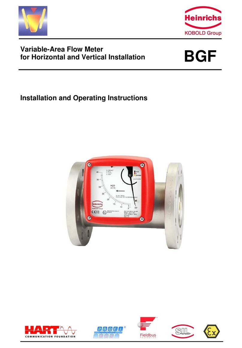
- Analog indicator approx. 90° with pointer
- Customized product scale
- ES transmitter with freely programmable user interface
- Parameters may be changed based on the ES
Operating Instructions.
11 Auxiliary power
see Electrical connection
12 CE mark
The measuring system meets the statutory requirements of
the following EU directives: Directive 94/9/EC (Equipment
and Protective Systems for Use in Potentially Explosive
Atmospheres), the Electromagnetic Compatibility (EMC)
Directive 89/336/EEC and the Pressure Equipment Directive
97/23/EC.
Heinrichs Messtechnik confirms compliance with the
directives by attaching the CE mark.
13 Order information
Please include the following information in your order:
product data, specific weight, temperature, pressure,
viscosity, material design, connection size, measuring range,
direction of flow, desired accessories, required approvals
and material certificates. See Device selection by model
code.
13.1 Available accessories
- Stainless steel indicator unit, glass window IP 66
- Indicator unit for high or low temperatures pulled
forward by 100 mm
- Fitting with heating or cooling jacket (with Ermeto or
flange connection)
- 1 or 2 inductive limit transducers
- KINAX or ES electric transmitter
- Drainable fitting (pump has been disconnected)
- Magnetic filter
- PROFIBUS PA
14 Standards and directives,
certificates and approvals
- Certified to DIN-EN 9001
- Production in accordance with AD guidelines and HPO
approval (TRB200/TRD201)
- TÜV approval for welding requirements in accordance
with DIN-EN 729-2
- Measuring range rated and converted to other products
according to VDE/VDI guidelines 3513
- Directive 94/9/Ec (Equipment and Protective Systems
for Use in Potentially Explosive Atmospheres)
- EN 50014:1997+A1-A2 - General requirements
- EN 50020:1994 - Intrinsic safety “i”
- Directive 89/336/EEC (EMC Directive)
- EN 61000-6-2:1999 – Immunity industrial environment
- EN 50 081-1 – Emitted interference residential
environment
- EN 55011:1998+A1:1999 – Group 1, Class B
- NAMUR recommendation NE 21
- EN 60529 – Degrees of protection through housing (IP
code)
- EN 61010 – Safety requirements for electrical
measuring, control and laboratory devices
- EN 60947-5-6:2000 – Switchgear and controlgear
- Directive 97/23/EC (Pressure Equipment Directive)
15 Safety instructions
15.1 Intended use
The BGF variable-area flowmeter may be used only for flow
measurements of fluid and gaseous media. The
manufacturer shall not be liable for damages that may result
from unintended or inappropriate use.
When dealing with an aggressive medium, clarify the
material durability of all wetted parts.
When using the device in hazardous areas, follow the
applicable national installation rules.
15.2 Installation, start-up and operating personnel
Only trained specialists authorized by the system operator
may carry out the installation, electrical installations, start-up,
maintenance and operation. They must read and
understand the operating manual and follow its instructions.
The required mounting, electrical installation, start-up and
maintenance work may only be carried out by expert and
authorized persons designated by the plant operator.
Basically, follow the conditions and provisions applicable in
your country.
16 Packaging, mounting and
shipment
Carefully unpack the device to avoid damaging it.
The operability of the measuring cell can be tested by
pressing the measuring body upwards in the direction of flow
using, for example, a wooden stick. The pointer position of
the indicator mechanism must follow the direction of
movement. The resetting spring resets the pointer back to
zero after the magnet carriers are released.
With the help of the delivery note enclosed in the packaging,
check whether all technically relevant data coincide with your
requirements.
Storage and installation must be done in a clean and dry
room so that contamination – especially of the interior of the
fitting – is avoided. Follow the limit values for ambient
temperature. When transporting the device to a remote
mounting location, we recommend that you reuse the
factory-issued packaging and the transport protection.
17 Maintenance
The device requires no maintenance if used according to its
intended purpose. However, if cleaning is necessary to
remove dirt from the measuring ring or the measuring body,
take note of the following aspects:
- Please take note that, with devices with built-in
electrical equipment, removing the indicator cover
restricts the EMC protection.
- Before removing a device, make sure that the pipeline
is free from the product, is pressureless and has cooled
down.
- Fittings with the insides coated may be carefully
cleaned after removal with a brush and the appropriate
cleansing agent. Carefully clean the measuring body
from possible coating. Attention: do not use the
measuring ring/cone and the measuring body with hard
objects (see Removing/installing the measuring body).
- The switching points of the limit transducers are
adjustable. To do this, remove the indicator cover,
unfasten the contact point indicator located on the scale
and readjust it. After the adjustment, reattach the bolts
Page 18 of 29


