Heinrichs BGN User manual

Variable-Area Flow Meter BGN
Installation and Operating Instructions
BGN 01/0621

Heinrichs Messtechnik
BGN Installation and Operating Instructions
Page 2 of 39 Subject to change without notice
Contents
1. INTRODUCTION...................................................................................................................... 4
2. IDENTIFICATION..................................................................................................................... 4
3 APPLICATIONS....................................................................................................................... 4
4 SAFETY INSTRUCTIONS....................................................................................................... 4
4.1 Intended use ........................................................................................................................... 4
4.2 Installation, start-up and operating personnel.................................................................... 4
5 PACKAGING, MOUNTING AND SHIPMENT......................................................................... 4
6 OPERATIONAL MODE AND SYSTEM DESIGN.................................................................... 5
6.1 Measuring principle ............................................................................................................... 5
6.2 System design........................................................................................................................ 5
7 INPUT....................................................................................................................................... 5
7.1 Measured variable.................................................................................................................. 5
7.2 Measuring range (lower-range and upper-range value)..................................................... 5
8 OUTPUT SIGNAL / ELECTRICAL EQUIPMENT / OPTIONS................................................ 7
8.1 Binary output.......................................................................................................................... 7
8.1.1 KEI 1 or KEI 2 limit switches .................................................................................................... 7
8.1.2 KEM 1 or KEM 2 limit transducers (special version)................................................................ 7
8.2 Analog output with the-electronic transmitter.................................................................... 7
8.3 Model ES-PPA and ES-FF..................................................................................................... 7
9 CHARACTERISTICAL VALUES............................................................................................. 7
9.1 Measuring accuracy............................................................................................................... 7
9.1.1 Reference conditions................................................................................................................ 7
9.1.2 Measuring accuracy................................................................................................................. 7
9.1.3 Repeatability............................................................................................................................. 7
9.1.4 Influence of ambient temperature ............................................................................................ 8
9.2 Influence of fluid temperature............................................................................................... 8
10 CONDITIONS OF USE ............................................................................................................ 8
10.1 Mounting requirements ......................................................................................................... 8
10.1.1 Mounting / start-up ................................................................................................................... 8
10.1.2 Device settings......................................................................................................................... 9
10.1.3 Adjusting the switch point for the inductive limit switch KEI.................................................... 9
10.1.4 Adjusting the switch point of SPDT Micro Switches KEM .................................................... 10
10.1.5 Installation in hazardous areas .............................................................................................. 10
10.2 Ambient conditions.............................................................................................................. 12
10.2.1 Ambient temperature ranges.................................................................................................. 12
10.2.2 Storage temperature .............................................................................................................. 12
10.2.3 Climatic category.................................................................................................................... 12
10.2.4 Degree of protection............................................................................................................... 12
10.2.5 Shock resistance/vibration resistance.................................................................................... 12
10.2.6 Electromagnetic compatibility................................................................................................. 12
10.2.7 Fluid temperature ranges....................................................................................................... 12
10.2.8 Diagrams: Max. ambient temperature dependent on fluid temperature for ES transmitter 12
10.2.9 Fluid pressure limit................................................................................................................. 13
10.2.10 Inlet and outlet sections .........................................................................................................13
10.2.11 Physical state......................................................................................................................... 13
10.2.12 Density ................................................................................................................................... 13
10.2.13 Viscosity................................................................................................................................. 13
10.2.14 Pressure (for gas measurement) ........................................................................................... 13
10.2.15 Pressure loss.......................................................................................................................... 13
11 CONSTRUCTION DETAILS.................................................................................................. 14
11.1 Type of construction/dimensions....................................................................................... 14
11.1.1 Aluminum indicator housing................................................................................................... 14
11.1.2 Dimensional drawing heating connection ............................................................................. 15
11.1.3 Indicator housing made of stainless steel..............................................................................16
11.2 Weights ................................................................................................................................. 17
11.3 Material.................................................................................................................................. 17
11.4 Process connection............................................................................................................. 17
11.5 Magnetic filter....................................................................................................................... 18
11.6 Electrical connection........................................................................................................... 18
11.6.1 Wiring diagram for ES transmitter (signal output 4-20 mA with HART).............................. 19
11.6.2 Wiring diagram for ES transmitter with 4-20 mA output and 2 limit switches ........................ 19

Heinrichs Messtechnik
BGN Installation and Operating Instructions
Page 3 of 39 Subject to change without notice
11.6.3 Wiring diagram for ES transmitter with 4- 20 mA output, pulse output and limit switches..... 20
11.6.4 Wiring diagram for inductive limit switches KEI .................................................................... 20
11.6.5 Wiring diagram for KEM 1 and KEM 2 micros witches ..........................................................21
11.6.6 Devices with unconnected cable end.....................................................................................21
12 INDICATOR UNIT.................................................................................................................. 21
13 POWER SUPPLY .................................................................................................................. 21
14 CE MARKING ........................................................................................................................ 21
15 ORDER INFORMATION........................................................................................................ 21
16 STANDARDS AND DIRECTIVES, CERTIFICATES AND APPROVALS ............................ 21
17 MAINTENANCE..................................................................................................................... 21
18 INSTALLING AND REMOVING CONE, FLOAT, DAMPING SETS/SPRING STOP ........... 22
19 TROUBLE SHOOTING.......................................................................................................... 22
20 RETURNING DEVICES FOR REPAIR AND SERVICE........................................................ 22
22 EXPLODED VIEWS............................................................................................................... 23
22.1 Fitting with measuring element .......................................................................................... 23
22.1.1 BGN-.... Standard version..................................................................................................... 23
22.1.2 BGN-.... with spring stop ....................................................................................................... 23
22.1.3 BGN-.... with damping piston ................................................................................................. 24
22.1.4 BGN-.... with damping piston and spring stop........................................................................ 24
22.1.5 BGN-.... small measuring ranges........................................................................................... 24
22.2 Indicator unit......................................................................................................................... 25
22.2.1 Complete indicator unit, with local scale...............................................................................25
22.2.2 Complete indicator unit, c/w 1 pc limit switch SJ 3,5-N........................................................ 25
22.2.3 Complete Indicator unit with 2 pcs limit switches SJ 3,5-N....................................................26
22.2.4 Complete indicator unit with 1 pc SPDT micro switch KEM................................................ 26
22.2.5 Complete indicator unit with 2 pcs SPDT micro switches KEM........................................... 26
22.2.6 Complete Indicator unit with transmitter ES Ex HART....................................................... 26
23 DECONTAMINATION CERTIFICATE FOR DEVICE CLEANING........................................ 30
24 EC TYPE EXAMINATION CERTIFICATE............................................................................. 31
25 DECLARATION OF CONFORMITY...................................................................................... 37

Heinrichs Messtechnik
BGN Installation and Operating Instructions
Page 4 of 39 Subject to change without notice
1. Introduction
These Installation and Operating Instructions serve as a tool for the correct installation, operation and maintenance of the device.
They are a supplement to the BGN Device Description. Read the manual carefully before the device is installed and put into use.
It does not include special versions or applications.
All devices are thoroughly checked for order compliance and operation before delivery. Upon receipt, please conduct a visual
inspection of possible damage that may be identified as having occurred during shipment. If you discover any defect, please
contact our head office in Cologne or the local sales office responsible for your area (KOBOLD Instruments USA contact info
below). Apart from a description of the error, we will need the equipment type and serial number of the delivery.
Heinrichs Messtechnik shall not furnish guarantee for any repair work done without prior notice. Unless otherwise agreed on, the
rejected parts must be made available to us in case a claim is made.
2. Identification
2.1. Supplier/manufacturer
KOBOLD Instruments Inc.
1801 Parkway View Drive
Pittsburgh PA 15205-1422
Tel.: 412-788-2830
Fax: 412-788-4890
E-Mail: [email protected]
Internet: http://koboldusa.com
2.2. Product type
Flow meter in all-metal design based on
the variable area principle
2.3. Issue date
19.10.2016
2.4. Version no
.
File: BGN_BA_16.02_en
3 Applications
The BGN meter is suitable for flow measurement of liquid or gaseous products in pipes. It shows the current flow rate in volume or
mass per unit in time. Please consider also the provisions for the use in hazardous areas.
Applications: flow measurement, dosing, monitoring, adjusting and control of liquid and gaseous products.
The meter’s design makes it ideal for processes under difficult and adverse operating conditions.
The devices are available with additional electrical equipment for process monitoring and control.
4 Safety instructions
4.1 Intended use
The BGN variable-area flow meter may be used only for flow measurements of fluid and gaseous media. The
manufacturer shall not be liable for damages that may result from unintended or inappropriate use.
When dealing with an aggressive medium, clarify the material resistance of all wetted parts.
When using the device in hazardous areas, follow the applicable national installation rules.
4.2 Installation, start-up and operating personnel
Only trained specialists authorized by the system operator may carry out the installation, electrical installations, start-
up, maintenance and operation. They must read and understand the operating manual and follow its instructions.
The required mounting, electrical installation, start-up and maintenance work may only be carried out by expert and
authorized persons designated by the plant operator.
Basically, follow the conditions and provisions applicable in your country.
5 Packaging, mounting and shipment
Carefully unpack the device to avoid damage. The float is secured against damage in transit depending on the device size.
Remove this transport protection from the fitting. By pressing the float from the bottom upwards (using a wooden stick, for
example), check whether the float can easily be moved upwards and slides back downwards. The pointer position of the indicator
unit must follow the direction of movement of the float.
With the help of the delivery note enclosed in the packaging, check whether all technically relevant data correspond with your
requirements.
Instruments series BGN will be
delivered without label stickers.
All important informations such as:
-Measuring range
-Manufacturer
-Serial number
-Model code
-CE marking
-Neccessary Ex marking
are printed on instrument scale and
can be read from there.

Heinrichs Messtechnik
BGN Installation and Operating Instructions
Page 5 of 39 Subject to change without notice
Storage and installation must be done in a clean and dry area so that contamination – especially of the interior of the fitting – is
avoided. Follow the limit values for ambient temperature. When transporting the device to a remote mounting location, we
recommend that you reuse the factory-issued packaging and the transport protection.
6 Operational mode and system design
6.1 Measuring principle
The measuring element consists of a sharp-edged measuring ring (1) and a conical float (2). A medium flows from the bottom to
the top through the measuring ring, lifting the float until the buoyancy force (A) and the weight of the float establish equilibrium.
As the height of the float varies, an annular clearance proportional to the flow appears between the float and the measuring ring.
The height of the float in the measuring ring is a measure of the flow. The permanent magnet (3) embedded in the float then
transmits this measure to the scale (5) and the optional electronic evaluators through a magnet tracking system (4).
6.2 System design
The meter consists of a cylindrical pipe with flange or NPT threaded connections on both sides. For measuring ranges from
5 to 50 l/h on, a measuring ring is inserted in the tube in which a conical float can move with vertical freedom. For small measuring
ranges of up to 4–40 l/h, the measuring cell consists of a conical measuring tube with cylindrical float.
The height of the float resulting from the flow rate is transmitted in a rotary motion by a built-in permanent magnet through a magnet
tracking indicator system in a rotation to the pointer axis of the analog indicator unit.
7 Input
7.1 Measured variable
Volume flow
7.2 Measuring range (lower-range and upper-range value)
The lower-range value is considered 10% of the upper-range value.
Measuring range span: 10-100%
1
Smallest measuring range: 0.5-5.0 l/h water
Largest measuring range: 13.000 - 130.000 l/h water (stainless steel)
1
for water like liquids
1
5
4
3
2
A

Heinrichs Messtechnik
BGN Installation and Operating Instructions
Page 6 of 39 Subject to change without notice
7.2.1. Measuring range chart
Reference conditions: acc. IEC 770
Water 20 °C; air 1,013 bar abs.
1) for BGN-P version (PTFE), float with tantalum collar, measuring cone made of borosilicate glass
measuring range: A 0.7–7.0 l/h, B 1.2–12 l/h, C 2.0–20 l/h
2) gas throttle in S version for gas measurement included in price (pressure loss 200 mbar)
3) not available in P version
4) sizing for higher viscosities not possible
5) only in S and H version, only with reduced sealing face
6) gas measurement not possible
7) with only atmospheric pressure a measurement is not possible. Indicated values are for orientation. For gas measurements
a factor of 2-3 of the inlet pressure should be considered
8) Restrictions for units with PTFE lining
:
Measuring range chart BGN
DN 1)8)
EN1092-1
ASME 8)
B16.5-2003
Flow Body
S… st.st.
P… PTFE
H… Hastelloy
Range
Code
Measuring ran
ge water
(1000 kg/m3; 1 mPas)
Measuring range air
(1.013 bar abs., 20°C) 7)
Pressure
loss
(mbar)
Note
15
½ " S10 A 0,5 – 5,0 I/h 0,015 - 0,15 m
3
/h 40
1) 2)
25
¾ ” S10 B 1 - 10 I/h 0,030 - 0,30 m
3
/h 40
1) 2)
1” S10 C 1,6 - 16 I/h 0,045 - 0,48 m
3
/h 40
1
) 2)
S10 D 2,5 - 25 I/h 0,075 - 0,75 m
3
/h 40
2)
S10 E 4 - 40 I/h 0,13 - 1,3 m
3
/h 40
2)
15
½ " S15 F 5 - 50 I/h 0,15 - 1,5 m
3
/h 40
20
¾ ” S15 G 7 - 70 I/h 0,2 - 2,1 m
3
/h 40
25
1” S15 H 10 - 100 I/h 0,3 - 3,0 m
3
/h 60
32
1 ¼” S15 I 16 - 160 I/h 0,5 - 4,6 m
3
/h 60
S15 J 25 - 250 I/h 0,7 - 7,0 m
3
/h 60
S15 K 40 - 400 I/h 1,0 - 11 m
3
/h 70
S15 L 60 - 600 I/h 1,7 - 17 m
3
/h 80
15
¾ ” S25 M 100 - 1000 I/h 3 - 30 m
3
/h 60
5)
20
1” S25 N 160 - 1600 I/h 4 - 46 m
3
/h 70
5)
25
S25 P 250 - 2500 I/h 7 - 70 m
3
/h 100
5)
32
S25 Q 400 - 4000 I/h 11-110 m
3
/h 100
5)
40
1 ½” S40 P 250 - 2500 I/h 7 - 70 m
3
/h 50
3)
S40 Q 400 - 4000 I/h 11 - 110 m
3
/h 120
3)
S40 R 600 - 6000 I/h 17 - 170 m
3
/h 180
3)
50
2” S50 Q 400 - 4000 I/h 11 - 110 m
3
/h 80
65
2 ½” S50 R 600 - 6000 I/h 17 - 170 m
3
/h 90
S50 S 1000 - 10000 I/h 29 - 290 m
3
/h 110
S50 T 1600 - 16000 I/h 46 - 460 m
3
/h 230
S50 U 2500 - 25000 I/h 70 - 700 m
3
/h 500
3) 4)
80
3” S80 T 1600 - 16000 I/h 46 - 460 m
3
/h 70
3 ½” S80 U 2500 - 25000 l/h 70 - 700 m
3
/h 100
S80 V 4000 - 40000 I/h 110 - 1100 m
3
/h 350
3)
100
4” S1H V 4000 - 40000 I/h 110 - 1100 m
3
/h 120
125
5” S1H W 6000 - 60000 I/h 170 - 1700 m
3
/h 360
S1H X 8000 - 80000 I/h 240 - 2400 m
3
/h 600
3) 4)
S1H 2 10000 - 100000 I/h -
3) 4) 6)
150
6” SH5 2 10000 - 100000 l/h -
3) 4) 6)
SH5 4 13000 - 130000 l/h -
3) 4) 6)

Heinrichs Messtechnik
BGN Installation and Operating Instructions
Page 7 of 39 Subject to change without notice
8 Output signal / electrical equipment / options
Inside the indicator housing different electrical
switches (max. 2) or transmitters may be mounted.
8.1 Binary output
By using the segment disks (double or single) to adjust the proximity switches or by using the switching lever for adjusting the
micro switches, any switching point between 10% and 90% of the flow rate can be set.
8.1.1 KEI 1 or KEI 2 limit switches
1 or 2 limit transducers,
Model SJ 3,5N, manufacturer Pepperl & Fuchs (special switches e.g. safety technology or 3-wire version possible)
Safety class: PTB Nr. 99 ATEX 2219 X
PTB Nr. 00 ATEX 2048 X
BGN flow meters can be equipped with max. 2 switches
8.1.2 KEM 1 or KEM 2 limit transducers (special version)
SPDT micro switches whose switching point is activated by a cam plate.
KEM 1 = 1 SPDT micro switch
KEM 2 = 2 SPDT micro switches
Maximum switching capacity:
230 VAC 50/60Hz 6 A
24 VDC 0.5 A
110 VDC 0.2 A
The switch points are usually factory pre-set. The procedure to the customer adjustments see section 10.1.4.
8.2 Analog output with the-electronic transmitter
The electrical transmitter ES is factory-calibrated to the delivered scale values. The signal output can only be supplied in
two-wire connection with 4-20 mA. The 4-20 mA signal includes HARTprotocol; alternatively it can have PROFIBUS PA. or
FIELDBUS FOUNDATION interface see Point 8.3
Additional options: 2 limit switches, alternatively 1 limit switch and 1 pulse output
The signal output and the limit switches can be configured using a HARTmodem operating on the following configuration
programs: PDM from Siemens or AMS from Rosemount. AHARThand-held terminal (with DD software) can also be used.
For more information about configuration, please refer to the separate Operating Instructions for the ES.
EX classification: DMT 00 ATEX 075 / II2G Ex ia IIC T6
When installing electrical equipment in hazardous areas, the conditions and provisions specified in the
approval documents must be followed. See section 10.1.5.
8.3 Model ES-PPA and ES-FF
The ES-PPA and ES-FF transmitters are FISCO field devices that are connected via a two-wire field bus circuit according to the
FISCO model.
The devices can also be connected to intrinsically safe fieldbus circuits which do not correspond to the FISCO model. In this case
the electrical maximum values (Ui, Ii, Pi, Li and Ci) must be observed.
Details for the use and operation can be found in separate instruction manual ES-PPA and ES-FF
9 Characteristical values
9.1 Measuring accuracy
9.1.1 Reference conditions
Water 20°C
9.1.2 Measuring accuracy
BGN-S/H : ±1,6% of actual qG=50% acc. VDI/VDE 3513-2 (for local indicator)
BGN-P: ±2,0% of actual qG=50% acc. VDI/VDE 3513-2 (for local indicator)
Additional inaccuracy for electronic transmitter ES = +/- 0.2%
9.1.3 Repeatability
±0.5 % of full scale

Heinrichs Messtechnik
BGN Installation and Operating Instructions
Page 8 of 39 Subject to change without notice
9.1.4 Influence of ambient temperature
1. Without electrical equipment and with limit transducer without influence
2. With transmitter ES ± 0.5 % / 10 K reference temperature 22°C
9.2 Influence of fluid temperature
Deviations in fluid temperature from the temperature observed during calibration can result in a proportional display fault because of
the corresponding change in density. Changes in viscosity cause a non-linear display fault.
10 Conditions of use
For the use in any process the VDI/VDE guidelines 3513, sheet 3, must be observed. The meter is suitable for :
1) Liquids with sufficient flow capabilities, which are free of solids, do not bond and do not tend to deposit.
2) Gases with linear / laminar flow behavior and an adequate inlet pressure.
10.1 Mounting requirements
The mounting location must be suitable for a vertical direction of flow from the bottom to the top.
Important: If that is impossible, then the flow meter series BGF may be used. The BGF can be used for both
horizontal and vertical flow directions.
The limit values for temperature and air humidity at the mounting location must be maintained. Avoid corrosive atmospheres. If this
cannot be avoided, ventilation must be installed.
Please ensure that there is adequate clearance from parts that might cause magnetic interferences such as
solenoid valves and ferromagnetic components like steel brackets/supports. We recommend the minimum
lateral distance between two adjacently mounted devices to be 300 mm. The devices can be mounted close
together if vertically offset by one device length. The minimum lateral clearance for interfering steel parts should be
200 mm. In case of doubt, check the interference by moving the device back and forth in the selected distance by
about 200 mm and evaluate whether the pointer position changes.
Select the mounting location so as to enable a reliable reading of the scale values. Please take note as well of the space
requirement for any possible disassembly of the device.
For process temperature < -40 °C and/or > +200 °C (392°F) the instruments must be equipped with a displaced indicator
(Assembled at Distance). Please consider the additional required space. ( see also point 11.1 )
Sample aluminum indicator displaced Sample st.st. indicator displaced
Inlet and outlet straight piping runs before and after the device are not necessary if the medium hasa linear flow profile.
Avoid mounting accessories at the inlet of the device.
If this is not possible maintain a minimum straight piping length of 250 mm at the inlet.
The nominal size of the pipes to be connected must correspond to that of the meter. Install valves behind the measuring equipment
for gas applications.
10.1.1 Mounting / start-up
The device must be mounted in accordance with the direction of flow from the bottom to the top (perpendicularly).
Please see the prior reference to the BGF it this is not possible.
The nominal size of the device and that of the pipes must be the same. The pressure rating and the dimensions of the flanges
must coincide. The surface roughness of the flange sealing surface must be suitable for the prescribed gaskets.
Please check whether possible accessories like spring stops, gas/liquid-type dampers are still correctly sitting on the flange. Check
whether the mounting clearance between the flanges of the pipes corresponds to the assembly dimension of the device plus two
gaskets. To achieve stress-free mounting, the flanges of the pipes must be aligned parallel to each other.
Use connecting bolts and gaskets in the prescribed dimensions. The gaskets must be suitable for the operating pressure, the
temperature and the measured medium. With PTFE-lined devices, use gaskets whose interior and exterior diameter correspond to
the sealing strip of the device.
Tighten the screws crosswise so that the process connections are tight. Refer to the screw torques, especially with PTFE-coated
devices.
The maximum torques for PTFE-coated devices are:
DN15/DN25 = 14 Nm/DN50 = 25 Nm/DN80 = 35 Nm/DN100 = 42 Nm (following VDI/VDE Guideline 3513).

Heinrichs Messtechnik
BGN Installation and Operating Instructions
Page 9 of 39 Subject to change without notice
Please check whether the pipe is adequately fixed and stable to prevent vibration or swinging of the device. (Do not use steel
mounting parts on the device.)
When used with gaseous media,installation position of e.g. adjusting valve (e.g. special option):If the device is calibrated to
more than 1.013 bars abs., the valve is usually installed at the flow meter outlet. At 1.013 bars abs. (free outlet) the valve is
installed at the flow meter inlet.
If there is risk of dirt or solid matter penetrating the process pipes, flush them beforehand so that those materials do not get
deposited in the device. Ferromagnetic solid matter such as weld spatter can lead to the breakdown of the device. If these
materials cannot be excluded during normal operating conditions, mount a magnetic filter (accessory) in front of the device. When
using liquids, flush to avoid a surge of gas bubbles. Slowly increase the supply pressure when using gases to prevent pressure
surges. Basically, avoid activation using solenoid valves to prevent the float from shooting upwards.
10.1.1.1
Liquid Measurement / start up
When measuring liquids process pipes must be accurately vented to avoid water hammers through gas contents. To
avoid float hammers the use of solenoid valves must be prevented.
10.1.1.2 Gas measurement / start up
When measuring gases, increase flow very slow to avoid float hammer inside the flow tube. At the same time, vary the
operating pressure through a setting valve so that the float will not be exposed by any flow hammer, this would damage
the float or measuring ring. Avoid fluid pulsation. On gas measurements flow meters with gas damping systems are
recommended.
10.1.2 Device settings
The measuring instrument is delivered ready for operation according to your order specifications. The limit switches are set to the
desired values. If you have submitted no requirements, the basic settings are:
1 switch: Minimum contact switching point at 10% of descending flow (damped/closed-circuit principle).
2 switches: Minimum contact switching point at 10% of descending flow and maximum contact switching point at
90% of ascending flow.
10.1.3 Adjusting the switch point for the inductive limit switch KEI
The inductive contact can be adjusted via a limit switch indicator (2) located at the front side of the scale
1) Remove 4 screws of the front cover and lift off the cover
2) !! do not remove the scale !!
3) Loosen 2 locking screws (3) of the red limit switch indicator (2)
4) Move the red switch indicator to the desired switch point on the scale
and tighten the locking screws (3)
5) Mount the cover and tighten the four screws
1 Pointer
2 Limit switch indicator (fig. MIN)
3 Limit switch indicator locking srews
4 Locking screws switching disc
5 Single switching disc KEI

Heinrichs Messtechnik
BGN Installation and Operating Instructions
Page 10 of 39 Subject to change without notice
10.1.4 Adjusting the switch point of SPDT Micro Switches KEM
KEM 1 and KEM 2 limit switches do not have limit switch indicators.
Switch point(s) are normally factory set.
To adjust the switch points use the following procedure:
1) Ensure that the supply lines are powerless and will not be switched
active during operation.
2) Remove 4 screws of the front cover and remove the cover.
3) !! do not remove the scale (4) !!
4) Move the pointer (3) carefully in direction of the desired switch point
5) Unfasten the screws (1) of the disc (2) carefully and move the disc towards the switching point of the micro switch
6) Depending on the switching function ( N/O or N/C ) the switch must be activated (for N/C ) or non activated (for N/O )
NOTE
Due to hysteresis of KEM switches they must not be used for ranges ≤250 l/h water
10.1.5 Installation in hazardous areas
10.1.5.1 Without electrical equipment
The basic version of the flow meter is a non-electrical device without its own ignition sources and meets DIN EN 13463-1
requirements. It can be used in hazardous areas that require Category 2 equipment.
Marking: II 2GD c
Reg. No.: BVS 03 ATEX H/B 112
Tech. File Ref. 03-02 X
Since the device does not have its own power sources that would result in a temperature increase, the fluid temperature is decisive
for the maximum surface temperature.
When used in potentially explosive dust atmospheres, the device must be cleaned regularly in order to avoid deposits
exceeding 5 mm.
10.1.5.2 With built-in limit switches
When the limit switches are installed, the device becomes an electrical assembly and gets a marking in accordance with
DIN EN 60079 of built-in electrical limit transducers.
The electrical and thermal data and the special conditions of the EC Type Examination Certificate of the built-in limit transducers
must be observed (see also the diagram in Section 10.2.1.
The influence of the fluid temperature on the built-in limit transducers must be observed. The over-temperature of the maximum
fluid temperature based on the maximum ambient temperature must be considered with a factor according to the following table:
Nominal size Factor for
standard
version
Factor for instruments
with the indicator on
disctance
DN15 and DN25 / 1/2" and 1" 0.2 0.07
DN40 and DN50 / 1,5" and 2" 0.25 0.085
DN80 and DN100 / 3" and 4" 0.3 0.1
DN150 / 6"
1 Locking screws switching disc
2 Switching disc
3 Pointer
4 Scale
5
Switching lever

Heinrichs Messtechnik
BGN Installation and Operating Instructions
Page 11 of 39 Subject to change without notice
Example for built-in limit switch at DN 15 (1/2") and DN 25 (1"):
Max. ambient temperature Tamb = 40°C
Max. fluid temperature Tm= 120°C
Factor for brought-in heat F = 0.2
Temperature class T4
Tü= Over-temperature
Ta= Ambient temperature of limit switch
CCCTambFTüTa
CCCTambTmTü °=°+°=+=
°
=
°
−
°
=
−
=
56402,0*80*
8040120
In accordance with the tables in the PTB 99 ATEX 2219 X EC Type Examination Certificate, the SJ 3,5-... N... inductive sensor must
be operated in the T5 temperature class with an intrinsically safe circuit that does not exceed the maximum values of the Type 3
circuit.
When using the device in hazardous areas, follow the applicable national installation rules.
Example for calculating the max. fluid temperature based on the max. ambient temperature for the built-in sensor Type ES
for DN 15/25.
Ta= 70°C
Tamb = 60°C
F= 0.2
CC
CC
Tamb
F
TambTa
Tm °=°+
°−°
=+
−
=11060
2,0 6070
10.1.5.2.1 Marking for the device with built in SJ 3,5...N... limit switch
PTB 99 ATEX 2219 X
II 2G EEx ia IIC T6
ZELM 03 ATEX 0128 X
II 1D Ex iaD 20 T108°C
10.1.5.2.2 Marking for the device with built in electric transmitter ES
DMT 00 ATEX 075
II2G Ex ia IIC T6
10.1.5.3 Atmospheric conditions
In accordance with EN 1127, a “potentially explosive atmosphere“ is defined as a mixture of air and combustible gases, vapor, mist
or dust under atmospheric conditions. Such conditions are defined in EN 13463-1, para. 1, with values Tatm = -20 °C to +60 °C and
Patm = 0.8 to 1.1 bar. Outside this range, safety parameters for most ignition sources are not available.
Usually, variable-area flow meters operate under operating conditions outside the atmospheric conditions of 0.8 to 1.1 bar.
Irrespective of the zone classification –safety parameters of explosion protection – are basically not applicable to the inside of the
measuring tube.
10.1.5.4
Therefore operation with combustible products is only allowed if a potentially explosive air mixture is not
formed inside the flow meter. Where this condition is not met, the operator will need to assess the ignition hazard in
each individual case and give due consideration to existing parameters (e.g. pressure, temperature, process product,
materials of construction for the measuring tube).
Ground connection
In variable-area flow meters, in principal it is possible that through the flow of non-conductive liquids a charge separation can
occur inside the measuring tube. A dissipation of such charge carriers from the metal flow tube through earthing must be ensured
by permanent earthing via process connections through the operator.
If grounding cannot be made via the process connections (plastic process connections or undefined connections), the flow meter
must be connected to the local ground potential via the flanges. This connection only ensures electrostatic grounding of the device
and does not meet the requirements for equipotential bonding.

Heinrichs Messtechnik
BGN Installation and Operating Instructions
Page 12 of 39 Subject to change without notice
10.2 Ambient conditions
10.2.1 Ambient temperature ranges
Without electrical accessories:
-40°C to +80°C
With limit switches:
-40 °C to +65°C
With ES signal output:
-40°C to +70°C
For the hazardous area version, take note of the maximum ambient temperatures depending on the temperature class as specified
on the Type Examination Certificate.
10.2.2 Storage temperature
The storage temperatures are identical to the ambient temperature ranges.
10.2.3 Climatic category
Weather-protected and/or unheated locations, class C according to IEC 654 Part 1
10.2.4 Degree of protection
IP 65 (Aluminum indicator unit)
IP 67 (Stainless steel indicator unit)
10.2.5 Shock resistance/vibration resistance
The meter should be protected from extreme shocks and vibrations, which could cause damage.
10.2.6 Electromagnetic compatibility
EN 61000-6-2:2011 Störfestigkeit Industriebereich / immunity industrial environment
EN 61000-6-3:2011 Störaussendung Wohnbereich / emission residential, commercial
EN 55011:2011 Gruppe 1, Klasse B , Funkstörungen / Group 1 Class B , ISM ratio-frequency equipment
EN61326-1:2013 EMV-Anforderungen / EMC requirements
NAMUR recommendation NE 21Fluid conditions
10.2.7 Fluid temperature ranges
BGN-S/H : - 40°C to +200°C Special versions: -80°C to +350°C
BGN-P : - 20°C to +125°C
10.2.8 Diagrams: Max. ambient temperature dependent on fluid temperature for
ES transmitter

Heinrichs Messtechnik
BGN Installation and Operating Instructions
Page 13 of 39 Subject to change without notice
10.2.9 Fluid pressure limit
Standard design BGN-S/H – DN 15/25/40/50/80 PN 40;
DN 100 PN 16
Special design – up to PN 400
BGN-P – DN 15/25/50/80/100 PN 16
10.2.10 Inlet and outlet sections
Inlet and outlet straight piping runs are not required on a linear flow profile of the fluid. For an extremely non-linear flow profile
(e.g. shut-off/control valves are located at the meter inlet), we recommend an inlet section with a mounting length of 250 mm
(see also guidelines in accordance with VDI/VDE 3513).
10.2.11 Physical state
Liquid or gaseous
10.2.12 Density
Liquids: up to 2.0 kg/l
Gases: no restrictions
10.2.13 Viscosity
The influence of viscosity depends on various factors. Therefore, it must be calculated for each application.
10.2.14 Pressure (for gas measurement)
The measured values only apply to the calibrated media data stated on the scale. Any change or deviation in pressure will
cause a display fault.
10.2.15 Pressure loss
Depends on the meter size and the measuring range (see measuring range table page 6).
Heinrichs Messtechnik
BGN Installation and Operating Instructions
Page 14 of 39 Subject to change without notice
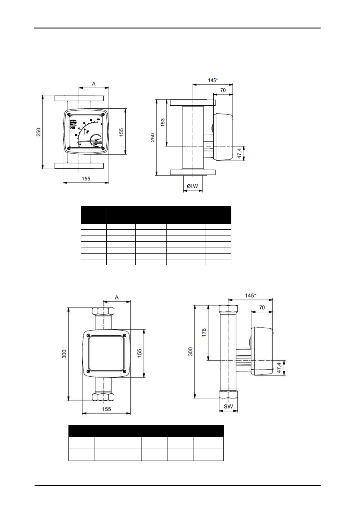
11 Construction details
11.1 Type of construction/dimensions
11.1.1 Aluminum indicator housing
11.1.1.1 Version with flange connection
Dimensions
11.1.1.2 Version with threaded connection
Dimensions
Pipe
Size
DN /
ANSI
PN
/
CL
Ø l.W
(mm)
A
(mm)
S15 15 / 1/2" 40 / 300 26 77,0
S25 25 / 1" 40 / 300 32 80,1
S40 40 / 11/2" 40 / 300 46 87,9
S50 50 / 2" 40 / 300 70 100,9
S80 80 / 3" 40 / 300 102 117,4
S1H 100 / 4" 16 / 300 125 130,1
SH5 150 / 6" 16 / 150 158 149,6
Pipe
NPT(f) / G(f)
(in)
PN
/
CL
SW
A
(mm)
S15 1/4-3/8-1/2-3/4 40 / 300 36 77,0
S25 1/4-3/8-1/2-3/4 40 / 300 36 80,1
S40 3/4-1-1 1/4 40 / 300 60 87,9
S50 1 1/4-1 1/2-2 40 / 300 80 100,9
*=+100 mm for displaced indicator
*=+100 mm for displaced indicator

Heinrichs Messtechnik
BGN Installation and Operating Instructions
Page 15 of 39 Subject to change without notice
11.1.2 Dimensional drawing heating connection
Dimensions
11.1.2.1 Connections for heating jacket
Pipe for Ermeto 12 mm
Flange in acc. with DIN / EN DN 15 (1/2") or DN 25
1)
(1") PN 40
Flange in acc. with ASME ½“ 150 lbs
1) DN 25 flange is a special version
DN / ANSI
PN
/ Cl
B
(Flange)
(mm)
B
(Ermeto)
(mm)
S
(mm)
X
(mm)
15 / 1/2" 40 / (150/300) 110 53 150 3,0
25 / 1" 40 / (150/300) 110 58,5 150 4,9
40 / 11/2" 40 / (150/300) 130 63 150 2,65
50 2" 40 / (150/300) 140 77,5 150 3,5
80 / 3" 16 / (150/300) 160 93,5 150 4,5
100 / 4" 16 / (150/300) 175 110 120 0
*=+100 mm for displaced indicator

Heinrichs Messtechnik
BGN Installation and Operating Instructions
Page 16 of 39 Subject to change without notice
11.1.3 Indicator housing made of stainless steel
11.1.3.1 Version with flange connection
Dimensions
11.1.3.2 Version with threaded connection
Dimensions
Pipe
Size
DN /ANSI
PN
/
CL
Ø
l. W
.
(mm)
A
(mm)
S15 15 / 1/2" 40 / 300 26 99,5
S25 25 / 1" 40 / 300 32 102,6
S40 40 / 11/2" 40 / 300 46 110,4
S50 50 / 2" 40 / 300 70 123,4
S80 80 / 3" 40 / 300 102 139,7
S1H 100 / 4" 16 / 300 125 152,4
SH5 150 / 6" 16 / 150 158 170,2
Pipe
NPT(f) / G(f)
(in)
PN
/CL
SW
A
(mm)
S15 1/4-3/8-1/2-3/4 40 / 300 36 99,5
S25 1/4-3/8-1/2-3/4 40 / 300 36 102,6
S40 3/4-1-1 1/4 40 / 300 60 110,4
S50 1 1/4-1 1/2-2 40 / 300 80 123,4
*=+100 mm for displaced indicator
*
=+100 mm for displaced indicator

Heinrichs Messtechnik
BGN Installation and Operating Instructions
Page 17 of 39 Subject to change without notice
11.2 Weights
Fitting
Nominal Size
Weight
(kg)
with
Aluminum Indicator
Weight
(kg)
with
St.st. indicator
S15 DN 15 3,3 4,0
S25 DN 25 4,2 4,9
S40 DN 40 6,5 7,2
S50 DN 50 8,7 9,4
S80 DN 80 13,8 14,5
S1H DN 100 14,5 15,2
SH5 DN 150 32,0 32,4
Fitting
Nominal Size
Weight
(kg)
with
Aluminum Indicator
Weight
(kg)
with
St.st. indicator
S15 ¾“, 150 lbs, ASME B16.5 3,1 3,8
S25 1“, 150 lbs, ASME B16.5 3,8 4,5
S40 1 ½“, 150 lbs, ASME B16.5 5,2 5,8
S50 2“, 150 lbs, ASME B16.5 7,4 8,1
S80 3“, 150 lbs, ASME B16.5 13,0 13,7
S1H 4“, 150 lbs, ASME B16.5 17,2 17,9
SH5 6“, 150 lbs, ASME B16.5 33,5 34,0
Fitting
Nominal Size
Weight
(kg)
with
Aluminum Indicator
Weight
(kg)
with
St.st. indicator
S15 ¾“, 300 lbs, ASME B16.5 4,0 4,6
S25 1“, 300 lbs, ASME B16.5 4,9 5,6
S40 1 ½“, 300 lbs, ASME B16.5 7,4 8,1
S50 2“, 300 lbs, ASME B16.5 8,9 9,6
S80 3“, 300 lbs, ASME B16.5 16,2 16,9
S1H 4“, 300 lbs, ASME B16.5 24,6 25,3
SH5 6“, 300 lbs, ASME B16.5 49,7 50,2
Fitting
Thread
NPT(f) / G(f)
(in)
Weight
(kg)
with
Aluminum Indicator
Weight
(kg)
with
St.st. indicator
S15 1/4-3/8-1/2-3/4 2,3 3,0
S25 1/4-3/8-1/2-3/4 2,4 3,1
S40 3/4-1-1 1/4 3,4 4,1
S50 1 1/4-1 1/2-2 5,3 6,0
11.3 Material
Fitting
Type
Measuring tube
Lining of
measuring tube
Flanges
Flange lining
Float
BGN – S Stainless steel none Stainless steel none Stainless steel
BGN – P (Qmax. 5/10/16 l/h H
2
O) Stainless steel PTFE / glass Stainless steel PTFE PTFE / Tantalum
BGN – P Stainless steel PTFE Stainless steel PTFE PTFE
BGN – H DN15/25 ¾“/1“ Hastelloy HC4 none Hastelloy HC4 none Hastelloy HC4
BGN – H > DN40 / 1½” Hastelloy HC4 none Stainless steel Hastelloy HC4 Hastelloy HC4
Indicator units
Type
Base plate
Housing
BGN – S/P/H Aluminium Aluminium, safety glass window
Optional Stainless steel Stainless steel, safety glass window
11.4 Process connection
DIN
BGN
-
S/H
BGN
-
P
DN 15 PN 40 PN 16
DN 25 PN 40 PN 16
DN 40 PN 40 PN 16
DN 50 PN 40 PN 16
DN 80 PN 40 PN 16
DN 100 PN 16 PN 16
DN 150 PN16 --

Heinrichs Messtechnik
BGN Installation and Operating Instructions
Page 18 of 39 Subject to change without notice
A
SME
BGN S/ H
BGN P
ANSI ¾“ B16.5 150 lbs
1)
300 lbs
1)
150 lbs
2)
300 lbs
2)
ANSI 1“ B16.5 150 lbs
1)
300 lbs
1)
150 lbs
2)
300 lbs
2)
ANSI 1 ½“ B16.5 150 lbs
1)
300 lbs
1)
150 lbs
2)
300 lbs
2)
ANSI 2“ B16.5 150 lbs
1)
300 lbs
1)
150 lbs
2
)
300 lbs
2)
ANSI 3“ B16.5 150 lbs
1)
300 lbs
1)
150 lbs
2)
300 lbs
2)
ANSI 4“ B16.5 150 lbs
2)
300 lbs
2)
150 lbs
2)
300 lbs
2)
ANSI 4“ B16.5 150 lbs
1)
Entire device PN 40
2)
Entire device PN 16
Additional equipment:
special flanges (e.g. JIS), threaded connections, food connection (e.g. TriClamp), welding connection
The S/H versions in special design are available for higher pressure on request.
11.5 Magnetic filter
The BGN flow meter is sensitive to impure media. Before installing the device, clean the pipes of dirt, spatter and other foreign
matter. If the mediacontains solid particles, connect a suitable filter in series. When dealing with flow media with ferrous particles, we
recommend using a magnetic filter.
To protect both magnetic filter types, MF-S (stainless steel) and MF-P/S (PTFE/stainless steel),
from corrosion, encapsulated permanent magnets are laid out in spiral form. The spiral
mounting produces optimum effect at small pressure loss.
The filter can be supplied with groove or tongue, projection or return, other
standards or special connections according to customer demand.
Dimensions:
11.6 Electrical connection
Wiring
To connect the power supply, remove the indicator cover, insert the connector cable into the cable gland and attach it to the terminals
according to the terminal diagram. Tighten the cable gland securely, remount the indicator cover and close it tightly.
Please observe the following wiring instruction carefully.( Improper wiring will cause loss of guarantee)
•Cable glands are not part of the delivery
•The cable gland must fit the indicator housing thread
•The cable gland must fit the diameter of the cable
•The cable must form a pig tail (drip leg) in front of the gland to avoid
water ingress - see sketch on the right
•Cable glands must not point upward
•The delivered cable gland connection sealing screw - delivered with
instruments with no signal transmitter - must be removed
•The sealing of the cable glands must correspond with the instructions
of the original cable gland manufacturer. Wrongly or incorrect tightened
cable glands will cause water ingress into the indicator housing
DN
/ inch
g (mm)
15 / 1/2" 45
25 / 1" 68
40 / 11/2" 88
50 / 2" 102
65 / 21/2" 122
80 / 3" 138
100 / 4" 158

Heinrichs Messtechnik
BGN Installation and Operating Instructions
Page 19 of 39 Subject to change without notice
11.6.1 Wiring diagram for ES transmitter (signal output 4-20 mA with HART)
11.6.2 Wiring diagram for ES transmitter with 4-20 mA output and 2 limit switches

Heinrichs Messtechnik
BGN Installation and Operating Instructions
Page 20 of 39 Subject to change without notice
11.6.3 Wiring diagram for ES transmitter with 4- 20 mA output, pulse output and limit switches
11.6.4 Wiring diagram for inductive limit switches KEI
Table of contents
Other Heinrichs Measuring Instrument manuals


