G.R.A.S. Sound & Vibration
Single-channel Low-noise Measuring System consisting of: Type 40HF and Type 12HF - Page 4
1. Introduction and Description
Fig. 1.1 shows a 1-inch Low-noise Level Microphone System Type 40HF which comprises:
• 1-inchMicrophoneType40EH.
• 1-inchPreamplierType26HFwithtwobuilt-incompensationltersandanoverload-warn-
ing LED.
To complete the system, a special single or 10-channel power module is required and is avail-
able from G.R.A.S., i.e.
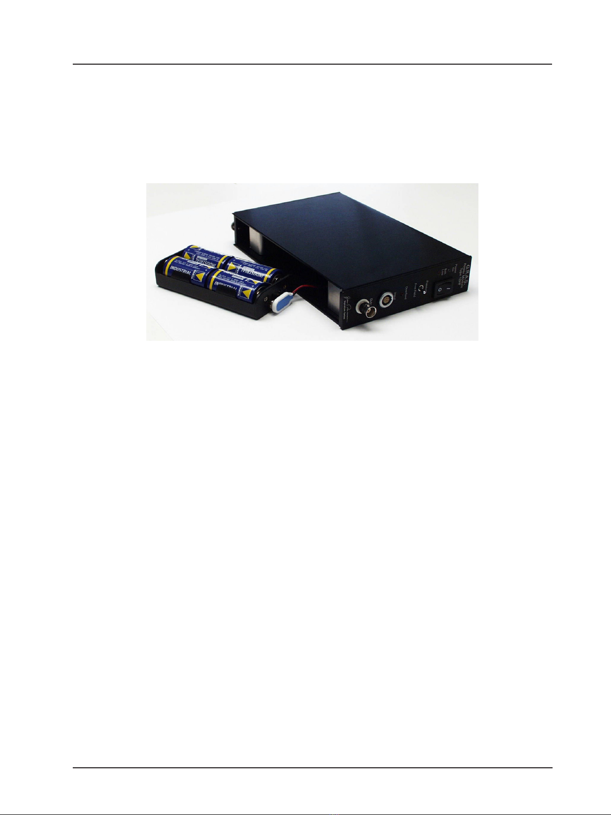
• Type12HFforsingle-channelmeasurements,seeFig.1.2(left).
Or
• Type12HMformulti-channel(1to10)measurements,seeFig.1.2(right)
Thechosenpowermoduleprovidesallnecessaryvoltagesforpoweringthepreamplier(s)as
well as polarising the microphone(s).
Fig. 1.3 shows a Single-channel Low-noise Measuring system (as described in this document)
and consists of:
• 1-inchLow-noiseLevelMicrophoneSystemType40HF.
• PowerModuleType12HF.
Note: the power module must be ordered separately and the tripod and tripod adapter are
optional extras.
1.1 Microphone Type 40EH
The Type 40EH is a special high-sensitive 1-inch pressure microphone with a nominal sensitivity
of110mV/Pa.Itisexternallypolarisedwithaspeciallyreducedinherentnoiseoorinorderto
achieve a high dynamic range and wide frequency range.
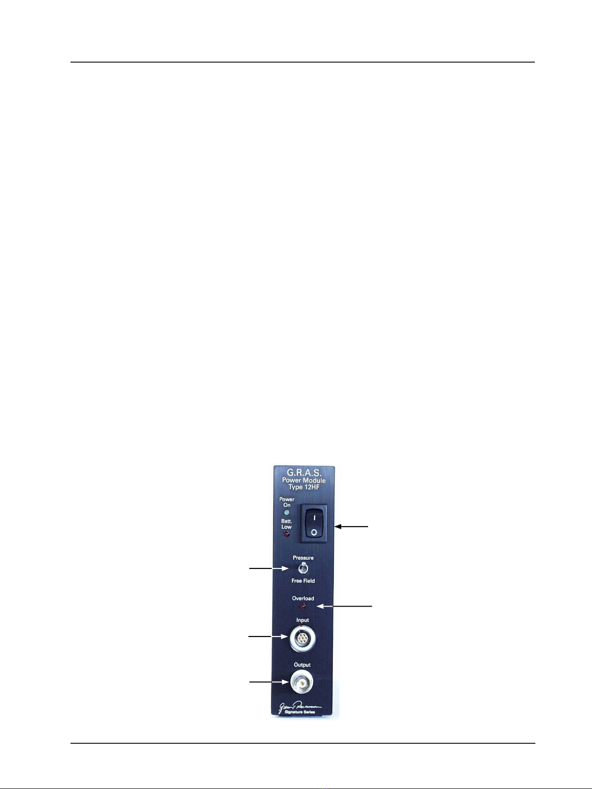
1.2 PreamplierType26HF
Thebodyofthepreamplierhasanoverload-warningLED,(Fig.1.1),whichisrepeatedonthe
front panel of the chosen power module (Fig. 2.1).
Thesignalofthemicrophoneisampliedby20dBinthePreamplierType26HF.
Thetwocompensationltersgivethesystemtwoparalleloutputswhichcorrespondto:
a) linear pressure-frequency response.
b) linearfree-eldfrequencyresponseatanangleof0°incidence.
The choice of which frequency response to use is made via a two-position switch marked Pres-
sure / Free Field: on the front panel of the power module (see Fig. 2.1).
Fig.1.4showstheresponsesofthetwocompensationltersaswellasthefree-eldresponse
for0°incidence.Note:free-eldcorrectionsareaddedtothelowestcurve.
Fig.1.5showsthewhatthesefree-eldcorrectionsareforvariousanglesofincidence.
Fig.1.6shows,foracompletelow-noisemeasuringsystem,atypicalnoiseoorin⅓-octave
bands for both the linear and A-weighted cases.
Fig. 1.1 1-inch Low-noise Measurement Microphone System Type 40HF
Overload-warning LED indicates when the measured
sound pressure level overloads the system’s electronics