Heinrichs TMU User manual
Heinrichs Messtechnik GmbH
OPERATING MANUAL TMU / UMC3
May 2021
Coriolis Mass Flow Meter
TMU
2nd Generation
Installation and operation manual with UMC3
Please read the instructions carefully and store them in a safe place

Heinrichs Messtechnik GmbH
Page 2 of 122
OPERATING MANUAL TMU / UMC3
Contents
INTRODUCTION................................................................................................................................5
I. Shipping and storage; product inspection................................................................................................ 5
II. Warranty ................................................................................................................................................. 5
III. Maintenance, Repair and Hazardous substances..................................................................................... 5
IV. Disposal ................................................................................................................................................... 5
V. Supplementary operating instructions..................................................................................................... 5
VI. Operating manual of explosion-proof flowmeters................................................................................... 5
1. IDENTIFICATION......................................................................................................................5
2. STEPS PRIOR TO OPERATION...................................................................................................7
2.1 Safety advisory for the user ..................................................................................................................... 8
2.2 Hazard warnings ...................................................................................................................................... 8
2.3 Proper use of the device .......................................................................................................................... 9
2.4 Installation and servicing......................................................................................................................... 9
2.5 Returning your flowmeter for servicing or calibration ............................................................................10
2.6 Replacement of the transmitter electronics............................................................................................10
2.7 Maintenance...........................................................................................................................................11
Transmitter.............................................................................................................................................. 11
Coriolis mass flow sensor ........................................................................................................................11
3. THE TMU SENSOR .................................................................................................................12
3.1 Application domain of the TMU sensor...................................................................................................12
3.2 Mode of operation..................................................................................................................................12
Measuring principle ................................................................................................................................12
System configuration ..............................................................................................................................12
Acquisition............................................................................................................................................... 12
3.3 Performance characteristics of the TMU sensor......................................................................................13
Reference conditions .............................................................................................................................. 13
TMU flow ranges .....................................................................................................................................13
Density measurement.............................................................................................................................14
Accuracy ..................................................................................................................................................15
Pressure loss TMU...................................................................................................................................16
Environmental Conditions....................................................................................................................... 17
3.4 Operating conditions ..............................................................................................................................18
Installation...............................................................................................................................................18
Installation Orientation ...........................................................................................................................19
Pressure surges .......................................................................................................................................21
Using the device with hazardous fluids...................................................................................................21
Vibration stability .................................................................................................................................... 22
Process conditions................................................................................................................................... 22
Gas content .............................................................................................................................................22
Process pressure range ...........................................................................................................................23
Outlet pressure .......................................................................................................................................23
Connection to the transmitter ................................................................................................................23
3.5 Construction details................................................................................................................................24
Dimensions and weight...........................................................................................................................24
Dimensions of the sensor types TMU 006 to TMU 050 ..........................................................................26
Dimensions of the sensor types TMU 080 to TMU 300 ..........................................................................28
Dimension drawings for sensors with heating ........................................................................................31
Material...................................................................................................................................................32

Heinrichs Messtechnik GmbH
OPERATING MANUAL TMU / UMC3
Page 3 of 122
4. UMC3 TRANSMITTER ............................................................................................................33
4.1 Application domain of the UMC3 transmitter.........................................................................................33
4.2 Mode of Operation.................................................................................................................................33
4.3 System configuration..............................................................................................................................33
4.4 UMC3 performance characteristics.........................................................................................................33
4.5 Operating conditions ..............................................................................................................................34
Installation conditions and cable glands ................................................................................................. 34
NPT cable glands ..................................................................................................................................... 34
Environmental conditions .......................................................................................................................35
Process conditions................................................................................................................................... 36
4.6 DSB data memory module......................................................................................................................36
4.7 Input measured variables .......................................................................................................................37
Measured Values.....................................................................................................................................37
Measuring range .....................................................................................................................................38
4.8 Outputs ..................................................................................................................................................38
Output circuits......................................................................................................................................... 38
Current outputs.......................................................................................................................................39
4.9 Construction details UMC3 .....................................................................................................................41
Mounting / Dimensions...........................................................................................................................41
Weight.....................................................................................................................................................42
Material...................................................................................................................................................42
5. ELECTRICAL CONNECTIONS UMC3........................................................................................43
5.1 Mains connections and their protection classes......................................................................................43
Wiring diagrams ......................................................................................................................................43
The output terminals............................................................................................................................... 44
Sensor connection...................................................................................................................................46
6. CERTIFICATES AND APPROVALS ............................................................................................49
6.1 Conformity to CE Directives ....................................................................................................................49
6.2 Explosion protection...............................................................................................................................49
6.3 Custody transfer applications .................................................................................................................49
6.4 Patents ...................................................................................................................................................49
7. OPERATION...........................................................................................................................50
7.1 Control unit BE4......................................................................................................................................50
Introduction ............................................................................................................................................50
Operating modes.....................................................................................................................................51
Operator interface ..................................................................................................................................51
The keys and their functions ................................................................................................................... 52
Functional classes, functions and parameters ........................................................................................53

Heinrichs Messtechnik GmbH
Page 4 of 122
OPERATING MANUAL TMU / UMC3
7.2 UMC3 transmitter functional classes ......................................................................................................55
MEASURED VALUES functional class.......................................................................................................56
PASSWORD functional class .................................................................................................................... 61
COUNTER functional class.......................................................................................................................63
MEASUREMENT PROCESSING functional class........................................................................................ 65
FLOW functional class .............................................................................................................................68
DENSITY functional class ......................................................................................................................... 73
TEMPERATURE functional class...............................................................................................................80
PULSE OUTPUT functional class ..............................................................................................................83
STATUS functional class...........................................................................................................................86
CURRENT OUTPUTS functional class ....................................................................................................... 90
SIMULATION functional class .................................................................................................................. 95
SELF-TEST functional class.......................................................................................................................99
UMC3 TRANSMITTER SETTINGS functional class ..................................................................................102
SENSOR SETTINGS functional class........................................................................................................107
7.3 Density calibration................................................................................................................................110
Conditions .............................................................................................................................................110
Procedure..............................................................................................................................................110
8. TROUBLE SHOOTING...........................................................................................................112
8.1 Self-help Checklist.................................................................................................................................112
8.2 UMC3 transmitter error messages........................................................................................................113
Standard operating mode .....................................................................................................................113
Custody transfer mode..........................................................................................................................113
List of error messages ...........................................................................................................................113
8.3 Returning the Meter.............................................................................................................................117
Declaration of Decontamination...........................................................................................................118
9. DECLARATION OF CONFORMITY .........................................................................................119

Heinrichs Messtechnik GmbH
OPERATING MANUAL TMU / UMC3
Page 5 of 122
Introduction
I. Shipping and storage; product inspection
Shipping and storage
The device is to be safeguarded against dampness, contamination (especially the inside of the flow meter),
impact and damage. Open the packaging with caution to prevent unintentional damage.
Adhere to the temperature limits during storage.
Product inspection
Upon receipt of the product, check the contents of the box and the product particulars against the
information on the delivery slip and order form so as to ensure that all ordered components have been
supplied. Notify us of any shipping damage immediately upon receipt of the product. Any damage claim
received at a later time will not be honoured.
II. Warranty
Your flowmeter was manufactured in accordance with the highest quality standards and was thoroughly
tested prior to shipment. However, in the event any problem arises with your device, we will be happy to
resolve the problem for you as quickly as possible under the terms of the warranty, which can be found in
the terms and conditions of delivery. Your warranty will only be honoured if the device was installed and
operated in accordance with the instructions for your device. Any mounting, commissioning and/or
maintenance work is to be carried out by qualified and authorized technicians only.
III. Maintenance, Repair and Hazardous substances
When used in the intended manner no special maintenance is required. However, the flowmeter should be
checked within the context of routine maintenance of the facility and the pipelines. Should a repair,
calibration or maintenance become necessary, be sure to clean the device thoroughly and follow the steps in
section 8.3, “Returning the Meter” before returning the device to Heinrichs Messtechnik.
The operator is liable for any substance removal or personal damage costs arising from inadequate cleaning
of a device sent for repair.
IV. Disposal
Observe the regulations applicable to disposal in the country of installation!
V. Supplementary operating instructions
Supplement operating manuals are available for special features, interfaces and operations relating to your
device, request your copy from our service department.
VI. Operating manual of explosion-proof flowmeters
For installation of the flowmeter within hazardous areas read the operation manual of explosion-proof
flowmeters. It contains all the EX-relevant information for your flowmeter.
Warning!
Only devices designated as EX-certified on their rating plates may be used in areas of
potentially explosive atmospheres!
The use of standard equipment in EX-hazardous areas is strictly prohibited.

Heinrichs Messtechnik GmbH
Page 6 of 122
OPERATING MANUAL TMU / UMC3
1. Identification
Manufacturer:
Heinrichs Messtechnik GmbH
Robert-Perthel-Strasse 9
D-50739 Cologne
Germany
Product type:
Mass flow-rate meter for liquid and gaseous products
Product name:
Sensor type: TMU 2nd Generation
Transmitter type: UMC3
File name:
tmu_umc3_ba_21.02_en.docx
Version:.
21.02, dated, 19 May 2021

Heinrichs Messtechnik GmbH
OPERATING MANUAL TMU / UMC3
Page 7 of 122
2. Steps prior to operation
It is essential that you read these operating instructions before installing and
operating the device. The device is to be installed and serviced by a qualified
technician only. The UMC transmitter is to be used exclusively to measure mass
and volume flow, as well as liquid and gas density and temperature, in conjunction
with a Heinrichs Messtechnik TM, TME, TMR, TMU, TM-SH or HPC sensor.
Downloading of the present document from our web site www.heinrichs.eu and printing out this
document is allowed only for the purposes of using our mass flowmeters. All rights reserved. No
instructions, wiring diagrams, and/or supplied software, or any portion thereof, may be produced, stored,
in a retrieval system or transmitted by any means, electronic, mechanical, photocopying or otherwise,
without the prior written permission of Heinrichs Messtechnik GmbH.
Although the materials in the present document were prepared with extreme care, errors cannot be
ruled out. Hence, neither the company, the programmer nor the author can be held legally or otherwise
responsible for any erroneous information and/or any loss or damage arising from the use of the
information enclosed.
Heinrichs Messtechnik GmbH extends no express or implied warranty concerning the applicability of the
present document for any purpose other than that described.
We plan to optimize and improve the products described and in so doing will incorporate not only our
own ideas but also, and in particular, any suggestions for improvement made by our customers. If you
feel that there is any way in which our products could be improved, please send your suggestions to the
following address:
Company:
Heinrichs Messtechnik GmbH
HM-EE (R&D Department)
Robert-Perthel-Strasse 9
D-50739 Cologne
Germany
or:
via fax : +49 (221) 49708-178
Note:
We reserve the right to change the technical data in this manual in the light of any
technical progress that might be made.
For updates regarding this product, visit our website at www.heinrichs.eu, where you
will also find contact information for the Heinrichs Messtechnik distributor nearest you.
For information regarding our own sales operations, contact us at info@heinrichs.eu.

Heinrichs Messtechnik GmbH
Page 8 of 122
OPERATING MANUAL TMU / UMC3
Safety advisory for the user
The present document contains the information that you need in order to operate the product described
herein properly. This document is intended for use by qualified personnel. This means personnel who are
qualified to operate the device described herein safely, including:
electronics engineers,
electrical engineers, or
service technicians
who are conversant with the safety regulations pertaining to the use of electrical and automated
technical devices and with the applicable laws and regulations in their own country.
Such personnel must be authorized by the facility operator to install, commission and service the product
described herein, and must have read and understood the contents of this operating instructions before
working with the device.
Hazard warnings
The purpose of the hazard warnings listed below is to ensure that device operators and maintenance
personnel are not injured and that the flow meter and any devices connected to it are not damaged.
The safety advisories and hazard warnings in the present document that aim to avoid placing operators
and maintenance personnel at risk and to avoid material damage are prioritized using the terms listed
below, which are defined as follows in regard to these instructions herein and the advisories pertaining
to the device itself.
Warning
means that failure to take the prescribed precautions could result in injury, substantial
material damage or even death. Always comply to these warnings and proceed with
caution.
Caution
means that failure to take the prescribed precaution could result in material damage or
destruction of the device. We advice always to abide to these instructions!
Note
means that the accompanying text contains important information about the product,
handling the product or about a section of the documentation that is of particular
importance.

Heinrichs Messtechnik GmbH
OPERATING MANUAL TMU / UMC3
Page 9 of 122
Proper use of the device
The Coriolis Mass Flow Sensor is intended for the sole use of direct and continuous mass flow
measurement of liquids and gases.
To ensure safety for people and the environment adhere to the installation and operational instructions
and warning in this manual.
Warning
The operator is responsible for ensuring that the material used in the sensor and
housing are suitable and that such material meets the requirements for the process
medium and the ambient site conditions.
The manufacturer accepts no responsibility for the selection of unsuitably materials.
Warning
Only sensors marked as EX-certified on their rating plates may be used in EX hazardous
locations. Standard equipment is not permitted for installation and use in EX hazardous
locations.
For installation within hazardous areas read the Ex-supplementary manual. It contains
all EX-relevant parameters for the sensor and the UMC transmitter.
Caution
To ensure the device performs correctly and safely, it must be shipped, stored, set up,
mounted, operated and maintained correctly.
Installation and servicing
The devices described in this manual are to be installed and serviced only by qualified technical
personnel such as a qualified Heinrichs Messtechnik electronics engineer or service technician.
Warning
Before servicing, the device must be completely de-energised and disconnected from all
peripheral devices. The technician must also ensure that the device is completely
disconnected from any live circuits.
Only original replacement parts are to be used.
Heinrichs Messtechnik GmbH accepts no liability for any loss or damage of any kind arising from
improper operation of any product, improper handling or use of any replacement part, or from
external electrical or mechanical effects, overvoltage or lightning. Any such improper operation, use
or handling shall automatically invalidate the warranty for the product concerned.
In the event a problem arises with your device, or if you need assistance in diagnosing a problem with
your device, please contact us at one of the following numbers to arrange to have your device repaired:
+49 (0)221 49708-0 +49 (0)221 49708-178

Heinrichs Messtechnik GmbH
Page 10 of 122
OPERATING MANUAL TMU / UMC3
Returning your flowmeter for servicing or calibration
Before sending your flowmeter back to us, for servicing or calibration, make sure it is completely clean.
Any residues of substances that could be hazardous to the environment or human health are to be
removed from all crevices, recesses, gaskets, and cavities of the housing before the device is shipped.
Warning
The operator is liable for any loss or damage of any kind, including personal injury,
decontamination measures, removal operations and the like that are attributable to
inadequate cleaning of the device.
Any device sent in for servicing is to be accompanied by a declaration of
Decontamination, a template of which is provided in section 8.3.1!
When returned, the device is to be accompanied by a document describing the problems encountered.
Please include in this document the name of a contact person whom our technical service department
can contact to enable us to repair your device as expeditiously as possible and minimize the repair costs.
Replacement of the transmitter electronics
Before replacing the transmitter electronics, read the safety instructions in Section 2.3, “Installation and
servicing” on page 9.
The data memory chip (DSB) with the calibrating data of the sensor is an integral component of the
transmitter. Removal and installation of the DSB is described in chapter 4.6, “DSB data memory module”
on page 36.
Should an exchange of the transmitter electronics become necessary, it is essential that the whole
electronic stack is replaced. This comprises of all circuit boards in the electronic compartment and in the
terminal compartment. The overall accuracy of the measurement up to the analogous outputs can only
be guaranteed when all circuit boards are replaced. Only the control unit with the integrated memory for
the calibrating data of the sensor shall remain with the device.
Caution
The complete stack is to be replaced with all of its printed circuit boards (with the
exception for the display unit containing the memory module). This is particularly
important for the explosion-proof transmitter. The specified precision of the
electronics is only guaranteed if the complete stack is replaced.

Heinrichs Messtechnik GmbH
OPERATING MANUAL TMU / UMC3
Page 11 of 122
Maintenance
Transmitter
The transmitter is maintenance-free.
We recommend cleaning the viewing-glass of the transmitter at regular intervals; check the enclosure for
corrosion damages and the solid seat of the cable glands.
Warning!
In the event an enclosure lid O-ring gasket is damaged, humidity may enter the
enclosure and cause damage to the internal electronic circuits.
Indications of such are:
Visible discolouration’s or condensation on the viewing-glass of the transmitter,
corrosion damages to the enclosure
Coriolis mass flow sensor
The sensor is largely maintenance-free. When handled correctly its functionality will only be impaired by
corrosion or deposits inside of the measuring tubes. Therefore, both should be implicitly avoided. Remove
deposits in the tubes and in or around the splitter on a regularly basis by means of a suitably washing
method. Failure to do so may result in a loss of measurement precision.
Warning!
In the event of a tube rupture, e.g. due to corrosion or damage, medium will leak into
and fill the enclosures body, which can lead to subsequent damage to the external
housing, particularly at high process pressures!
Heinrichs Messtechnik GmbH
Page 12 of 122
OPERATING MANUAL TMU / UMC3
3. The TMU sensor
Application domain of the TMU sensor
The TMU sensor is intended for use solely for direct and continuous mass flow measurement of liquids and
gases, irrespective of their conductivity, density, temperature, pressure, or viscosity.
The sensor can be utilised for the direct and continuous mass flow measurement of chemical fluids,
suspensions, molasses, paint, varnish, lacquer, pastes and similar materials.
Mode of operation
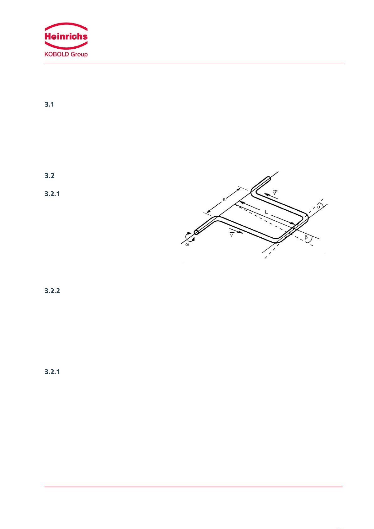
Measuring principle
The Coriolis mass flowmeter is based on the
principle whereby in a rotating system a force
(known as the Coriolis force) is exerted on a
mass at a rotation point that is moving towards
or away from this point.
System configuration
The flowmeter consists of a sensor that is mounted in a pipe, and a transmitter (see Section 4.1 Application
domain of the UMC3 transmitter on page 33), that can be directly mounted on the sensor or installed
separately (e.g. on a wall).
The transmitter oscillates the flow tubes in the sensor over an excitation coil and picks up, via the sensor coil,
the measuring signal, which is proportional to the mass flow. After being temperature compensated, the
measuring signal is converted into an analog output signal that is consistent with the measuring range setting.
Acquisition
Measured variables: Mass flow,
Density,
Temperature
Calculated variables: Volume flow
mFC2

Heinrichs Messtechnik GmbH
OPERATING MANUAL TMU / UMC3
Page 13 of 122
Performance characteristics of the TMU sensor
Reference conditions
Established flow profile
Inlet section has to correspond to mounting length
Control valves always positioned downstream
Measurement is to be performed with a liquid containing no gas bubbles
Flow tubes are to be kept clean at all times
Process temperature is to be regulated as specified in Section 3.4.6, “Process conditions” on page 22
Process pressure is to be regulated as specified in Section 3.4.8, “Process pressure range” on page 23
Ambient temperature is to range from + 10 °C to + 30 °C (50 °F to 86 °F)
Warm-up period: 15 minutes
Standard calibration is to be performed at 20 %, 50 % and 100 % (two times each)
High-frequency interference is to be regulated according to the EMC standards stated in section 9,
“Declaration of Conformity” on page 119
TMU flow ranges
Model kg/h [lbs/min] kg/h [lbs/min] kg/h [lbs/min] kg/h [lbs/min]
TMU-x008 60 [2,2] 600 [22,0] 330 [12,1] 0,03 [0,001]
TMU-x010 250 [9,2] 2500 [91,9] 1150 [42,3] 0,125 [0,005]
TMU-x012 800 [29,4] 8.000 [293,9] 3.650 [134,1] 0,4 [0,015]
TMU-x015 1200 [44,1] 12000 [440,9] 5250 [192,9] 0,6 [0,022]
TMU-x020 2.500 [91,9] 25.000 [918,6] 14.250 [523,6] 1,25 [0,046]
TMU-x025 3000 [110,2] 30000 [1102,3] 20000 [734,9] 1,5 [0,055]
TMU-x040 6000 [220,5] 60000 [2204,6] 55000 [2.020,9]* 3[0,110]
TMU-x050 20000 [734,9] 80000 [2939,4] 74000 [2.719,0] 4[0,147]
TMU-x080 25000 [918,6] 120000 [4409,2] 118000 [4.335,7]** 12 [0,4]
TMU-x100 30000 [1102,3] 200000 [7348,6] 200000 [7.348,6]*** 20 [0,7]
TMU-x150 60000 [2204,6] 460000 [16901,8] 460000 [16.901,8]*** 46 [1,7]
TMU-x200 150000 [5511,5] 700000 [25720,2] 700000 [25.720,2]**** 70 [2,6]
TMU-x250 300000 [11022,9] 1500000 [55114,6] 1350000 [49.603,2] 150 [5,5]
TMU-x300 400000 [14697,2] 2200000 [80834,8] 1900000 [69.811,9] 220 [8,1]
* (Dp=0,87bar)
** (Dp=0,95bar)
*** (Dp=0,93bar)
**** (Dp=0,66bar)
Zero point stability
(of range)
Max.
measuring range
Nominal
(Dp=1bar)
Min.
measuring range
Table 1: Flow ranges
Reference conditions: in conformity with IEC 770:
Temperature: 20 °C, relative humidity: 65 %, air pressure: 101.3 kPa
Fluid: water

Heinrichs Messtechnik GmbH
Page 14 of 122
OPERATING MANUAL TMU / UMC3
Density measurement
The attainable accuracy depends on the type of performed density calibration, selected during the ordering
process.
Note:
Without calibration no density measurement is possible and the empty pipe
recognition is not available.
Model without Calibration 3-Point 5-Point
TMU-x008 5 g/l 2 g/l
TMU-x010 5 g/l 2 g/l
TMU-x012 5 g/l 1 g/l
TMU-x015 5 g/l 1 g/l
TMU-x020 5 g/l 1 g/l
TMU-x025 5 g/l 1 g/l
TMU-x040 5 g/l 1 g/l
TMU-x050 5 g/l 2 g/l
TMU-x080 5 g/l 2 g/l
TMU-x100 5 g/l 2 g/l
TMU-x150 5 g/l 2 g/l
TMU-x200 5 g/l 2 g/l
TMU-x250 5 g/l 2 g/l
TMU-x300 5 g/l 2 g/l
Density accuracy
No
Density
measurement
possible
Table 2: Density accuracy

Heinrichs Messtechnik GmbH
OPERATING MANUAL TMU / UMC3
Page 15 of 122
Accuracy
Mass flow
Fluids
Accuracy TMU-x008 bis TMU-x050
± 0.1 % of actual flow ± zero point stability (1)
Accuracy TMU-x080 bis TMU-x300
± 0.15 % of actual flow ± zero point stability (1)
Repeatability error
± 0.05 % of actual flow (sensor with transmitter) ± ½ zero point
stability (1)
Mass flow
Gases
Accuracy TMU-x008 bis TMU-x050
± 0.5 % of actual flow ± zero point stability (1)
Accuracy TMU-x080 bis TMU-x300
± 0.5 % of actual flow ± zero point stability (1)
Repeatability error
± 0.25 % of actual flow (sensor with transmitter) ± ½ zero point
stability (1)
Additional measured values
Volume flow
± 0.2 % of actual value + zero point stability
Temperature
± 0.5 °C
Hysteresis
Not applicable
Settling time
1 to 15 seconds
Startup drift
15 minutes
Long-term drift
± 0.02 % of upper-range value per year
Influence of ambient temperature
± 0.005 % per K
Influence of fluid temperature
Compensated
Influence of fluid pressure
For fluids: too small to be relevant
(1) Refer to section 3.3.2, “TMU flow ranges” for detailed information on flow ranges.
Table 3: Measurement Deviation

Heinrichs Messtechnik GmbH
Page 16 of 122
OPERATING MANUAL TMU / UMC3
Pressure loss TMU
Model
Min.
measuring range
Max.
measuring range
60 kg/h 150 kg/h 300 kg/h 450 kg/h 600 kg/h
0,03 bar 0,15 bar 0,55 bar 1,18 bar 2,01 bar
250 kg/h 625 kg/h 1250 kg/h 1875 kg/h 2500 kg/h
0,05 bar 0,28 bar 1,02 bar 2,20 bar 3,78 bar
800 kg/h 2000 kg/h 4000 kg/h 6000 kg/h 8000 kg/h
0,05 bar 0,29 bar 1,06 bar 2,32 bar 4,02 bar
1200 kg/h 3000 kg/h 6000 kg/h 9000 kg/h 12000 kg/h
0,05 bar 0,29 bar 1,08 bar 2,38 bar 4,16 bar
2500 kg/h 6250 kg/h 12500 kg/h 18750 kg/h 25000 kg/h
0,04 bar 0,21 bar 0,84 bar 1,78 bar 3,29 bar
3000 kg/h 7500 kg/h 15000 kg/h 22500 kg/h 30000 kg/h
0,03 bar 0,16 bar 0,62 bar 1,38 bar 2,43 bar
6000 kg/h 15000 kg/h 30000 kg/h 45000 kg/h 60000 kg/h
0,01 bar 0,06 bar 0,23 bar 0,50 bar 0,89 bar
20000 kg/h 35000 kg/h 50000 kg/h 65000 kg/h 80000 kg/h
0,09 bar 0,22 bar 0,49 bar 0,73 bar 1,09 bar
25000 kg/h 48750 kg/h 72500 kg/h 96250 kg/h 120000 kg/h
0,05 bar 0,17 bar 0,36 bar 0,62 bar 0,95 bar
30000 kg/h 72500 kg/h 115000 kg/h 157500 kg/h 200000 kg/h
0,02 bar 0,13 bar 0,31 bar 0,58 bar 0,93 bar
60000 kg/h 160000 kg/h 260000 kg/h 360000 kg/h 460000 kg/h
0,02 bar 0,12 bar 0,30 bar 0,58 bar 0,93 bar
150000 kg/h 287500 kg/h 425000 kg/h 562500 kg/h 700000 kg/h
0,03 bar 0,11 bar 0,25 bar 0,43 bar 0,66 bar
300000 kg/h 600000 kg/h 900000 kg/h 1200000 kg/h 1500000 kg/h
0,05 bar 0,21 bar 0,47 bar 0,87 bar 1,30 bar
400000 kg/h 850000 kg/h 1300000 kg/h 1750000 kg/h 2200000 kg/h
0,05 bar 0,20 bar 0,47 bar 0,85 bar 1,34 bar
Model
Min.
measuring range
Max.
measuring range
2,2 lbs/min 5,5 lbs/min 11,0 lbs/min 16,5 lbs/min 22,0 lbs/min
0,03 bar 0,15 bar 0,55 bar 1,18 bar 2,01 bar
9,2 lbs/min 23,0 lbs/min 45,9 lbs/min 68,9 lbs/min 91,9 lbs/min
0,05 bar 0,28 bar 1,02 bar 2,20 bar 3,78 bar
29,4 lbs/min 73,5 lbs/min 147,0 lbs/min 220,5 lbs/min 293,9 lbs/min
0,05 bar 0,29 bar 1,06 bar 2,32 bar 4,02 bar
44,1 lbs/min 110,2 lbs/min 220,5 lbs/min 330,7 lbs/min 440,9 lbs/min
0,05 bar 0,29 bar 1,08 bar 2,38 bar 4,16 bar
91,9 lbs/min 229,6 lbs/min 459,3 lbs/min 688,9 lbs/min 918,6 lbs/min
0,04 bar 0,21 bar 0,84 bar 1,78 bar 3,29 bar
110,2 lbs/min 275,6 lbs/min 551,1 lbs/min 826,7 lbs/min 1102,3 lbs/min
0,03 bar 0,16 bar 0,62 bar 1,38 bar 2,43 bar
220,5 lbs/min 551,1 lbs/min 1102,3 lbs/min 1653,4 lbs/min 2204,6 lbs/min
0,01 bar 0,06 bar 0,23 bar 0,50 bar 0,89 bar
734,9 lbs/min 1286,0 lbs/min 1837,2 lbs/min 2388,3 lbs/min 2939,4 lbs/min
0,09 bar 0,22 bar 0,49 bar 0,73 bar 1,09 bar
918,6 lbs/min 1791,2 lbs/min 2663,9 lbs/min 3536,5 lbs/min 4409,2 lbs/min
0,05 bar 0,17 bar 0,36 bar 0,62 bar 0,95 bar
1102,3 lbs/min 2663,9 lbs/min 4225,5 lbs/min 5787,0 lbs/min 7348,6 lbs/min
0,02 bar 0,13 bar 0,31 bar 0,58 bar 0,93 bar
2204,6 lbs/min 5878,9 lbs/min 9553,2 lbs/min 13227,5 lbs/min 16901,8 lbs/min
0,02 bar 0,12 bar 0,30 bar 0,58 bar 0,93 bar
5511,5 lbs/min 10563,6 lbs/min 15615,8 lbs/min 20668,0 lbs/min 25720,2 lbs/min
0,03 bar 0,11 bar 0,25 bar 0,43 bar 0,66 bar
11022,9 lbs/min 22045,9 lbs/min 33068,8 lbs/min 44091,7 lbs/min 55114,6 lbs/min
0,05 bar 0,21 bar 0,47 bar 0,87 bar 1,30 bar
14697,2 lbs/min 31231,6 lbs/min 47766,0 lbs/min 64300,4 lbs/min 80834,8 lbs/min
0,05 bar 0,20 bar 0,47 bar 0,85 bar 1,34 bar
TMU-x250
11022,9 lbs/min
55114,6 lbs/min
TMU-x300
14697,2 lbs/min
80834,8 lbs/min
TMU-x150
2204,6 lbs/min
16901,8 lbs/min
TMU-x200
5511,5 lbs/min
25720,2 lbs/min
TMU-x080
918,6 lbs/min
4409,2 lbs/min
TMU-x100
1102,3 lbs/min
7348,6 lbs/min
TMU-x250
300000 kg/h
1500000 kg/h
TMU-x300
400000 kg/h
2200000 kg/h
TMU-x150
60000 kg/h
460000 kg/h
TMU-x200
150000 kg/h
700000 kg/h
TMU-x080
25000 kg/h
120000 kg/h
TMU-x100
30000 kg/h
200000 kg/h
TMU-x008
60 kg/h
600 kg/h
2500 kg/h
TMU-x010
250 kg/h
80000 kg/h
TMU-x050
20000 kg/h
60000 kg/h
TMU-x025
TMU-x040
6000 kg/h
3000 kg/h
30000 kg/h
2204,6 lbs/min
TMU-x040
220,5 lbs/min
TMU-x025
1102,3 lbs/min
110,2 lbs/min
918,6 lbs/min
TMU-x008
2,2 lbs/min
22,0 lbs/min
TMU-x010
9,2 lbs/min
91,9 lbs/min
440,9 lbs/min
TMU-x015
44,1 lbs/min
2939,4 lbs/min
Pressure loss [water (20°C), 1 mPas]
Pressure loss [water (20°C), 1 mPas]
TMU-x050
734,9 lbs/min
TMU-x012
29,4 lbs/min
293,9 lbs/min
TMU-x020
91,9 lbs/min
TMU-x012
800 kg/h
8000 kg/h
TMU-x020
2500 kg/h
25000 kg/h
12000 kg/h
TMU-x015
1200 kg/h
Table 4: Pressure losses

Heinrichs Messtechnik GmbH
OPERATING MANUAL TMU / UMC3
Page 17 of 122
Environmental Conditions
Ambient temperature
−40 °C to + 60 °C (-40 °F to 140 °F), as special version up to 80 °C (176 °F).
Special cables and cable glands are required for temperatures below −20 °C (-4 °F) and above +70 °C (158 °F).
Storage temperature
−25 °C to + 60 °C (-13 °F to 140 °F), − 40 °C (-40°F) available as special version.
Climatic category
In conformity with IEC 654-1. Unsheltered class D locations with direct open-air climate.
Ingress protection
Sensor: IP 67 (NEMA 6), Transmitter: IP68 / 1 m for 24 hours (NEMA 6P) acc. to DIN EN 60529 with mounted
and sufficiently tightened approved cable glands.

Heinrichs Messtechnik GmbH
Page 18 of 122
OPERATING MANUAL TMU / UMC3
Operating conditions
Installation
The sensor is to be protected, wherever possible, against valves, manifolds and similar fittings that generate
turbulence. The sensor is to be installed in accordance with the following instructions.
Diagram showing flowmeter installation
Flowmeter installation: A = sensor, B = valve, C = pipe clamps and supports.
The sensor is not to be used to support a pipe or
other pipe components.
Do not install the sensor in suspended pipes.
Do not adjust the position of a pipe by pulling or
grasping the sensor.
Heinrichs Messtechnik GmbH
OPERATING MANUAL TMU / UMC3
Page 19 of 122
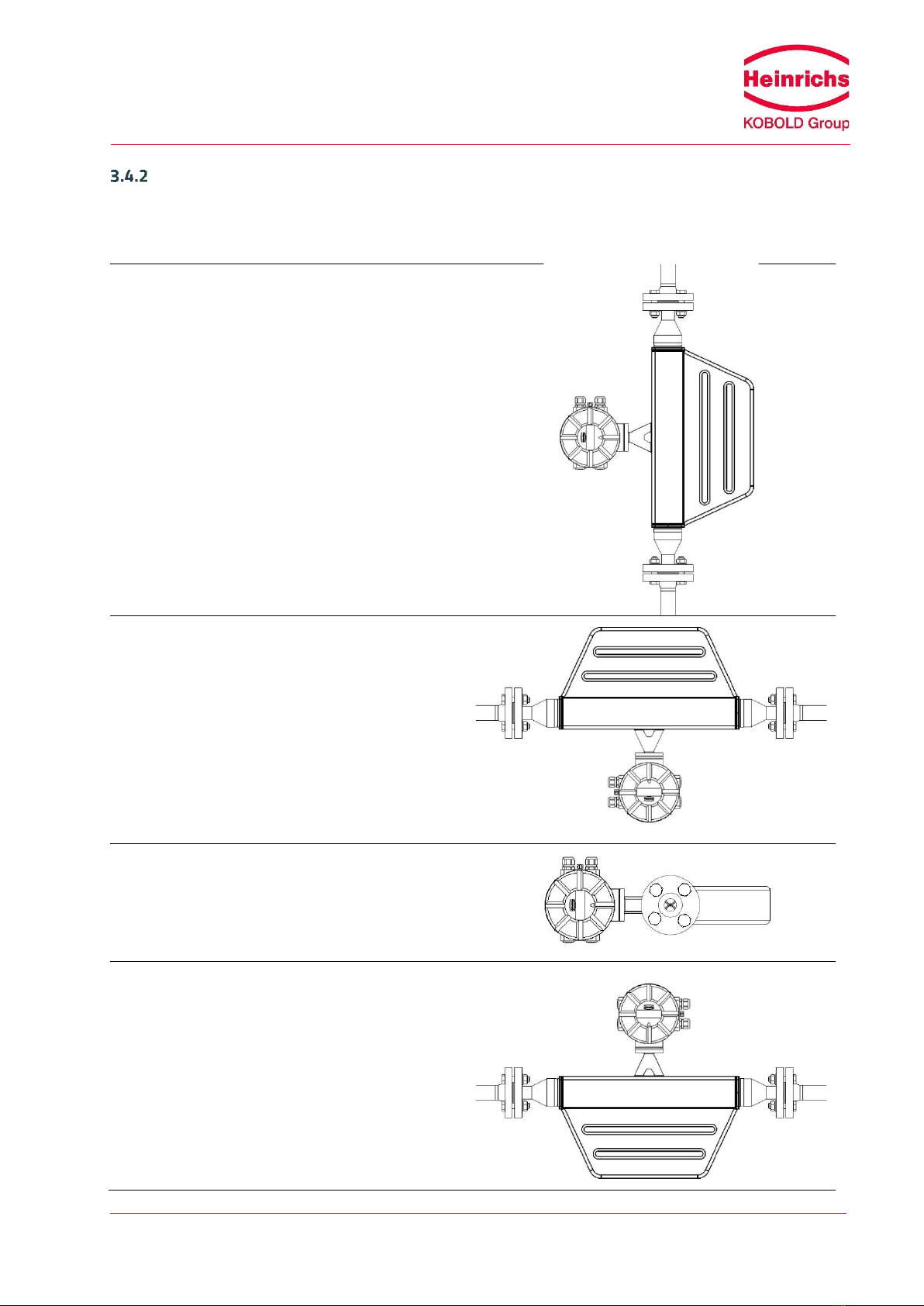
Installation Orientation
Without compromising its accuracy, the TMU can be installed and operated in various orientations. The
following representations show the most common installation positions and provide tips on how the operator
can prevent installation-related influences on the measurement.
Standard installation position
Installation position A
Installation position B
Installation position C

Heinrichs Messtechnik GmbH
Page 20 of 122
OPERATING MANUAL TMU / UMC3
Type of fluid
Position
Assessment
Pure liquids
Standard installation
position
Self-draining flow tubes
Position A or B
OK
Position C
Liquid residue remains in pipe
Liquids containing
homogeneously
dispersed gas
Standard installation
position
Self-draining flow tubes, gas bubbles do not accumulate in
flowmeter
Position A
Not recommended owing to gas bubble accumulation in
flowmeter
Position B
Gas bubbles may accumulate in the presence of low flow
velocities
Position C
No gas bubble accumulation in flowmeter, liquid residues
may remain in device after discharge
Liquids containing
substances that could
form deposits
Standard installation
position
Self-draining flow tubes, no deposit formation
Position A
OK
Position B
Substances in the liquid could form deposits at low flow
velocities
Position C
Not recommended owing to presence in flowmeter of
substances that could form deposits
Liquids containing
homogeneously
dispersed gas, which
may contain
substances that could
form deposits
Standard installation
position
Self-draining flow tubes, no accumulation of gases or
substances that could form deposits
Position A
Not recommended owing to gas bubble accumulation in
flowmeter
Position B
Gas bubbles or substances that could form deposits at low
flow velocities
Position C
Not recommended owing to presence in flowmeter of
substances that could form deposits
Gases that do not
form a condensate
Standard installation
position,
Position A, B or C
Any of these installations positions can be used
Gas, condensate-
forming gas/liquid,
moisture
Standard installation
position
Flow direction should be from top to bottom so that any
condensate that forms can flow out efficiently
Position A
OK
Position B
Condensate might form in flowmeter
Position C
Not recommended owing to condensate accumulation in
flowmeter
This manual suits for next models
14
Table of contents
Other Heinrichs Measuring Instrument manuals


