Heinrichs PITe-Series User manual
Installation and operating manual
Please read the instructions carefully and store them in a safe place
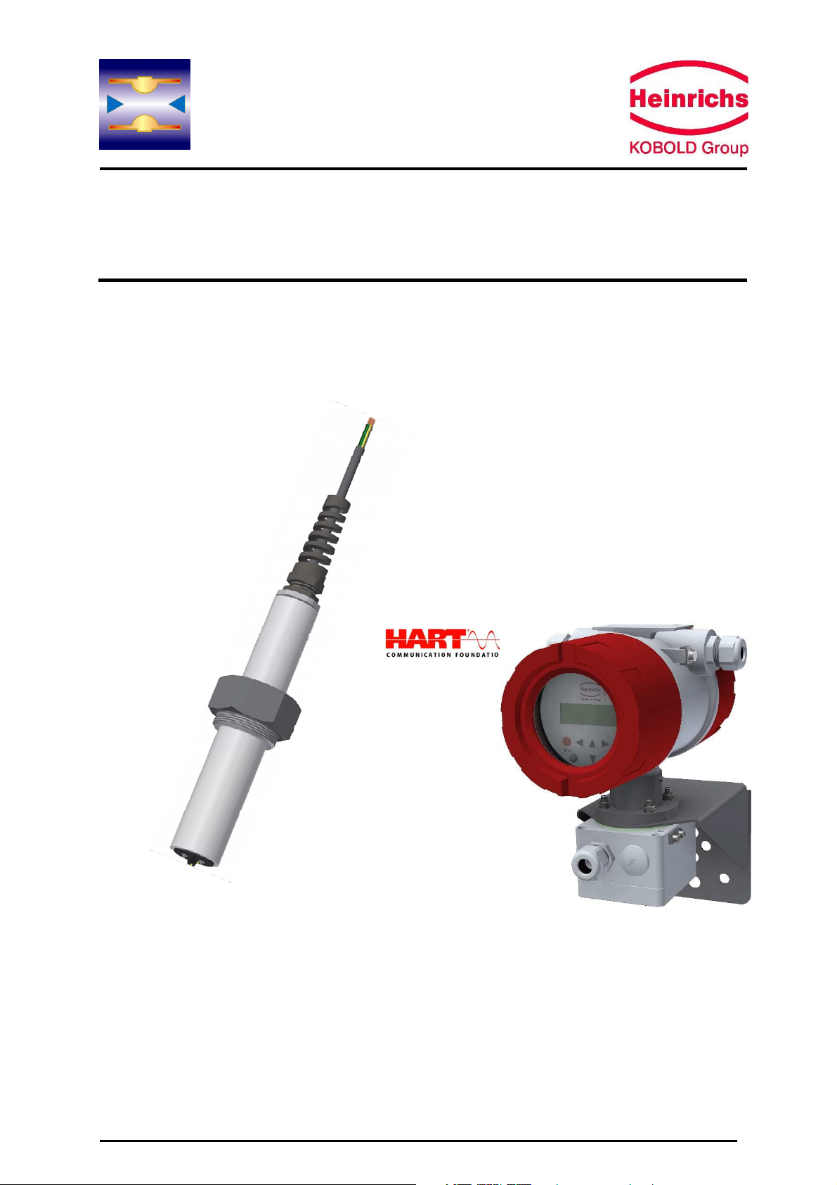
Magnetic-Inductive Flow Velocity Sensor
PITe with
UMF2 (B)

Heinrichs Messtechnik
Installation and Operation Manual
PITe
Page 2 of 22
Contents
1
INTRODUCTION ....................................................................................................................................... 4
1.1
H
AZARD WARNINGS
.......................................................................................................................................... 4
1.2
P
ACKAGING
/
STORAGE
/
TRANSPORT
................................................................................................................... 4
1.3
W
ARRANTY
..................................................................................................................................................... 5
2
IDENTIFICATION ...................................................................................................................................... 5
2.1
M
ANUFACTURER
/
SUPPLIER
................................................................................................................................ 5
2.2
P
RODUCT
........................................................................................................................................................ 5
3
USE IN HAZARDOUS AREAS ..................................................................................................................... 5
4
AREA OF APPLICATION ............................................................................................................................ 6
5
SAFETY ASPECTS DURING COMMISSIONING AND MAINTENANCE .......................................................... 6
5.1
U
SE OF THIS MANUAL AND TARGETED PERSONNEL
................................................................................................... 6
5.2
I
NTENDED USE OF THE DEVICE
............................................................................................................................. 6
5.3
I
NSTALLATION COMMISSIONING AND MAINTEINANCE
...............................................................................................
5.4
R
EPLACING THE TRANSMITTER ELECTRONICS
..........................................................................................................
5.5
R
ETURNING THE DEVICE FOR REPAIRS OR SERVICING
................................................................................................
6
MODE OF OPERATION AND SYSTEM DESIGN .......................................................................................... 8
6.1
M
ODE OF OPERATION
....................................................................................................................................... 8
6.2
S
YSTEM CONFIGURATION
................................................................................................................................... 8
6.3
I
NSTALLATION OF THE TRANSMITTER
.................................................................................................................... 8
6.3.1
Sensor versions ............................................................................................................................... 9
6.4
P
ERFORMANCE
C
HARACTERISTICS
........................................................................................................................ 9
7
INSTALLATION / CONDITIONS OF USE ................................................................................................... 10
.1
I
NSTALLATION REQUIREMENTS
.......................................................................................................................... 10
.1.1
Examples of installation positions ................................................................................................ 10
.1.2
Immersion depth of PITe-*** in the pipe ..................................................................................... 13
.1.3
Earthing – potential equalisation.................................................................................................. 13
.2
E
NVIRONMENTAL CONDITIONS
.......................................................................................................................... 14
.2.1
Ambient temperature ranges ....................................................................................................... 14
.2.2
Storage temperature .................................................................................................................... 14
.2.3
Climatic category .......................................................................................................................... 14
.2.4
Ingress Protection ......................................................................................................................... 14
.2.5
Shock resistance/vibration resistance .......................................................................................... 14
.2.6
Medium temperature and pressure ............................................................................................. 14
8
COMMISSIONING .................................................................................................................................. 14
8.1
I
NSTALLATION OF MAGNETIC
-
INDUCTIVE FLOWMETERS
.......................................................................................... 14
8.2
P
OTENTIALS
.................................................................................................................................................. 14
8.3
C
ATHODE PROTECTIVE UNITS
............................................................................................................................ 15
8.4
Z
ERO POINT CALIBRATION
................................................................................................................................ 15
STARTUP CONDITIONS .......................................................................................................................... 15
10
POWER SUPPLY / ELECTRICAL CONNECTION ......................................................................................... 17
10.1
E
LECTRICAL CONNECTION
................................................................................................................................. 1
10.2
C
ABLE SPECIFICATION
...................................................................................................................................... 1
11
DIMENSIONS/WEIGHT .......................................................................................................................... 18
11.1
D
IMENSIONAL DRAWINGS
................................................................................................................................ 18
12
DECLARATION OF DECONTAMINATION................................................................................................. 1

Heinrichs Messtechnik
Installation and Operation Manual
PITe
Page 3 of 22
13
DECLARATION OF CONFORMITY ........................................................................................................... 20
14
FINAL NOTES ......................................................................................................................................... 22

Heinrichs Messtechnik
Installation and Operation Manual
PITe
Page 4 of 22
1 Introduction
It is essential that you read these installation and operating instructions, as well
as the associated UMF2 (B) transmitter operating instructions, prior to
installation and commissioning of the device. If the necessary operating manuals
are not at hand, you can download them free of charge from www.heinrichs.eu.
The device is to be installed and serviced only by a qualified technician.
Custom designs and special applications are not be addressed in this manual.
All devices are thoroughly tested and checked for order compliance and functionality prior to shipping.
If however you have any queries or problems concerning your purchased product, please contact our
head office in Cologne.
Heinrichs Messtechnik GmbH accepts no liability for any loss or damage of any kind arising
from improper operation of any product, improper handling or use of any replacement part, or
from external electrical or mechanical effects, overvoltage or lightning. Any such improper
operation, use or handling shall automatically invalidate the warranty for the product
concerned.
1.1 Hazard warnings
The purpose of the hazard warnings listed below is to ensure the safety of the device operators and
maintenance personnel, and that the flowmeter and any devices connected to it are not damaged.
The safety advisories and hazard warnings in this document are defined in the four categorised terms
below, and are aimed to prevent putting operators and maintenance personnel at risk, or to avoid
material damage. The used terms have, with respect to this document and the products described
within, the following meanings:
Danger
means that failure to take the prescribed precautions will result in death, severe bodily injury, or
substantial material damage.
Warning
means that failure to take the prescribed precautions could result in death, severe bodily injury, or
substantial material damage.
Caution
means that failure to take the prescribed precautions could result in incorrect operation, malfunction
or damage to the device.
Note
means that the accompanying text contains important information about the product, handling of the
product or is about a section of the documentation that is of particular importance.
1.2 Packaging / storage / transport
Your flowmeter was manufactured in accordance with the highest quality standards and was
thoroughly tested prior to shipment. Upon receipt, please conduct a visual inspection for possible
damage that may have occurred during shipment. If you discover any transit damage, please contact
our head office in Cologne or the local sales office responsible for your area immediately. Besides a
fault description, the type of device in question and its serial number will be required for any claim.
Heinrichs Messtechnik shall not furnish guarantee for any repair work done without prior notice.
Unless otherwise agreed on, the rejected parts must be made available to us in case a claim is made.

Heinrichs Messtechnik
Installation and Operation Manual
PITe
Page 5 of 22
1.3 Warranty
Your flowmeter was manufactured in accordance with the highest quality standards and was
thoroughly tested prior to shipment. However, in the event any problem arises with your device, we will
be happy to resolve the problem for you as quickly as possible under the terms of the warranty which
can be found in the terms and conditions of delivery. Your warranty will only be honoured if the device
was installed and operated in accordance with the instructions for your device. Any mounting,
commissioning and/or maintenance work is to be carried out by qualified and authorised technicians
only.
Heinrichs Messtechnik GmbH extends no express or implied warranty in regard to the applicability of
the present document for any purpose other than that described.
2 Identification
2.1 Manufacturer/supplier
Heinrichs Messtechnik GmbH
Robert-Perthel-Str. 9 ⋅D-50739 Cologne
Phone: +49 (221) 49708 – 0, Fax: +49 (221) 49708 - 178
Internet: http://www.heinrichs.eu, e-mail: mailto:info@heinrichs.eu
2.2 Product
Product type:
Magnetic – inductive flow sensor based upon Faraday’s law of induction
Application:
Bi-directional measurement of fluids with a minimum conductivity of 50µS / cm
Product name:
PITe-xxx
File version No.:
DRAFT-PITE_BA_02_EN_25-01-2017
Issue date:
17.02.2017
Converting Transmitters:
UMF2 (B)
3 Use in hazardous areas
The flow meter PITe-xxx is not intended for use in hazardous areas.
Heinrichs Messtechnik
Installation and Operation Manual
PITe
Page 6 of 22
4 Area of application
The magnetic-inductive flow velocity sensor PITe is be used to measure or monitor the volume flow of
liquids with and without solids concentration, slurries, pastes and other electrically conductive media
while minimizing pressure drops. The conductivity of the medium must be at least 50 µS/cm. Pressure,
temperature, density and viscosity do not affect the volume measurements. Small quantities of solid
particles and small gas bubbles are also measured as part of the volume flow. A larger number of
solid particles or gas bubbles will lead to incorrect measurements. Special electrodes are available for
media that tend to form greasy films or crusts.
To perform flow measurements, the PITe sensor must be operated with a Heinrichs Messtechnik
transmitter of the UMF-x series, for example the UMF2 (B). The transmitter UMF2 (B) is a
programmable transmitter that process the measurement data received from the sensor displaying the
results on it’s built in control panel. Furthermore, it is capable of transmitting various types of
measurement results via a communication interface.
5 Safety aspects during commissioning and maintenance
5.1 Use of this manual and targeted personnel
This document contains all the necessary information to ensure a correct operation of the herein
described product. The document is intended for use by qualified personnel. This means personnel
who possess the necessary knowledge needed to ensure a safe operation of the device, such as
electronics engineers, electrical engineers, or service technicians who are conversant with the safety
regulations pertaining to the use of electrical and automated technical devices.
Such personnel must be authorized by the facility operator to install, commission and service the
product described herein. Before any work is carried out on the device, these operating instructions
must first be thoroughly read and understood.
The principle rules and regulations in the country of the operator must be observed.
5.2 Intended use of the device
Warning
The operator is responsible for ensuring that the material used in the sensor and
housing is suitable for the application, and that such material meets the
requirements for the fluid being used and the ambient site conditions. The
manufacturer accepts no responsibility when inadequate material and housing are
ordered.
Warning
To ensure a correct and safe operation of the device, it must be shipped, stored,
set up, mounted, operated and maintained correctly.
Heinrichs Messtechnik
Installation and Operation Manual
PITe
Page 7 of 22
5.3 Installation commissioning and maintenance
The devices described in this manual are to be installed and serviced only by qualified technical
personnel such as a qualified Heinrichs Messtechnik electronics engineer or service technician.
Warning
Before servicing, the device must be completely deenergised and disconnected from
all peripheral devices. The technician must also check to ensure that the device is
completely off-circuit. Only original replacement parts are to be used.
5.4 Replacing the transmitter electronics
Before replacing the transmitter electronics, read first the safety instructions in this section.
Warning
Make sure that you abide by the applicable standards and regulations pertaining to
electrical devices, device installation and process technology when replacing the
transmitter electronics. The highly integrated electronic components in the device
carry the risk of ESD hazards and are only protected when installed in the device
pursuant to EMC standards.
Caution
The complete electronic stack is to be replaced with all of its printed circuit boards
(except for the memory chip (DSM)). The specified precision and interchangeability of
the electronics are only guaranteed if the electronic stack is replaced as a whole.
Heinrichs Messtechnik GmbH accepts no liability for loss or damage of any kind arising from improper
operation of any product, improper handling or use of any replacement part, or from external electrical
or mechanical effects, overvoltage or lightning. Any such improper operation, use or handling shall
automatically invalidate the warranty for the product concerned.
In the event a problem arises with your device, please contact us at one of the following numbers to
arrange to have your device repaired:
Phone: +49 221 49708-0
Fax: +49 221 49708-178
Contact our customer service department if your device requires repair or if you need assistance in
diagnosing a problem.
5.5 Returning the device for repairs or servicing
Note: According to German waste disposal legislation, it is the owner’s or customer’s responsibility to
dispose of hazardous waste. Thus, before any devices are returned to Heinrichs Messtechnik for
servicing or repairs the following measures must be performed:
•When returning the unit for an inspection, please enclose as detailed a description as possible
of the fault and the specific application, as well as the chemical-physical properties of the
measurement medium.
•Remove all residue of measurement medium which may be present. paying special attention
to the gasket grooves and crevices. This is especially important if the medium is detrimental to
health and safety, for example: corrosive, poisonous, carcinogenic or radioactive etc.
•Costs, which result from insufficient cleaning, (disposal and/or personal injuries) will be
invoiced to the customer.
A decontamination certificate, to be found in section 12 “Declaration of Decontamination“, must be
completed and enclosed in the return delivery!

Heinrichs Messtechnik
Installation and Operation Manual
PITe
Page 8 of 22
6 Mode of Operation and System Design
6.1 Mode of operation
Back in 1832, Faraday suggested utilizing the principle of electromagnetic induction for measuring
flow velocities. Though unsuccessful due to superimposed polarization effects, his experiments on the
river Thames are nonetheless regarded as the first in the field of magnetic-inductive flow
measurement.
According to Faraday’s law of electromagnetic induction, an electrical field Eis produced in a
conductive liquid when moving through a magnetic field Bat a velocity vin accordance with the vector
product E = [v x B].
A liquid at flow velocity vand a flow rate Qflows through a meter tube (4) producing a measuring-
circuit voltage Um at the two electrodes (E1 and E2), which are positioned at right angles to the
direction of flow and the magnetic field Bgenerated by the field coils (3). The size of the measured
voltage is proportional to the mean flow velocity and thus the volume flow rate.
6.2 System configuration
The magnetic-inductive PITe-UMF2 (B) flow measurement system consists of a sensor (PITe), which
picks up an induced measuring signal from the medium flowing through the pipe with a known
diameter, and the transmitter UMF2 (B), which transforms this signal into standardized output signals
(4-20 mA or pulses).
The PITe-*** sensor can be operated with all transmitters for magnetic-inductive flow meters
manufactured by Heinrichs Messtechnik. The sensor is installed in the pipe while the transmitter is
mounted separately in the field for better access.
6.3 Installation of the transmitter
The sensor is equipped with a breakout cable and must be connected to the transmitter via a junction
box fitted during installation. The electrode cable is shielded and protected against disturbing
interferences.
The required cable length for the connection to the transmitter must be determined during ordering.
The end of the delivered break-out cable is prepared for an optimal and easy direct connection to the
transmitters junction box. A subsequent shortening or lengthening of the cable could cause EMC and/
or measurement issues if not correctly implemented, for which Heinrichs Messtechnik GmbH shall
take no responsibility.

Heinrichs Messtechnik
Installation and Operation Manual
PITe
Page 9 of 22
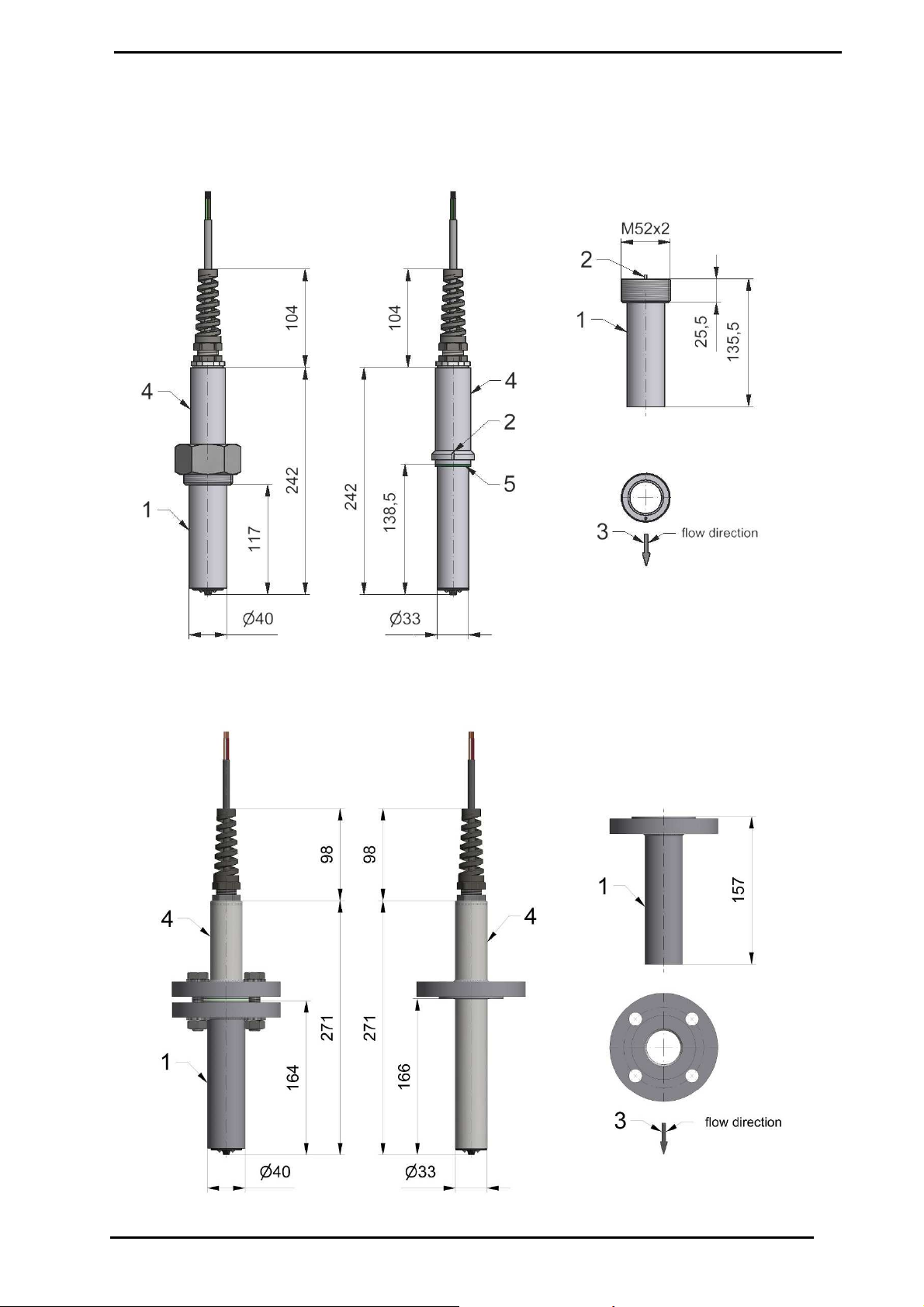
6.3.1 Sensor versions
PITe Wetted parts stainless steel / Hastelloy / PTFE,
Sensor neck connection: union nut (threaded version) or flange stainless steel
Threaded version Flanged version (Option)
Weld-on adaptor Ø40mm with Weld-on adaptor Ø40mm with
M52x2 sensor locking with rotation lock DN25 PN40 Form B1 DIN/EN1092
1” JIS 16K
1“ class 150/300RF ASME B16.5
6.4 Performance Characteristics
Measurement accuracy:
Q ≥30% FS: ±1.5 % of actual range
Q ≤30% FS: ±1.5 % of actual range ±2.5 % of FS
Medium Conductivity:
≥50 µS/cm
Influence of the ambient temperature on the outputs:
Pulse output ±0, 05% pro 10K
Current output ±0, 1% pro 10K
Influence of medium temperature:
None
Influence of ambient temperature
See Operating Instructions of the UMF2 (B) transmitter
Heinrichs Messtechnik
Installation and Operation Manual
PITe
Page 10 of 22
7 Installation / Conditions of use
7.1 Installation requirements
Screws, bolts, nuts and seals are not supplied by Heinrichs Messtechnik GmbH and must therefore be
provided by the operator. So not to damage any part of the sensor during installation, only use tools
specifically designed for intended purpose.
7.1.1 Examples of installation positions
To ensure the indicated accuracy, the installation must be performed according to EN 29104
"Measurement of Fluid Flow in Closed Conduits – Methods of Evaluating the Performance of
Magnetic-Inductive Flow meters." Based on this standard, the minimum straight run of pipe ahead of
the inlet must be 10 pipe diameters (≥10 x DN) and 5 pipe diameters following the outlet (≥5 x DN)
[DN = nominal diameter of pipe].
The limits for the product and ambient temperature must be met at the mounting location. Corrosive
atmospheres must be avoided.
Before installing the device in the pipeline, Please consider the space requirements
needed for a potential deinstallation of the device.
Horizontal pipeline routing
Where possible install the sensor in slightly ascending pipes. This practice will minimise the possibilies
of air pockets or drainage of the installation pipe.
In the top section of the pipe, air pockets may accumulate around the sensor head causing large
fluctuatios in the measurement. In declining sections of the pipeline, pipes may drain, also generating
errors in the measurement.

Heinrichs Messtechnik
Installation and Operation Manual
PITe
Page 11 of 22
Open inlet or outlet
When installed at an inlet or an outlet, the device should be installed, where possible, in a siphon. This
will ensure that the pipe section fitted with the sensor cannot autonomously drain. The empty pipe
detection circuit of the transmitter is an additional safety feature for recognizing empty or partially filled
pipes.
Caution! There is the danger of accumulation of solids in the vacinity of a siphon. The installation of a
cleaning aperture in the pipe is therefore advisable.
Down pipes
When down pipes are present in the pipe system, a siphon or a ventilation valve should be positioned
after the sensor. By these means, negative pressure can be avoided in the pipeline, preventing a
breakdown of the flow thus reducing the risk of air inclusions in the measurement medium.

Heinrichs Messtechnik
Installation and Operation Manual
PITe
Page 12 of 22
Long pipelines
In long pipelines, there is always a danger of pressure surges. Therefore, disturbing elements such as
regulating and shut-off devices should be arranged downstream from the sensor. However, when
installed in vertical piping, especially when operating at high temperatures, the regulating and shut-off
devices should be placed in front of the sensor (danger of vacuum).
If this is impracticle, flow conditioners must be installed so that no vortexes can reach the pipe section
of the sensor. The mounting location in the pipe system should be selected so that the installation pipe
with the sensor is continually filled with the medium. This requirement can be met by using drains and
check valves.
Installation of pumps
To avoid negative pressure and eventual damage to the sensor head, never install PITe flowmeters on
the suction side of pumps.
If necessary, arrange for pulsation dampeners when using piston, diaphragm or hose pumps.
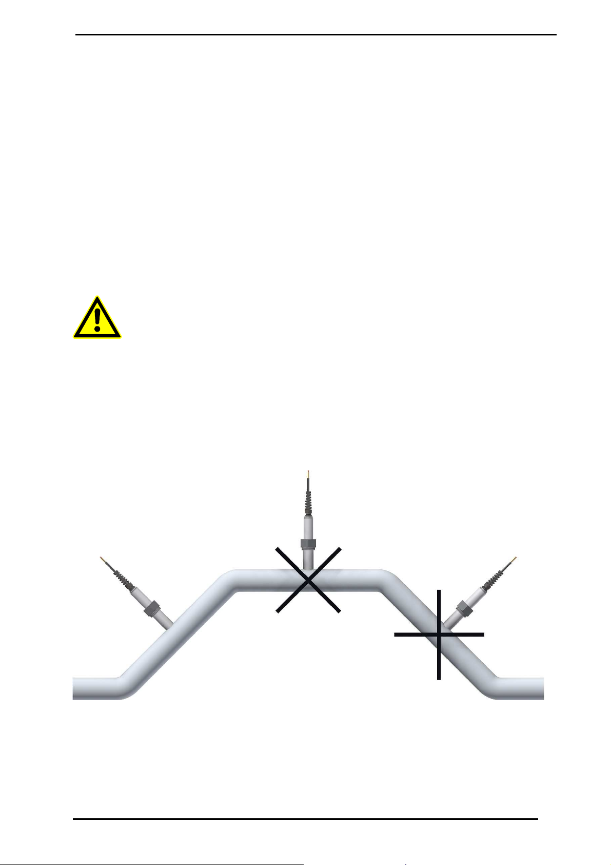
Preferred mounting position
To avoid possible sources of error, the mounting position of the
sensor should be carefully chosen.
The ideal angle of installation should lie between 45° and 135°.
When Installed at the top of the pipe (0 °C), gas bubbles may gather
around the sensor head causing large fluctuations in the
measurement signals, whereas sensors installed at the bottom of a
pipe (180 °C) may be affected by sediment deposed in the pipe.

Heinrichs Messtechnik
Installation and Operation Manual
PITe
Page 13 of 22
7.1.2 Immersion depth of PITe-*** in the pipe
The weld spigots must be installed so that the sensor head projects 40 mm into the pipeline,
regardless of the pipes nominal diameter.
Caution: Before welding the socket to the pipe, it is essential that the sensor be removed from the
welding socket!
Installing the threaded version
Installing the flanged version
7.1.3 Earthing – potential equalisation
The sound grounding concept of the flowmeter is a necessity for both safety reasons as well as to ensure
a faultless operation. In accordance with VDE 0100 Part 410 and VDE 0100 Part 540 the grounding
connections must be at protective conductor potential. For metrological reasons, this potential must
be identical to the potential of the fluid. The grounding cable should not transmit any interference
voltage. For this reason do not simultaneously ground other electrical devices with this cable.

Heinrichs Messtechnik
Installation and Operation Manual
PITe
Page 14 of 22
The measuring signal tapped at the electrodes amounts to only a few millivolts. Correct grounding of
the electromagnetic flow sensor is therefor essential for achieving exact measurement. The transmitter
requires a reference potential to evaluate the measured voltage on the electrodes. The metrological
grounding of the medium for PITe is achieved via the wetted part of the sensor tube.
7.2 Environmental conditions
7.2.1 Ambient temperature ranges
-20°C to +60°C, below 0°C the readability of the LCD becomes limited
7.2.2 Storage temperature
-20°C to +60°C
7.2.3 Climatic category
In accordance with IEC 654-1 Non weather-protected Class D locations exposed directly to open-air
climate
7.2.4 Ingress Protection
PITe sensor: IP65 (EN60529)
Caution:
Ingress protection IP65 can only be achieved if suitable and tightly secured cable
glands or conduits are used. If the cable glands are only tightened handtight,
water may
leak or seep into the terminal compartment of the housing.
Danger:
Action must be taken if the window of the transmitter enclosure
becomes fogged over or
discolored. This is a sure sign that moisture, water or product medium has seeped into
the terminal compartment of the housing, for example, through the cable sheath!
Warning:
Electromagnetic compatibility is only guaranteed if the electronic housing is sealed.
Leaving the enclosure open can lead to electromagnetic disturbances.
7.2.5 Shock resistance/vibration resistance
The meter should be protected against extreme shocks and vibrations larger than 1G, which may
cause damage to the sensor or transmitter.
7.2.6 Medium temperature and pressure
-20°C to +100°C, 16 bar up to 90°C, 14 bar up to 100°C
8 Commissioning
8.1 Installation of magnetic-inductive flowmeters
During the installation of the magnetic-inductive flow sensor the instructions and notes of the assembly
instructions and operating manuals have to be followed. The regulations guidelines of grounding,
potential equalization and company-internal grounding practices are also to be observed.
8.2 Potentials
The outputs of the UMF2 (B) transmitter are all electrically isolated from the auxiliary power, the
sensor circuit and from each other. The housing and the interference suppression filters of the power
supply are connected to PE.

Heinrichs Messtechnik
Installation and Operation Manual
PITe
Page 15 of 22
The electrodes and measuring electronic are referenced to the potential of the functional earth FE of
the sensor. FE is not connected to PE, but may be connected in the sensor junction box if wished. If
ground disks (earthing rings) are used for grounding purposes, then these must be connected to the
functional earth FE.
Since the sensor and transmitter are mounted separetely, the outer shield of the connecting cable
must be connected to the transmitter housing via the cable gland and has PE potential. The inner
shields of the electrode and exciter wires are connected to FE inside the junction box of the sensor
and sowith to the ground (Gnd) of the transmitters electronic.
8.3 Cathode protective units
When using a cathode protective unit to avoid corrosion, thus putting a voltage to the tube wall, the
unit must be connected to terminal FE. The transmitter electronic, control panel and internal switches
are also all referenced to the FE potential.
Warning
According to EN 50178:1997 all electrical circuits with ”protective safety isolation”
which do not possess
contact protection must observe the following maximum
voltages:
Maximum AC voltage (effective value) 25 VRMS
Maximum DC voltage 60 V
It is strictly forbidden to connect FE to a higher voltage!
8.4 Zero point calibration
To ensure precise measurements are obtained, zero point calibration is essential the first time the
device is put into operation and before any regular operations is carried out. To perform a zero point
calibration, the sensor head must be inserted approx. 40mm into the medium to be measured (see
section 7.1.2 “Immersion depth of PITe-*** in the pipe” on page 13
The zero calibration procedure is as follows:
- Install the sensor as described in the manufacturer’s instructions.
- Ensure that the sensor head is completely covered with fluid and that there are no gas
bubbles in the pipe around the sensor head.
- Define the process conditions such as pressure, temperature and density.
- Close a potential shut-off device behind the sensor.
- Turn on the transmitter and ensure that sufficient time is allowed for the electronics to warm
up (20 minutes as a general rule).
- Initiate the Zero point calibration sequence over the transmitter in accordance with the
appropriate transmitter-operating manual.
Allowing fluid to flow through the sensor during the zero calibration procedure will skew the zero point
and result in false future readings.
9 Startup conditions
The device is not subject to specific startup conditions. However, pressure surges should be avoided.
To ensure the transmitter correctly calculates the measured volume flow velocity, it is essential to
ensure that during commissioning of the PITe series of sensors, the installation requirements,
regarding position and mounting depth, are correctly adhered to.

Heinrichs Messtechnik
Installation and Operation Manual
PITe
Page 16 of 22
If the calibration of the sensor / UMF2 (B) transmitter combination has not been
performed by the manufacturer, the necessary settings must be implemented in
the transmitter before the sensor can operate correctly. This applies in particular to
cases where the sensor has been exchanged, or when the pipe cross-section at
the installation site is altered.
Heinrichs Messtechnik
Installation and Operation Manual
PITe
Page 17 of 22
10 Power supply / electrical connection
See name plate or Operating Instructions of the UMF2 (B) transmitter.
10.1 Electrical connection
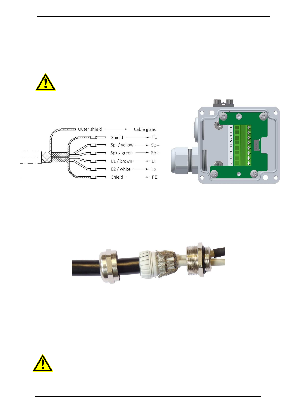
The outer shield must be connected to the “PE” Terminal. The inner shields are each to be connected
to there respective “FE” terminal.
Caution: When placing the blank shield wires into the respective terminals, take care not
to cause short circuits.
Connecting the sensor cable to the terminal box of the
UMF2 (B) transmitter
Connecting the cable shield in the cable gland
To abide to EMC requirements, the outer shield of the cable must be unbraided, folded back over the
plastic insert and cut to length as can be seen in the graphic below. The unbraided strands must lie
over the O-ring whos function it is to press the braids of the outer shield onto the metal cable gland.
This O-ring does not serve the purpose of a sealant.
10.2 Cable specification
The following interconnecting cable is used:
The Electrodes and exciter coil are connected using shielded twisted pair wires which have a wire
cross section of 0,75mm² e.g. SLIYCY-C11Y ( 2x ( 2x 0.75mm²)). To protect the cable from external
interferences, an additional outer shield covers the twisted-pair wires.
The twisted pair shields are connected to the FE terminals in the junction box of the transmitter, and
the outer shield is grounded by means of the special EMC-compliant cable gland of the junction box.
Caution:
Do not connect or disconnect the exciter coil cable to the transmitter before the main power
supply of the meter has been disconnected!
Heinrichs Messtechnik
Installation and Operation Manual
PITe
Page 18 of 22
11 Dimensions/weight
11.1 Dimensional drawings
Threaded version (standard)
Flanged version (optional)

Heinrichs Messtechnik
Installation and Operation Manual
PITe
Page 19 of 22
12 Declaration of Decontamination
for the cleaning of the device
Company: ...................................... Town/City: ..........................................
Department: .................................. Name: ................................................
Tel.-N
o
.: ........................................
The enclosed flowmeter
Model: PITe........................
Was operated using the following fluid: .................................................................
Since the used fluid is potentially hazardous to water / toxic / corrosive /
combustible*,
we have:
-
checked all cavities on the device to ensure that they are free of fluid residues *
-
washed and neutralized all cavities on the device*
* Delete if not applicable.
We hereby confirm that no health or environmental hazard will arise from any fluid
residues on or in the device enclosed for return.
Date: ............................. Signature: ...........................
Company stamp

Heinrichs Messtechnik
Installation and Operation Manual
PITe
Page 20 of 22
13 Declaration of Conformity
Konformitätserklärung
Declaration of Conformity
N
o
. 16.4149.01
Hersteller:
Manufacturer:
Heinrichs Messtechnik GmbH
Robert-Perthel-Strasse 9
50739 Köln
Produktbeschreibung:
Product description:
Magnetisch Induktiver Durchflussmessgerät UMF2 (B) für
Verwendung mit der Sensorreihe PIT* und PITe*
Magnetic inductive flowmeter UMF2 (B) for use with the
sensor series PIT* and PITe*
Hiermit erklären wir, in alleinige Verantwortung, dass das
oben genannte Messsystem den Anforderungen der
folgenden EU-Richtlinien, einschließlich allen bis heute veröffentlichten Änderungen bzw. Nachträgen
entspricht:
We declare herewith, in sole responsibility, that the product described above is conform with the provisions of
the following EU-directives, including all published changes and amendments as of today:
2014/30/EU (EMC) EU-Richtlinie über die Elektromagnetische Verträglichkeit
EU-Directive relating to electromagnetic compatibility
2014/35/EU (LVD) EU-Richtlinie über die Bereitstellung elektrischer Betriebsmittel zur
Verwendung innerhalb bestimmter Spannungsgrenzen auf dem Markt
EU-Directive relating to the making available on the market of electrical
equipment designed for use within certain voltage limits
Anhang N ist ein integraler Bestandteil dieser Erklärung
Annex N is an integral part of this declaration
Köln, den 27.01.2017
Frank Schramm
(Geschäftsführung /
Managing Director)
Kontakt: Tel: +49 (221) 49708-0
Contact: Email: [email protected]
Web: www.heinrichs.eu
This manual suits for next models
1
Table of contents
Other Heinrichs Measuring Instrument manuals


Popular Measuring Instrument manuals by other brands


ATIM
ATIM ACW-DI2/868 installation guide

Merck
Merck Allflex AWR250 Quick start up guide

Makita
Makita LD100P instruction manual

Spectrum Technologies
Spectrum Technologies Lightscout 3413F product manual

Utility Solutions
Utility Solutions USJL-002 Operation manual

SATO KEIRYOKI
SATO KEIRYOKI SK-181GT instruction manual


