HEKA LIH 1600 User manual

Manual 1.0
LIH 1600
Acquisition Interface

HEKA Elektronik Phone +49 (0) 6325 / 95 53-0
Dr. Schulze GmbH Fax +49 (0) 6325 / 95 53-50
Wiesenstrae 71 Web Site http://www.heka.com
D-67466 Lambrecht/Pfalz Email sales@heka.com
Germany support@heka.com
HEKA Electronics Inc. Phone +1 902 624 0606
47 Keddy Bridge Road Fax +1 902 624 0310
R.R. #2 Web Site http://www.heka.com
Mahone Bay, NS B0J 2E0 Email nasales@heka.com
Canada support@heka.com
HEKA Instruments Inc. Phone +1 866 742 0606 (Toll Free)
33 Valley Road Fax +1 508 481 8945
Southboro, MA 01772 Web Site http://www.heka.com
USA Email nasales@heka.com
support@heka.com
Title Page: LIH 1600 Acquisition Interface
©
2004 HEKA Elektronik Dr. Schulze GmbH
COMDLH/1

Contents
1 Description of the Hardware 1
2 Technical Specifications 3
2.1 Analog Inputs . . . . . . . . . . . . . . . . . . . . . . . . . . 3
2.2 “Telegraphing” Inputs . . . . . . . . . . . . . . . . . . . . . 3
2.3 Digital Inputs . . . . . . . . . . . . . . . . . . . . . . . . . . 3
2.4 Trigger Inputs . . . . . . . . . . . . . . . . . . . . . . . . . . 4
2.5 Analog Outputs . . . . . . . . . . . . . . . . . . . . . . . . . 4
2.6 Digital Outputs . . . . . . . . . . . . . . . . . . . . . . . . . 4
2.7 Connectors . . . . . . . . . . . . . . . . . . . . . . . . . . . 5
2.8 Dimensions . . . . . . . . . . . . . . . . . . . . . . . . . . . 5
2.9 Cable .............................. 5
2.10 Warranty . . . . . . . . . . . . . . . . . . . . . . . . . . . . 5
3 Installation 7
3.1 Connecting the Lih 1600 . . . . . . . . . . . . . . . . . . . . 7
3.2 Software Installation . . . . . . . . . . . . . . . . . . . . . . 9
3.2.1 Windows NT 4.0, Windows 2000, and Windows XP 9
3.2.2 Windows 98 . . . . . . . . . . . . . . . . . . . . . . . 10
3.2.3 MacOS 9.x . . . . . . . . . . . . . . . . . . . . . . . 10
3.2.4 Mac OS X . . . . . . . . . . . . . . . . . . . . . . . . 11

ii CONTENTS
4 Controls and Functions 13
4.1 Front panel controls . . . . . . . . . . . . . . . . . . . . . . 13
4.2 Rear panel controls . . . . . . . . . . . . . . . . . . . . . . . 14
5 Appendix I: Technical Data 17
5.1 Digital I/O Connector . . . . . . . . . . . . . . . . . . . . . 17
5.2 Digital In Connector . . . . . . . . . . . . . . . . . . . . . . 18
5.3 Digital Out Connector . . . . . . . . . . . . . . . . . . . . . 18
http://www.heka.com

1. Description of the Hardware
The Lih 1600 is a high resolution, low-noise scientific data acquisition
system. It utilizes the newest fiber optic and digital signal processing tech-
nologies, in addition to many of the exceptional features of its predecessor
the ITC-16. The Lih 1600 provides expandability and versatility that will
satisfy both current and future needs.
The Lih 1600 system comprises of a PCI computer interface card and one
or two analog rack units connected by the fiber optic data cables. The fiber
optics provide superb optical isolation, virtually eliminating ground loops,
while increasing the distance between the computer and the recording set-
up to at least five meters. Fiber optic cables are small, flexible, and, unlike
conventional electrical cables do not emit Electro-magnetic radiation.
The Lih 1600 rack unit has eight analog inputs, four analog outputs, six-
teen digital inputs and sixteen digital output channels all sampling syn-
chronously. In addition, two 12-bit asynchronous “telegraphing” ADC
channels are available for monitoring slow changing parameters.
The eight analog input channels are separated into two banks of four. Each
bank is multiplexed into one 16-bit 200 kHz A/D converter. Both A/D con-
verters sample simultaneously and synchronously at the maximum conver-
sion rate resulting in a total throughput of 400 kHz. This unique arrange-
ment allows pairs of channels to be digitized without phase-shift. If the
bandwidth of the experiment calls for lower sampling rates, the DSP (dig-
ital signal processor) decimates and/or filters the data. An added benefit
of filtering is the reduction of noise.
The PCI Bus mastering host interface card supports one or two Lih 1600
rack units. If two rack units are used, then all input and output channels are
doubled and fully synchronized. For systems requiring even more channels,
multiple PCI and Lih 1600 units are used. Multiple PCI cards installed
in the same or in separate computers can be synchronized.

2 Description of the Hardware
http://www.heka.com

2. Technical Specifications
2.1 Analog Inputs
Eight 16-bit analog inputs
Two A/D converters, each multiplexed into 4 inputs
400 kHz aggregate, 200 kHz per ADC
Input type: differential, optically isolated
Input Range: -10.24 to + 10.23 V
Differential non-linearity: 0.002% of FSR
Drift: ±2 ppm/C
Input impedance: 1 MOhm
Signal to noise ratio: 86 dB at DC to 160 kHz, <1 mV PP
2.2 “Telegraphing” Inputs
Two 12-bit telegraphing inputs
5 kHz aggregate
±10 V input range
2.3 Digital Inputs
Sixteen optically isolated inputs

4 Technical Specifications
3.3 and 5 V logic compatible
Minimum pulse width: 150 ns
2.4 Trigger Inputs
Four optically isolated inputs
3.3. and 5 V logic compatible
BNC on front panel
2.5 Analog Outputs
Four 16-bit analog outputs
Four individual DA converters
Output type: pseudo differential, optically isolated
Settling time: <4 s
Output Range: -10.24 to +10.23 V
Gain error: 0.2 % of FSR
Gain linearity: <2 dB Drift: ±4 ppm/C
Output Impedance: 10 Ohm
Signal to noise ratio: 116 dB
2.6 Digital Outputs
Sixteen optically isolated outputs
Rear panel connector
http://www.heka.com

2.7 Connectors 5
Sink output current: 6.4 mA (front panel), 3.2 mA (rear panel)
4 BNC connector on front panel
3.3 V and TTL compatible
2.7 Connectors
Connector for EPC 8 or TIB 14
2 pairs of fiber optic transmitters/receivers
Auxiliary digital output for optional expansion panel and for syn-
chronization of multiple PCI interfaces
2.8 Dimensions
475 x 44 x 250 mm
Weight: 3.6 kg
2.9 Cable
1 pair of 5 meter fiber optic cable for each Lih 1600
2.10 Warranty
One year parts and labor
http://www.heka.com

6 Technical Specifications
http://www.heka.com
3. Installation
3.1 Connecting the Lih 1600
When you receive the Lih 1600, please check the packing list to verify that
you have all required parts, especially:
1. The Lih 1600 itself
2. The PCI-1600 computer interface card:
3. Two fiber optics cables which will connect the Lih 1600 to the com-
puter interface card.
First, shut down the computer, open it, and insert the computer interface
card (PCI-1600) in a free, matching slot. If there is more than one free slot,
place the card away from other cards radiating heat. Close the computer.
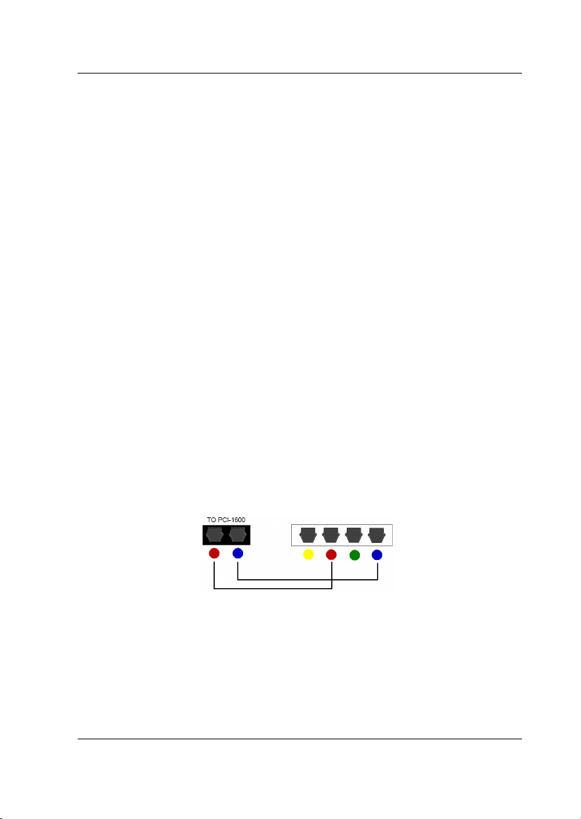
Insert the fiber optics cable into the connectors on the card you just in-
serted. Connect the other end of the cables into the connector labelled “To
PCI-1600” at the rear of the Lih 1600.
Figure 3.1: Connectors for optical cables
The Lih 1600 offers the convenience that two interfaces can be connected
to and controlled by a single PCI board in the computer. All input and
output channels of the two interfaces are fully synchronized. Consequently,
one can connect two Lih 1600 interfaces to one PCI interface card. The
new Patchmaster software automatically detects both interfaces.

8 Installation
Color coding for connecting the Lih 1600 to the LIH-1600 computer inter-
face board:
Primary interface: LIH 1600 PCI-1600
Red Red
Blue Blue
Secondary interface: LIH 1600 PCI-1600
Red Yellow
Blue Green
Now connect the power cord to the Lih 1600 and connect it to the power
line.
The Lih 1600 is now wired up, and you can proceed to the software in-
stallation as described in the following section.
http://www.heka.com

3.2 Software Installation 9
3.2 Software Installation
3.2.1 Windows NT 4.0, Windows 2000, and Win-
dows XP
In case of a Windows 2000 or Windows XP computer, the plug-and-
play system will automatically detect the PCI-1600 board and ask for
an appropriate driver. Insert the HEKA CD into the CD-ROM drive of
your computer and go to the folder “Install\ITC Drivers”. Load the file
InstruTECH.inf and then follow the instructions of the software. Finally,
you should get the message, that the driver was successfully installed.
On Windows NT computers, the new hardware is not detected automati-
cally. Please insert the HEKA CD and wait until the HEKA Installation
program comes up. Switch to the [Tools & Drivers] section and then
click on the ITC Drivers icon. Follow the instructions of the software.
If the HEKA installation program should not start automatically, run the
driver installation software (setup.exe) in the folder “Install\ITC Drivers”
from the HEKA CD.
http://www.heka.com

10 Installation
To be able to use our software (Patchmaster,Pulse,TIDA) a software
protection key (Dongle) is required. Please insert the Rainbow protection
key (labelled “SENTINEL SuperPro”) in the parallel printer port of your
computer (“LPT1” or “LPT2”). If you have a local printer connected to
your computer attach the key between the parallel port and the printer
cable. To install the protection key driver use the Dongle Driver icon in
the Tools & Drivers section of the HEKA installation program or open
the folder “Install →Rainbow” and proceed run setup.exe.
Important note: Windows does not allow you to install a
driver, if you do not have administrative rights. Make sure to
login as “Administrator” before performing any driver installa-
tion!
Now, you can install and run the acquisition software (Patchmaster,
Pulse, or TIDA).
3.2.2 Windows 98
In case of a Windows 98 computer, the plug-and-play system will auto-
matically detect the PCI-1600 board and ask for an appropriate driver.
Insert the HEKA CD into the CD-ROM drive of your computer and go
to the folder “Install\ITC Drivers”. Load the file “InstruTECH.inf” and
then follow the instructions of the software. Finally, you should get the
message, that the driver was successfully installed.
3.2.3 MacOS 9.x
Please open the “Installers” folder from the HEKA installation screen and
run the Patchmaster or Pulse installer. The driver for the hardware pro-
tection key (“dongle”) is automatically installed with the software. Patch-
master users should make sure, that the Carbon.lib on the computer is
v1.6 or higher (information on the installed Carbon.lib can be found in
the Apple System Profiler). We tested the program using CarbonLib
version 1.6, dated 16-Dec-2002. That file can be freely downloaded from
Apple’s web site.
http://www.heka.com

3.2 Software Installation 11
3.2.4 Mac OS X
On the MacOS X operating systems, drivers for the hardware pro-
tection key (“dongle”) and for the Lih 1600 need to be in-
stalled. The installer for the Lih 1600 interface can be found in
the Driver Installers/Drivers MacOSX/Installer for ITC drivers
folder. Please double-click on the installer icon to run the program.
The dongle driver is installed by copying the “Eve3.framwork” (in the
Rainbow drivers folder) into the /Library/Frameworks folder on your
computer.
Finally copy the “HEKA” folder and its content to your hard disk and
re-boot your computer.
http://www.heka.com

12 Installation
http://www.heka.com

4. Controls and Functions
4.1 Front panel controls
1. Power Indicator: The power indicator will be illuminated when
the Lih 1600 is switched on and connected to the power line.
2. Chassis Ground Connector: A 4 mm banana receptacle provides
connection to the chassis ground of the Lih 16000 interface.
3. DAC Ouputs: Four BNC connectors provide access to the four
individual 16-bit digital to analog converter outputs. The acquisition
software controls the digital to analog converter voltages and timings.
The DAC channels have an output range of ±10.24 volts. These
channels are optically isolated from the computer.
4. ADC Inputs: Eight BNC connectors provide access to the 16-bit
analog to digital converter input channels. The eight analog input
channels are separated into two banks of four. Each bank is mul-
tiplexed into one 16-bit 200 kHz A/D converter. The acquisition
software controls analog to digital converter channel selection and
sampling interval timing. The ADC channels have an input range of

14 Controls and Functions
10.24 volts. These channels are optically isolated from the computer.
Make sure that the cables that are used to connect to these chan-
nels have a very good shield, and that it is continuous to both ends
of the cable. The shield of the BNC connector must have a refer-
ence connected to it. If the BNC connector shield is left unconnected
un-expected results can occur.
Important note: Do not under any circumstances exceed
the maximum input allowed voltage of 15 volts peak.
5. Trigger Inputs: Four BNC connectors provide access to the four
fast trigger input channels. These digital input channels accept stan-
dard TTL levels (5 volts and 0 volts).
Please note: At the moment, the acquisition software supports only
the first trigger input (IN-0).
6. Trigger Outputs: Four BNC connectors provide access to four out
of the sixteen digital output channels. The acquisition software con-
trols the state of the digital output channels. These digital channels
output standard TTL levels (5 volts and 0 volts). These channels are
optically isolated from the computer.
4.2 Rear panel controls
1. Power Switch: If the power is switched on, the green LED at the
front panel should be illuminated.
2. Power Connector: Accepts standard three wire IEC female type
power cords. The appropriate power cord has been provided with
the Lih 1600. The Lih 1600 will function with a line voltage of 100
volts AC to 120 volts AC or 200 volts AC to 240 volts AC.
http://www.heka.com

4.2 Rear panel controls 15
3. Fuse: Replace fuse with 20 mm type F2A fuse only
4. Digital Out Connector: The Lih 1600 interface provides sixteen
digital output lines. Four out of the sixteen output channels are
brought out on the front panel (Out-0 to Out-3). All of the digital
channels are available on this connector. The state of the digital lines
can be set from the acquisition software.
5. Digital In Connector: The Lih 1600 interface provides sixteen
digital input lines. All of the digital channels are available on this
connector. The state of the digital lines can be read from the acqui-
sition software.
6. Computer Connector: Connection to the PCI host interface card.
The fiber optics provide superb optical isolation, virtually eliminating
ground loops, while increasing the distance between the computer and
the recording set-up to at least five meters. Fiber optic cables are
small, flexible, and, unlike conventional electrical cables do not emit
electro-magnetic radiation.
7. Telegraphing Input: Two 12-bit asynchronous “telegraphing”
ADC channels can be used for monitoring slow changing parameters.
If a so called “telegraphing” amplifier is connected to the Lih 1600,
these inputs can be used to determine the encoded amplifier gain and
filter bandwidth settings.
8. Digital I/O Connector: In this connector the digital output lines
of the Digital Out connector and the digital input lines of the
Digital In connector are brought together. This connector can be
used to control other HEKA devices, such as the Epc 8 patch clamp
amplifier or the Tib 14 trigger interface.
http://www.heka.com

16 Controls and Functions
http://www.heka.com
Table of contents
Popular Recording Equipment manuals by other brands

Mitsubishi Electric
Mitsubishi Electric DX-TL4516U series user guide

Broadcast Tools
Broadcast Tools GPI-16 Plus/RJ Installation and operation manual

Thomas Regout
Thomas Regout BalanceBox 650 installation manual

Iso-Max
Iso-Max Pro Series user guide

Oberheim
Oberheim DPX-1 owner's manual

Mitsubishi Electric
Mitsubishi Electric MAC-334IF-E installation manual

Elkron
Elkron IT3000-WIFI manual

VDH Products
VDH Products ALFANET PC-INTERFACE 2 Series Hardware user manual

Calrec
Calrec ARGO Installation & technical manual

Wheatstone Corporation
Wheatstone Corporation EMX user manual

AND
AND CC-Link Interface AD-4402-OP-20 instruction manual

Nektar
Nektar Aura Setup and user guide


