Intellijel MIDI 1U User manual

MIDI 1U System
1U USB/DIN MIDI-to-CV Interface System
Manual (English)
Revision: 2020.10.12 (PRELIMINARY)

TABLE OF CONTENTS
COMPLIANCE 3
OVERVIEW 4
INSTALLATION 5
Before You Start 5
Installing Your Modules 6
Connecting Power to the MIDI 1U 6
Connecting the MIDI 1U to a MIDI IN Jacks 1U 7
Connecting the MIDI 1U to a 7U Case 8
Connecting the MIDI 1U to a Palette Case 9
Connecting a MIDI Expander 1U 10
MIDI 1U FRONT PANEL 11
Controls 11
Outputs 12
MIDI EXPANDER 1U FRONT PANEL 14
CONFIGURING MIDI 1U USING THE FRONT PANEL 15
Learn a MIDI Channel 15
Learn the CC Jack Assignment 16
Learn the MOD Jack Assignment 17
Dual Mode 18
INTELLIJEL CONFIG APP 20
Configuring the MIDI 1U Module 21
Device Selection Column 21
MIDI 1U Config Column 22
Configuring the MIDI Expander 1U Module 24
SYSTEM RESET 25
MIDI 1U System Manual 1

COMPLIANCE
This device complies with Part 15 of the FCC Rules. Operation is subject to the
following two conditions: (1) this device may not cause harmful interference,
and (2) this device must accept any interference received, including
interference that may cause undesired operation.
Changes or modifications not expressly approved by Intellijel Designs, Inc.
could void the user’s authority to operate the equipment.
Any digital equipment has been tested and found to comply with the limits for a
Class A digital device, pursuant to part 15 of the FCC Rules. These limits are
designed to provide reasonable protection against harmful interference when
the equipment is operated in a commercial environment. This equipment
generates, uses, and can radiate radio frequency energy and, if not installed
and used in accordance with the instruction manual, may cause harmful
interference to radio communications.
This device meets the requirements of the following standards and directives:
EMC: 2014/30/EU
EN55032:2015 ; EN55103-2:2009 (EN55024) ; EN61000-3-2 ; EN61000-3-3
Low Voltage: 2014/35/EU
EN 60065:2002+A1:2006+A11:2008+A2:2010+A12:2011
RoHS2: 2011/65/EU
WEEE: 2012/19/EU
MIDI 1U System Manual 3

OVERVIEW
Intellijel’s MIDI 1U system comprises several elements, which work together to provide flexible,
programmable MIDI-to-CV conversion to your Eurorack modules: The system comprises two
mandatory components, and one optional component:
●MIDI 1U module - This 14HP 1U module receives MIDI from an attached, external MIDI input
connector (7U case, Palette case, or MIDI IN Jacks 1U module), and extracts (by default) Pitch,
Velocity, Mod, CC, Gate, Trig, Clock and Reset messages — sending the proportional voltages
to individual 3.5mm jacks for patching.
If desired, the CC and MOD jacks may be configured to respond to either Channel Aftertouch or
High Resolution CC, and the Reset jacks can be configured as a Run jack, instead.
Additionally, MIDI 1U features an alternate Dual Mode, which maintains the Clock & Reset
functionality, but uses the other six jacks to transmit Pitch, Velocity and Gate messages derived
from two separate MIDI channels.
●MIDI input connector - the MIDI 1U module does not have its own MIDI input jack. This
enables you to use the MIDI/USB inputs built-in to your Intellijel 7U Performance Case or
Palette Case. If you don’t own one of these cases, you can purchase the MIDI IN Jacks 1U
module to connect an external MIDI device.
●MIDI Expander 1U module - This optional 14HP 1U module connects to the MIDI 1U module
and adds an additional eight 3.5mm CV outputs. These outputs are fully programmable using
the Intellijel Config app, and greatly expand MIDI 1U’s ability to control your entire Eurorack
system.
NOTE: This module is not yet available. Upon its release, this manual will be updated
accordingly.
The MIDI 1U system provides all the essentials to control and sync your Eurorack modular from
your computer, mobile, or hardware MIDI device with a minimum of fuss. Several of the module’s
most important features can be changed using the two front panel buttons, with full configuration
capabilities offered via the Intellijel Config app, which is available for both Mac and Windows. The
connectivity, feature set, expandability, and compact size make the MIDI 1U system ideal for
integrating your modular gear with the rest of your rig.
MIDI 1U System Manual 4

INSTALLATION
The MIDI 1U system is designed specifically for use within an Intellijel-standard 1U row, such as
contained within the Intellijel 4U, 7U, and Palette cases. Intellijel’s 1U specification is derived from
the Eurorack mechanical specification set by Doepfer that is designed to support the use of lipped
rails within industry standard rack heights.
Power requirements for 1U conformorm to the Eurorack standard.
Before You Start
Before installing a new module in your case, you must ensure your power supply has a free power
header and sufficient available capacity to power the module:
● Sum up the specified +12V current draw for all modules, including the new one. Do the same for
the -12 V and +5V current draw. The current draw will be specified in the manufacturer's
technical specifications for each module.
● Compare each of the sums to specifications for your case’s power supply.
● Only proceed with installation if none of the values exceeds the power supply’s specifications.
Otherwise you must remove modules to free up capacity or upgrade your power supply.
You will also need to ensure your case has enough free space (hp) to fit the new module. To
prevent screws or other debris from falling into the case and shorting any electrical contacts, do not
leave gaps between adjacent modules, and cover all unused areas with blank panels. Similarly, do
not use open frames or any other enclosure that exposes the backside of any module or the power
distribution board.
You can use a tool like ModularGrid to assist in your planning. Failure to adequately power your
modules may result in damage to your modules or power supply. If you are unsure, please contact
us before proceeding.
MIDI 1U System Manual 5

Installing Your Modules
When installing or removing a module from your case always turn off the power to the case and
disconnect the power cable. Failure to do so may result in serious injury or equipment damage.
IMPORTANT: The MIDI 1U Module has two different 10-pin connectors on its circuit
board. One is for
connecting to power,
and the other is for
connecting to the
MIDI/USB jacks on
your case or MIDI IN
Jacks 1U module. Be
sure, when connecting
power, that you
connect it to the one
labelled POWER, as
indicated in the
illustration to the
right.
Connecting Power to the MIDI1U
To power the MIDI 1U module, use the included 10-pin to 16-pin cable. Plug the 10-pin end into the
10-pin connector labelled “POWER” on the MIDI 1U (as shown above). DO NOT plug it into the
other 10-pin connector. The connector is shrouded, and can only be inserted in one direction
(ensuring proper orientation if you use the supplied Intellijel power cable). If you’re using a different
power cable, make sure the red stripe (negative) is closest to the thick white line printed on the
circuit board along one edge of the POWER connector.
Plug the other end of the cable (the end with the 16-pin
connector) into the power bus board of your Eurorack case.
Ensure the red stripe on the cable lines up with the -12V
pins on the bus board. On Intellijel power supplies the pins
are labelled with “-12V” and a thick white stripe. Sometimes
the connectors are shrouded, ensuring the cable can be
oriented in only one direction. If you are using another
manufacturer’s power supply, check their documentation for
instructions.
Before reconnecting power and turning on your modular
system, double check that the ribbon cable is fully seated on
MIDI 1U System Manual 6

both ends and that all the pins are correctly aligned. If the pins are misaligned in any direction or the
ribbon is backwards you can cause damage to your module, power supply, or other modules.
After you have confirmed all the connections, you can reconnect the power cable and turn on your
modular system. You should immediately check that all your modules have powered on and are
functioning correctly. If you notice any anomalies, turn your system off immediately and check your
cabling for mistakes.
Connecting the MIDI 1U to a MIDI IN Jacks 1U
You will need to connect the MIDI 1U to either a MIDI IN Jacks 1U module or to a case with built-in
MIDI/USB jacks. This section discusses how to connect the MIDI 1U to the MIDI IN Jacks 1U
module.
1. Turn off power to the case.
2. Connect the supplied 10-pin-to-16-pin power cable between the MIDI 1U and one of the Case’s
16-pin power connectors (as discussed previously).
3. Connect one end of the supplied 10-pin to 10-pin ribbon cable to the shrouded 10-pin port on
the MIDI 1U module. The connector is keyed, and will fit in only one direction.
4. Connect the other end of the cable to the MIDI IN Jacks module.
Pay particular attention to the orientation (aligning the red wire with the white stripe on the circuit
board).
MIDI 1U System Manual 7

Connecting the MIDI 1U to a 7U Case
You will need to connect the MIDI 1U to either a MIDI IN Jacks 1U module or to a case with built-in
MIDI/USB jacks. This section shows how to connect the MIDI 1U to the MIDI/USB jacks on an
Intellijel 7U case.
1. Turn off power to the case.
2. Connect the supplied 10-pin-to-16-pin power cable between the MIDI 1U and one of the Case’s
16-pin power connectors (as discussed previously).
3. Connect one end of the supplied 10-pin to 10-pin ribbon cable to the shrouded 10-pin port on
the MIDI 1U module. The connector is keyed, and will fit in only one direction.
4. Connect the other end of the cable to the MIDI Jacks circuit board on your 7U case. On newer
7U cases, this connector is shrouded (ensuring the cable fits in only one orientation). On older
cases, the connector is not shrouded, so pay particular attention to the orientation (aligning the
red wire with the white stripe on the circuit board).
5. Power on the 7U Case.
The MIDI 1U module will now receive MIDI from the 7U case’s MIDI IN jacks (both USB and
5-pin MIDI) and convert it to CV. In addition, the 7U case’s MIDI OUT jack will function as a
MIDI Thru — passing along any MIDI data received at its MIDI IN jack.
MIDI 1U System Manual 8

Connecting the MIDI 1U to a Palette Case
You will need to connect the MIDI 1U to either a MIDI IN Jacks 1U module or to a case with built-in
MIDI/USB jacks. This section discusses how to connect the MIDI 1U to the MIDI/USB jacks on an
Intellijel Palette case.
1. Turn off power to the Palette Case.
2. Connect the supplied 10-pin-to-16-pin power cable between the MIDI 1U and one your case’s
16-pin power connectors (as discussed previously).
IMPORTANT: Be sure to plug power into the MIDI 1U’s POWER connector, and not the
other 10-pin connector, as illustrated earlier in Installing Your Modules .
3. Connect one end of the supplied 10-pin to 10-pin ribbon cable to the shrouded 10-pin port on
the MIDI 1U module. The connector is keyed, and will fit in only one direction.
4. Connect the other end of the supplied 10-pin-to-10-pin ribbon cable to the shrouded 10-pin port
on the Palette Circuit Board. The connector is keyed, and will fit in only one direction.
The example on the right
illustrates the connection to the
circuit board on a Palette 62
case.
The example below illustrates
the connection to the circuit
board on a Palette 104 case.
5. Power on the Palette Case.
The MIDI 1U module will now receive MIDI from the Palette’s MIDI IN jacks (both USB and
Type-A TRS-MIDI) and convert it to CV. In addition, the Palette’s MIDI OUT jack will function as
a MIDI Thru — passing along any MIDI data received at its MIDI IN jack.
MIDI 1U System Manual 9

Connecting a MIDI Expander 1U
NOTE: The MIDI Expander 1U Module is not yet available. Once it is, these instructions will
be updated accordingly.
If you use the optional MIDI Expander 1U module, you will need to connect it to both power and to
the MIDI 1U module.
1. Turn off power to your case.
2. Connect the supplied 10-pin-to-16-pin power cable between the MIDI Expander 1U and one of
your case’ 16-pin power connectors (as discussed earlier in Connecting Power to the MIDI 1U ).
3. Connect one end of the supplied 6-pin to 6-pin ribbon cable to the 6-pin connector on the
MIDI 1U module. The connector is keyed, and will fit in only one direction.
4. Connect the other end of the supplied 6-pin-to-6-pin ribbon cable to the 6-pin connector on the
MIDI Expander 1U. The connector is keyed, and will fit in only one direction.
5. Power on the Case.
MIDI 1U System Manual 10

MIDI 1U FRONT PANEL
Controls
[1] CLK ÷ button - This button serves two
functions.
NORMAL OPERATION:
In normal operation (i.e., the
LEARN [2] button is off/unlit),
pressing CLK ÷ sets the clock division
of the incoming MIDI clock. Press the
CLK ÷ button repeatedly to cycle
through the following divisions of 96:
● /1 (clock out = 24 ppq)
● /3 (clock out = 32nd notes)
● /6 (clock out = 16th notes)
● /12 (clock out = eighth notes)
● /24 (clock out = quarter notes)
● /48 (clock out = half notes)
● /96 (clock out = whole notes)
The CLK LED blinks in time with the clock division.
Alternatively, you can use the Intellijel Config app to set the desired Clock Division.
LEARN OPERATION:
When the MIDI 1U is in either LEARN CC+CH mode ( solid blue LEARN button) or in
LEARN MOD+CH ( flashing blue LEARN button), then the CLK ÷ button lights either solid
green , or it flashes red / green . Pressing the CLK ÷ button toggles between the two, and is
used to assign a polarity while learning the CC [G] or MOD [D] assignment.
GREEN : If the CLK ÷ button is solid green when learning a CC or MOD assignment,
then the CC or MOD voltage will be unipolar (i.e. CC Values of 0-127 = 0V - 5V).
RED / GREEN : If the CLK ÷ button is flashing red / green when learning a CC or MOD
assignment, then the CC or MOD voltage will be bipolar (i.e. CC Value of 64 = 0V;
CC Value of 0 = -5V; CC Value of 127 = +5V).
Alternatively, you can use the Intellijel Config app to set the CC or MOD polarity.
NOTE: MIDI 1U automatically saves any changes after 2 seconds of MIDI inactivity — ensuring
it returns to exactly the same state after a power cycle, and that it does not interfere with
time-sensitive operations (such as clock). The buttons flash green when MIDI 1U auto-saves its
settings.
MIDI 1U System Manual 11

[2] LEARN button - Use this button to learn
which MIDI channel the MIDI 1U will
respond to, as well as the MIDI CC
numbers assigned to both the CC [G] and
MOD [D] output jacks.
MIDI 1U automatically saves all learned
settings (both buttons flash green ) after
2 seconds of MIDI inactivity, ensuring it
returns to exactly the same state after a
power cycle.
Pressing the button cycles through three states:
OFF : When the LEARN button is off, MIDI 1U is in normal operation and works to convert
incoming MIDI data into CV for your eurorack system.
SOLID BLUE : Indicates the MIDI 1U is in LEARN CC+CH mode , meaning the module is
awaiting a MIDI message, and that it will use the first message it receives to set both the
module’s MIDI Receive channel and CC [G] jack assignment. In addition, it will set the
CC jack’s polarity based on the status of the CLK ÷ button, as discussed earlier.
FLASHING BLUE : Indicates the MIDI 1U is in LEARN MOD+CH mode , meaning the
module is awaiting a MIDI message, and that it will use the first message it receives to set
both the module’s MIDI Receive channel and MOD [D] jack assignment. In addition, it will
set the MOD jack’s polarity based on the status of the CLK ÷ button, as discussed earlier.
For more information about using the LEARN button, see Configuring MIDI 1U Using the Front
Panel , later in this manual.
Alternatively, you can set the MIDI channel, MOD and CC jack assignments using the Intellijel
Config app, discussed later.
DUAL MODE: MIDI 1U offers an alternate, dual channel mode that reconfigures the jacks for
2-channel operation. In this mode, you have independent MIDI control of the pitch, gate and
velocity for two different MIDI channels. See Dual Mode for detailed information about enabling
the mode, and using the LEARN button within it.
Outputs
[A] CLK out - Clock output, which transmits a divided MIDI clock pulse with a division set by the
CLK ± [1] button. The corresponding LED blinks in time with the CLK out.
Alternatively, you can use the Intellijel Config app to set the desired Clock Division.
[B] RST out - Operates as either a RESET output or a RUN output, depending on how it’s
configured inthe Intellijel Config app.
MIDI 1U System Manual 12

If configured as a RESET output (the factory default), this jack transmits a trigger signal
whenever a MIDI reset message is received. The corresponding LED lights whenever a RESET
message is sent.
If configured as a RUN output, this jack
transmits a run gate that stays high (5V)
for as long as the external MIDI clock in is
running. Stopping the external MIDI clock
sets the gate low (0V). This is useful for
starting/stopping any eurorack sequences
in sync with an external MIDI sequencer.
The corresponding LED lights whenever
the RUN gate is high.
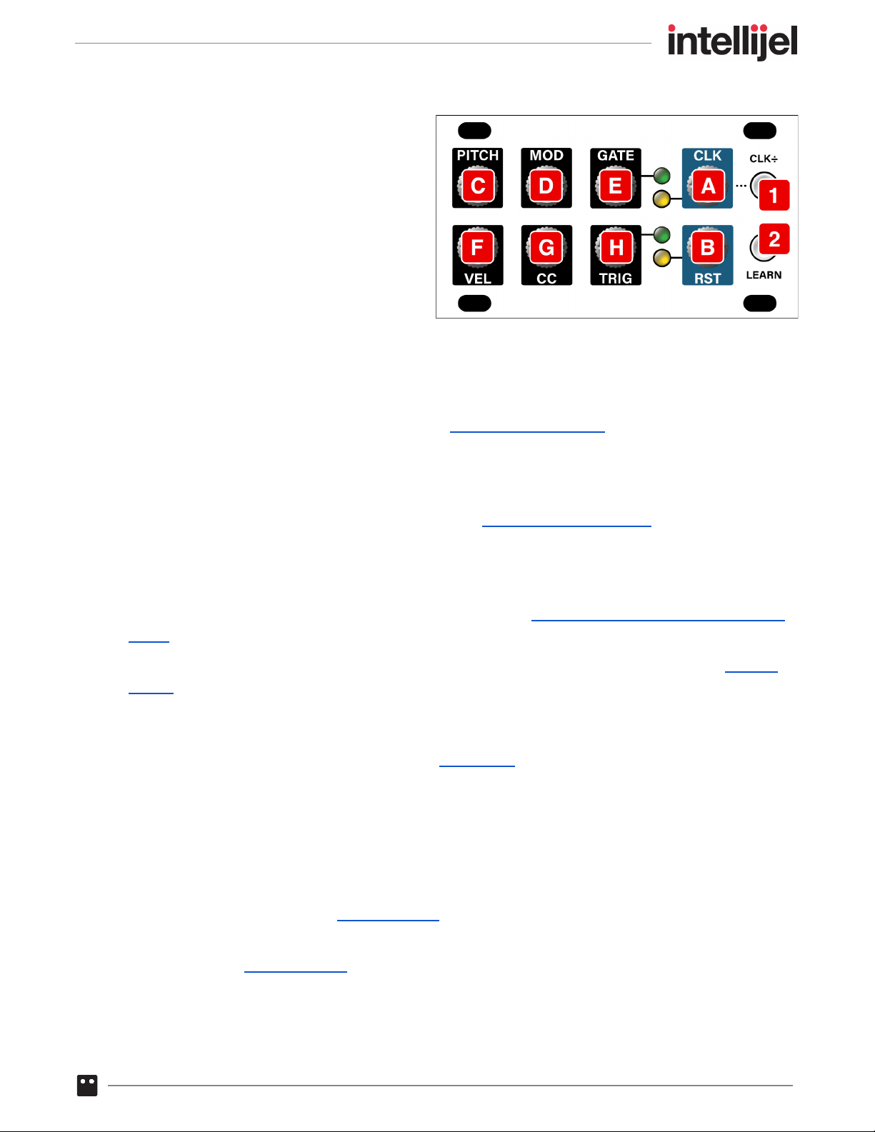
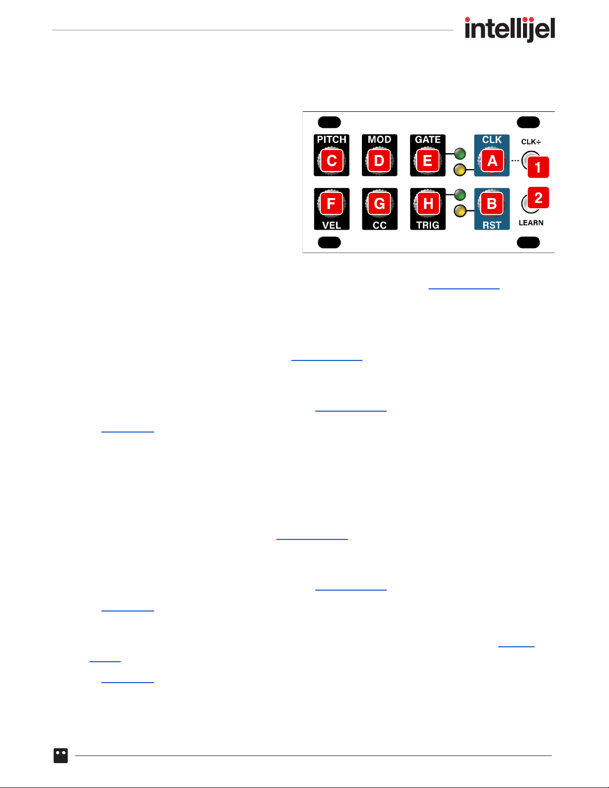
[C] PITCH out - 1V/oct CV output with a range of ±5V. The voltage output is determined by the pitch
of the MIDI input’s last played note and its pitch bend control. Use the Intellijel Config app to
configure various pitch-related parameters, such as Pitch Bend Range, and Coarse Tuning.
MIDI note 0 (C-2) maps to -5V and note 120 (C8) maps to +5V.
[D] MOD out - CV output with a range of either 0-5V or ±5V (depending on the polarity assignment,
as set either with CLK ± [1] button or the Intellijel Config app).
By default, this jack outputs a control voltage proportional to the Mod Wheel data (CC #1)
transmitted by your MIDI controller. You can override this default using the LEARN [2] button, or
you can redefine its purpose entirely using the Intellijel Config app.
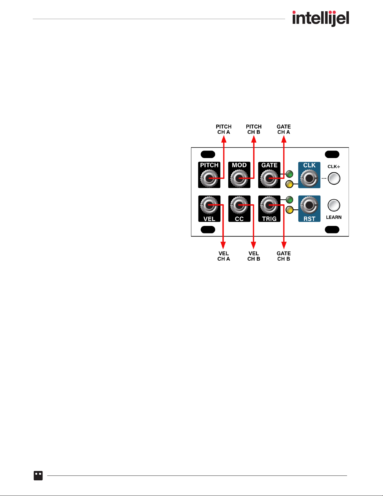
In Dual Mode , this jack outputs CH B’s PITCH signal.
[E] GATE out - Gate output, which is high (5V) for as long as a note is being held. The
corresponding LED lights whenever the GATE out is high.
[F] VEL out - CV output with a range of 0 - 5V. The voltage is proportional to the velocity of the MIDI
input’s last played note.
[G] CC out - CV output with a range of either 0-5V or ±5V (depending on the polarity assignment, as
set either with CLK ± [1] button or the Intellijel Config app).
By default, this outputs a control voltage proportional to the Breath Controller data (CC #2),
transmitted by your MIDI controller. You can override this default using the LEARN [2] button, or
you can redefine its purpose entirely using the Intellijel Config app.
In Dual Mode , this jack outputs CH B’s VELOCITY signal.
[H] TRIG out - Trigger output, which transmits a trigger signal whenever a MIDI Note On message
is received. By default, the Trigger length is 5ms, but you can override this using the Intellijel
Config app. The corresponding LED lights whenever the TRIGGER out is high.
In Dual Mode , this jack outputs CH B’s GATE signal.
MIDI 1U System Manual 13

MIDI EXPANDER 1U FRONT PANEL
This module is not yet available. The
manual will be updated and completed
when it is.
The optional MIDI expander has
eight user-assignable outputs. Using the
Intellijel Config app, you can assign each of
the eight jacks to generate just about any
type of voltage that can be derived from a
MIDI signal.
MIDI 1U System Manual 14

CONFIGURING MIDI 1U USING THE FRONT PANEL
You can configure the MIDI 1U module using either its front panel or the Intellijel Config app
(available for download from www.intellijel.com). This section discusses configuration via the front
panel. Using the Intellijel Config app is discussed later in this manual.
Much of MIDI 1U can be configured via the LEARN and CLK ÷ buttons on its front panel, as
outlined here:
Learn a MIDI Channel
You can set the MIDI 1U’s MIDI receive channel using its LEARN button. Specifically:
1. If the LEARN [2] button is not lit, press it once to enter LEARN CC+CH mode.
In LEARN CC+CH mode , the LEARN button lights solid blue , indicating the MIDI 1U is awaiting
a MIDI message (and that it’s also capable of learning the CC jack assignment).
You can also learn a MIDI Channel if you press the LEARN button twice , which enters
LEARN MOD+CH mode . In LEARN MOD+CH mode, the LEARN button flashes blue , indicating
that MIDI 1U is awaiting a MIDI message (and that it’s also capable of learning the MOD jack
assignment).
2. Send any channel-based MIDI message into the MIDI 1U.
MIDI 1U will automatically sets itself to the sent message’s MIDI channel, and the LEARN
button will extinguish.
Additionally, MIDI 1U will automatically save all learned settings (both buttons flash green ) after
2 seconds of MIDI inactivity, ensuring it returns to exactly the same state after a power cycle.
MIDI 1U System Manual 15

Learn the CC Jack Assignment
You can assign a function to the MIDI 1U’s CC [G] jack using the LEARN button. Specifically:
1. If the LEARN [2] button is not lit, press it once to enter LEARN CC+CH mode.
In LEARN CC+CH mode, the LEARN button lights solid blue , indicating the MIDI 1U is awaiting
a MIDI message (and that it’s capable of learning both the MIDI channel and the CC jack
assignment).
NOTE: If you press the LEARN button twice, it will flash to indicate you’re in LEARN MOD+CH
mode, which learns the MOD [D] jack assignment, rather than the CC jack, as described later .
2. Press the CLK ÷ [1] button to toggle between having it light solid green or having it
flash red / green .
GREEN : If the CLK ÷ button is solid green when learning the CC jack assignment, then the
MOD voltage will be unipolar (i.e. CC Values of 0-127 = 0V - 5V).
RED / GREEN : If the CLK ÷ button is flashing red / green when learning the CC jack
assignment, then the MOD voltage will be bipolar (i.e. CC Value of 64 = 0V; CC Value of 0 =
-5V; CC Value of 127 = +5V).
3. Send the MIDI 1U a MIDI message using the MIDI CC number that you want assigned to the
MIDI 1U’s CC [G] jack.
MIDI 1U will automatically assign its CC jack to the CC# sent (also setting its MIDI channel to
match); assign the desired polarity to that jack; and extinguish the LEARN button.
For example, if you turn an Expression (CC 11) knob on a MIDI controller assigned to
Channel 2, then MIDI 1U will automatically assign itself to respond to CH 2, and it will configure
its CC out jack to transmit a control voltage based on Expression (CC 11) data from your MIDI
source.
Additionally, MIDI 1U will automatically save all learned settings after 2 seconds of MIDI activity
(both buttons flash green ), ensuring it returns to exactly the same state after a power cycle.
MIDI 1U System Manual 16

Learn the MOD Jack Assignment
You can assign a function to the MIDI 1U’s MOD [D] jack using the LEARN button. Specifically:
1. If the LEARN [2] button is not lit, press it twice to enter LEARN CC+CH mode.
In LEARN MOD+CH mode, the LEARN button flashes blue , indicating the MIDI 1U is awaiting
a MIDI message (and that it’s capable of learning both the MIDI channel and the MOD jack
assignment).
NOTE: If you press the LEARN button only once, it will light solid blue to indicate you’re in
LEARN CC+CH mode, which learns the CC [G] jack assignment, rather than the MOD jack, as
described previously .
2. Press the CLK ÷ [1] button to toggle between having it light solid green or having it
flash red / green .
GREEN : If the CLK ÷ button is solid green when learning the MOD jack assignment, then
the MOD voltage will be unipolar (i.e. CC Values of 0-127 = 0V - 5V).
RED / GREEN : If the CLK ÷ button is flashing red / green when learning the MOD jack
assignment, then the MOD voltage will be bipolar (i.e. CC Value of 64 = 0V; CC Value of 0 =
-5V; CC Value of 127 = +5V).
3. Send the MIDI 1U a MIDI message using the MIDI CC number that you want assigned to the
MIDI 1U’s MOD [D] jack.
MIDI 1U will automatically assign its MOD jack to the CC# sent (also setting its MIDI channel to
match); assign the desired polarity to that jack, and extinguish the LEARN button.
For example, if you turn a Portamento Time (CC 5) knob on a MIDI controller assigned to
Channel 3, then MIDI 1U will automatically assign itself to respond to CH 3, and it will configure
its MOD jack to transmit a control voltage based on Portamento Time (CC 5) data from your
MIDI source.
Additionally, MIDI 1U will automatically save all learned settings (both buttons flash green ) after
2 seconds of MIDI activity, ensuring it returns to exactly the same state after a power cycle.
MIDI 1U System Manual 17

Dual Mode
MIDI 1U offers an alternate, dual channel mode that reconfigures the jacks for 2-channel operation.
In this mode, you have independent MIDI control of the pitch, gate and velocity for two different
MIDI channels (repurposing the MOD , CC and TRIG jacks for PITCH , VEL and GATE jacks,
respectively, for CH B). Also, you will need to configure any desired CLK division before entering
Dual Mode.
To enter Dual Mode:
1. Long press (>1.5 sec) the LEARN button.
MIDI 1U reconfigures as a dual channel
device, and the jacks take on the
functions indicated in the graphic to the
right.
Both the CLK ÷ and LEARN buttons glow
yellow , indicating the device is in Dual
Mode.
To Learn MIDI Channels:
1. Press the LEARN button to prepare for
learning CH A.
The LEARN button will turn red , and the
CLK ÷ button will extinguish.
2. Send any channel-based MIDI message into the MIDI 1U.
CH A automatically sets itself to the sent message’s MIDI channel.
NOTE: By default, CH A is set to the same MIDI channel used by Normal Mode. So, if you’re
happy with that selection, you don’t need to learn CH A’s channel, and can proceed to learning
CH B, as described below.
3. Press the LEARN button again to prepare for learning the CH B.
The LEARN button will flash red , and the CLK ÷ button will remain off.
4. Send any channel-based MIDI message into the MIDI 1U.
CH B automatically sets itself to the sent message’s MIDI channel, and the LEARN button will
stop flashing, and the unit will return to Dual Mode (both buttons lit yellow ).
NOTE: MIDI 1U will automatically save any new configuration after 2 seconds of MIDI activity
(both buttons flash green ), ensuring it returns to exactly the same state after a power cycle.
MIDI 1U System Manual 18

To exit Dual Mode:
1. If MIDI 1U is currently in Dual Mode (both button LEDs lit yellow ), long press (>1.5 sec) the
LEARN button to revert to Normal Mode.
MIDI 1U reconfigures back to a single channel device, and restores the MOD , CC and TRIG
settings to their previously programmed conditions.
NOTE: By default, Normal Mode uses the same MIDI channel as CH A. So, if you changed
CH A’s setting in Dual Mode, that will be the new MIDI channel assignment in Normal Mode.
MIDI 1U System Manual 19
Table of contents
Other Intellijel Recording Equipment manuals

Intellijel
Intellijel Quadrax User manual

Intellijel
Intellijel Passive LPG 1U User manual

Intellijel
Intellijel Shifty User manual

Intellijel
Intellijel Steppy 3U User manual

Intellijel
Intellijel MIDI1U User manual

Intellijel
Intellijel Planar2 User manual

Intellijel
Intellijel Audio I/O v3 2023 User manual

Intellijel
Intellijel Tangrams User manual

Intellijel
Intellijel Palette 104 User manual

Intellijel
Intellijel XFADE 1U User manual