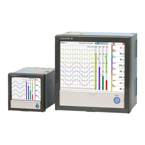
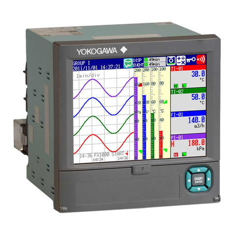
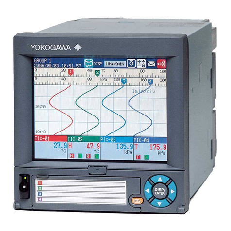
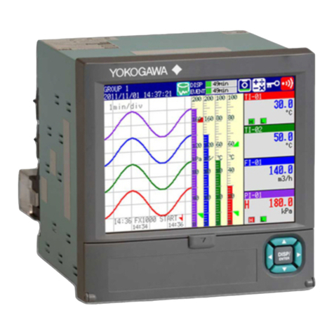
YOKOGAWA DXAdvancedR4 DX1000 User manual

User’s
Manual
Yokogawa Electric Corporation
DX1000/DX1000N/DX2000
PROFIBUS-DP (/CP1)
Communication Interface
IM 04L41B01-19E
4th Edition


1
IM 04L41B01-19E
Thank you for purchasing Daqstation DX1000, DX1000N, or DX2000 (Hereafter, called
"DX").
This manual explains the PROFIBUS-DP (/CP1 option) communication function of the DX.
Read this manual together with other User's Manuals (IM04L41B01-01E, IM04L42B01-01E,
and IM04L41B01-17E).
Notes
● Thecontentofthismanualmaychangewithoutpriornoticeinviewofimprovingthe
performance and function.
● Weensurethecontentofthismanual.If,however,thereareanymistakesorquestionable
points,contactourbranchoffice,branchstore,orbusinessoffice.
● Reprinting or reproduction of all or parts of the content of this manual is prohibited
without permission.
● WedevelopedandcreatedtheTCP/IPsoftwareandTCP/IPsoftwaredocumentsofthis
productbasedonBSDNetworkingSoftwareRelease1licensedfromtheUniversityof
California.
QR Code
The product has a QR Code pasted for efficient plant maintenance work and asset
information management.
Itenablesconfirmingthespecificationsofpurchasedproductsanduser’smanuals.
For more details, please refer to the following URL.
https://www.yokogawa.com/qr-code
QRCodeisaregisteredtrademarkofDENSOWAVEINCORPORATED.
Trademarks
● DAQSTATION,Daqstation,andDXAdvancedareourregisteredtrademarks.
● Microsoft and Windows are the registered trademarks or trademarks of Microsoft
Corporation in the United States and other countries.
● Adobe andAcrobat are the registered trademarks or trademarks ofAdobe Systems
Incorporated.
● KerberosisatrademarkoftheMassachusettsInstituteofTechnology(MIT).
● Otherproductandcompanynamesdescribedinthismanualareregistered
trademarksortrademarksoftheirrespectivecompanies.
● Thismanualdoesnotdisplaymarks ®and ™fortheregistered trademarksor
trademarks of each company.
Revisions
November2008: 1stEdition
March2010: 2ndEdition
December2010: 3rdEdition
June2020: 4thEdition
4thEditionJune2020(YK)
AllRightsReserved,Copyright©2008,YokogawaElectricCorporation
2IM 04L41B01-19E
Symbols Used in This Manual
●Units
• k:Denotes1000.Examples:5kg,100kHz
• K:Denotes1024.Example:640Kbytes
● Cautionarynotes
InthisUser'sManual,cautionarynotesaredistinguishedbythefollowingsymbols:
Refer to corresponding location on the instrument. This symbol
appears on dangerous locations on the instrument which require
special instructions for proper handling or use. The same symbol
appears in the corresponding place in the manual to identify those
instructions.
WARNING
Calls attention to actions or conditions that could cause serious
injury or death to the user, and precautions that can be taken to
prevent such occurrences.
CAUTION Calls attentions to actions or conditions that could cause light
injury to the user or damage to the instrument or user’s data, and
precautions that can be taken to prevent such occurrences.
Note
Calls attention to information that is important for proper operation of
the instrumen
● Boldcharacters
Denotes key or character string that appear on the DX screen.
Thesymbol indicates the key operation and menu selection procedure on the DX.

3
IM 04L41B01-19E
Assumption of Explanation
TheexplanationinthismanualassumesthattheDXisconnectedviacommunications
with ProgrammableLogicController(PLC).ForinformationonhowtooperatePLCs,see
theuser'smanualofrespectiveproducts.
ThismanualisintendedforthosewhohaveusedanPROFIBUS-DP.
In this manual, the screens of the DX1000 are used. The content displayed on the DX2000
screens are not different from those displayed on the DX1000 screen.
Revision History
Edition DX Description
1Releasenumber3
(Version3.0x)
Newlypublished.
Stylenumber3
2Releasenumber4
(Version4.0x)
Additionsandimprovementstoexplanations.
Stylenumber3
3Same as edition 2. Fixed explanations.
4Releasenumber4
(Version4.2x)
Changed the EtherNet/IP name.
Stylenumber5

4IM 04L41B01-19E
Contents
SymbolsUsedinThisManual ...................................................................................................................2
AssumptionofExplanation ........................................................................................................................ 3
RevisionHistory.........................................................................................................................................3
Introduction of Features ......................................................................................................................5
PROFIBUS-DP ..........................................................................................................................................5
WhattheDXCanDo ................................................................................................................................. 6
Settings of the DX......................................................................................................................................6
AccesstotheDX .......................................................................................................................................6
Connection to the PROFIBUS-DP Network ........................................................................................7
CableConnection ......................................................................................................................................7
Settings of the DX......................................................................................................................................8
Others ........................................................................................................................................................8
Preparation for PLC ............................................................................................................................9
GSD File ....................................................................................................................................................9
SpecicationofData................................................................................................................................10
Communication Connection..................................................................................................................... 10
I/OBuerandDataMapping ............................................................................................................11
MappingMethodoftheI/Obuer ............................................................................................................ 11
Data Count and Data Type ...................................................................................................................... 11
Data Mapping ..........................................................................................................................................12
Specications ....................................................................................................................................23
BasicSpecications.................................................................................................................................23
Index .................................................................................................................................................24

5
IM 04L41B01-19E
Introduction of Features
PROFIBUS-DP
PROFIBUS is an open field bus standard (IEC61158) used in various applications for
factory automation and process automation.
PROFIBUS-DP(DecentralizedPeriphery)isusedforcommunicationbetweenPLCsand
remoteI/O,enablinghigh-speeddatatransmission.
Configuration Components
PROFIBUS-DPnetworkconsistsoffollowingcomponents:
• Class 1 master
Acontrollertoexchangeinformationwiththeslaveinacyclicmanner.ThisisaPLCor
PC.
• Class 2 master
Engineering and configuration devices.This is either a PC on which configuration
softwarehasbeeninstalledorsoftwareitself.
• Slave
I/Odevicesaccessedbythemaster.ThisincludesI/Odevices,sensors,oractuaters.
TheDXisaslavedevice.
• Terminator
Theterminatorofthebus.
• Cable
Adedicatedtwo-wirecableisused.
• Others
Repeater, coupler, and other components are also used if needed.
Node
127nodescanbeconnectedtothenetwork.
Note
FordetailsofPROFIBUSspecificationsandinformation,seethedocumentspublishedfromthe
PROFIBUSOrganizationinrespectiveregions.
PROFIBUS-DP
Slave Slave Slave
PROFIBU-DP Master (Class 1)
PLC etc.
PROFIBU-DP Master (Class 2)
PC
Terminator Terminator
Cable

6IM 04L41B01-19E
What the DX Can Do
TheDXprovidesthefollowingfunctions:
• ParticipateinanPROFIBUS-DPnetworkasaPROFIBUS-DPslave.
• Communicate with a PLC from Siemens.
• The master can access internal data of the DX.
Data Access
Measurement channel data Read
Computation channel*1 data Read
Communication input data*1*2 Write
*1 This is an option (/M1 and /PM1).
*2 Communication input data, if coded in a calculation expression in the computation channel,
canbedisplayedontheDX.
The following shows examples of usage.
• DataondevicesonanetworkcanberecordedbyaPLCtotheDX.
• DatameasuredbytheDXcanbeacquiredbyaPLC.
Settings of the DX
TheDXisreadytouseafterthenodeaddresssettingshavebeenmade.
Access to the DX
TheDXisapassivedeviceonanPROFIBUS-DP.TheDXcannotinitiatearequest.PLC,
aclass1masterdevice,initiatesarequestandaccessestheDX.
Introduction of Features

7
IM 04L41B01-19E
Connection to the PROFIBUS-DP Network
Cable Connection
ConnectthePROFIBUS-DPcabletoaPROFIBUS-DPconnectorprovidedontheback
of the DX.
5 4 3 2 1
9 8 7 6
(Rear panel)
Connector
D-sub9-pin(female)connector.Eachpincorrespondstothefollowingsignals.
Pin Signal name Explanation
3 RxD/TxD - P Positivedatareceive/transmit.
4 CNTR - P RTS(forusebyrepeater).
5 DGND Ground.
6 VP+5V +5V.
8 RxD/TxD - N Negativedatareceive/transmit.
Pins 1, 2, 7, and 9 are not used.
Cable
Adedicatedtwo-wirecableisused(twowiresforthesignal).Thisisnotsuppliedwiththe
DX.Tobepreparedseparately.
Transmission Rate/Transmission Distance
Thetransmissionratevariesdependingonthetransmissiondistancewithinthefollowing
range.
9.6Kbps/1200mto12Mbps/100m
Terminator
TheDXhasnobuilt-interminatorcircuit.Ifaterminatorisneededintermsofwiring,use
a connector with a terminator.

8IM 04L41B01-19E
Settings of the DX
Node Address Settings
Press MENU (to switch to setting mode), hold down FUNCfor3s(toswitchtobasic
setting mode), and select the Menutab> Communication (PROFIBUS).
• Node Address
Setanodeaddressintherangeof0to125.
Note
ThenodeaddressofPROFIBUS-DPcanbecheckedontheNetworkInformationScreenofthe
DX.YoucanopentheNetworkInformationScreenbypressingFUNC>Network info softkey.
Others
Status Output (option, /F1 and /F2)
If setting Communication error of the Status Output (/F1 or /F2 option) to On, a relay
outputisprovidedwhenaPROFIBUS-DPcommunicationerroroccurswithintheDX.If
acommunicationerroroccurs,contactyournearestYOKOGAWAdealerforrepairs.
See Section 2.9 of the DX1000/DX1000N User's Manual (IM04L41B01-01E) or DX2000
User's Manual (IM04142B01-01E).
In Basic Setting Mode:
WhentheDXisinthebasicsettingmode,communicationsareavailablebutinput/output
dataisinvalid.
Connection to the PROFIBUS-DP Network

9
IM 04L41B01-19E
Preparation for PLC
GSD File
Installation
To have theDX participate in anetwork, you must first install the DX device database
file (GSD file) in the configurationtool.APLCcommunicateswiththeDXbasedonthe
information in the GSD file.
For information on using the configuration tool, see the configuration tool user's manual.
PROFIBU-DP
GSD file
PROFIBUS configuration tool
DX
PLC
How to Obtain the GSD File
ObtaintheGSDfilefromtheYokogawaWebsite:
URL:www.yokogawa.com/ns/dxadv/download/
Contents of the GSD File
Contentsotherthanthoselistedinthefollowingtableareomitted.
Item Description
Model Name DataAcquisitionPROFIBUSI/F
SlaveFamily 0

10 IM 04L41B01-19E
Specification of Data
If you install the GSD file, the DX is added to the configuration tool as a "General" type
"Slave".Select[Model]toexpandthemodulelistandselectyourDXmodelfromthelist.
Item Explanation
Model ThemodelnamedescribedintheGSDfile.Selectthedeviceto
beconfiguredfromthemodelnameofthe"General"typeand
the"Slave"inthedevicestreeorlistbox.
DataAcquisitionPROFIBUSI/F
Module The DX models are referred to as modules. Selecting the
model"DataAcquisitionPROFIBUSI/F"allowsyoutoselecta
module.
DX1002 DX1002, DX1002N, without Option/M1 and /PM1
DX1002/M1 DX1002, DX1002N, with Option/M1 or /PM1
DX1004 DX1004, DX1004N, without Option/M1 and /PM1
DX1004/M1 DX1004, DX1004N, with Option/M1 or /PM1
DX1006 DX1006,DX1006N,withoutOption/M1and/PM1
DX1006/M1 DX1006,DX1006N,withOption/M1or/PM1
DX1012 DX1012, DX1012N, without Option/M1 and /PM1
DX1012/M1 DX1012, DX1012N, with Option/M1 or /PM1
DX2004 DX2004, without Option/M1 and /PM1
DX2004/M1 DX2004, with Option/M1 or /PM1
DX2008 DX2008,withoutOption/M1and/PM1
DX2008/M1 DX2008,withOption/M1or/PM1
DX2010 DX2010, without Option/M1 and /PM1
DX2010/M1 DX2010, with Option/M1 or /PM1
DX2020 DX2020, without Option/M1 and /PM1
DX2020/M1 DX2020, with Option/M1 or /PM1
DX2030 DX2030,withoutOption/M1and/PM1
DX2030/M1 DX2030,withOption/M1or/PM1
DX2040 DX2040, without Option/M1 and /PM1
DX2040/M1 DX2040, with Option/M1 or /PM1
DX2048 DX2048,withoutOption/M1and/PM1
DX2048/M1 DX2048,withOption/M1or/PM1
Communication Connection
You can establish a communication connection by using the configuraton tool and run
it with a PLC. For information on using the configuration tool and a PLC, see the user's
manuals of these products.
Preparation for PLC

11
IM 04L41B01-19E
I/O Buffer and Data Mapping
AmasterdevicesuchasaPLCaccessesinternaldataofthe DXviathe "Inputbuffer"
and"Outputbuffer"oftheDX."Input"representsaninputtothemaster,while"Output"
represents an output from the master.
Mapping Method of the I/O buffer
The "Inputbuffer"and"Outputbuffer"oftheDXforPROFIBUS-DPcommunicationhas
128byteseach.Dataislaidoutasdescribedinthefollowingtable.Datalayoutcannot
bechanged.
Buffer Application Description
Input Reading
measurement channel
data and computation
channel data
Locates all the measurement channel data from the top of
thebuffer.Locatesasmuchcomputationchanneldataas
possibleintheremainingpartofthebuffer.
Buffer Application Description
Output Writing
communication input
data
Locatesasmuchcommunicationinputdataaspossible.
Data Count and Data Type
TheDXdatacountisasfollows:
Model Measurement channel Computation channel Communication input
data
Count Number Count Number Count Number
DX1002 2 001, 002 12 101 to 112 24 C01 to C24
DX1004 4 001 to 004
DX1006 6 001to006 24 101 to 124
DX1012 12 001 to 012
DX2004 4 001 to 004 12 101 to 112 60 C01toC32
(C33toC60)*1
DX2008 8 001to008
DX2010 10 001 to 010 60 101 to 127
(128to160)*1
DX2020 20 001 to 020 101 to 122
(123to160)*1
DX2030 30 001to030 101 to 117
(118to160)*1
DX2040 40 001 to 040 101 to 112
(113to160)*1
DX2048 48 001to048 101to108
(109to160)*1
*1DatainparenthesescannotbelocatedinabufferbecauseitexceedsthecapacityoftheI/O
buffer.
Note
The communication input data for C01 to C24 (on the DX1000) or for C01 to C32 (on the
DX2000)isreservedforPROFIBUS-DP.
Youcannotwritetothesedatanumbersthroughothermeans(suchasModbus,PLC
communication protocol, or communication commands).

12 IM 04L41B01-19E
Data Mapping
Datamappingforeachmodelisshowninthetable.Thefollowingsymbolsareusedin
thetable.
Symbol Explanation
CH1, CH2 Data of the measurement channel 1 or measurement channel 2.
CH101, CH112 Data of the computation channel 101 or computation channel 112.
C01, C24 Communication input data.
INT16 16-bitsignedinteger.
INT32_B 32-bitsignedinteger,BigEndian*.
*BigEndian:Assumingthatavalueof01020304Hislocatedas01020304inthebuffer.
Note
• Toacquireaphysicalvalueofthemeasurementchanneldataorcomputationchanneldata,
itisnecessarytoobtainthedecimal place and unitinformationinadvance.
• ThechanneldataorcommunicationinputdatathatcannotbeallocatedintheI/Obufferis
not supported..
DX1002
Mappingoftheinputbuffer
Offset Description Data type
0 – 1 CH1 INT16
2–3 CH2
4 – 7 CH101 INT32_B
8–11 CH102
12–15 CH103
16–19 CH104
20–23 CH105
24 – 27 CH106
28–31 CH107
32–35 CH108
36–39 CH109
40–43 CH110
44 – 47 CH111
48–51 CH112
52–127 Always0. -
I/O Buffer and Data Mapping

13
IM 04L41B01-19E
Mappingoftheoutputbuffer
Offset Description Data type
0–3 C01 INT32_B
4 – 7 C02
8–11 C03
12–15 C04
16–19 C05
20–23 C06
24 – 27 C07
28–31 C08
32–35 C09
36–39 C10
40–43 C11
44 – 47 C12
48–51 C13
52–55 C14
56–59 C15
60–63 C16
64–67 C17
68–71 C18
72–75 C19
76–79 C20
80–83 C21
84–87 C22
88–91 C23
92–95 C24
96–127 Ignore anything that is written. -
DX1004
Mappingoftheinputbuffer
Offset Description Data type
0 – 1 CH1 INT16
2–3 CH2
4–5 CH3
6–7 CH4
8–11 CH101 INT32_B
12–15 CH102
16–19 CH103
20–23 CH104
24 – 27 CH105
28–31 CH106
32–35 CH107
36–39 CH108
40–43 CH109
44 – 47 CH110
48–51 CH111
52–55 CH112
56–127 Always0. -
Mappingoftheoutputbuffer
SameasforthemappingoftheDX1002outputbuffer.
I/O Buffer and Data Mapping

14 IM 04L41B01-19E
DX1006
Mappingoftheinputbuffer
Offset Description Data type
0 – 1 CH1 INT16
2–3 CH2
4–5 CH3
6–7 CH4
8–9 CH5
10 – 11 CH6
12–15 CH101 INT32_B
16–19 CH102
20–23 CH103
24 – 27 CH104
28–31 CH105
32–35 CH106
36–39 CH107
40–43 CH108
44 – 47 CH109
48–51 CH110
52–55 CH111
56–59 CH112
60–63 CH113
64–67 CH114
68–71 CH115
72–75 CH116
76–79 CH117
80–83 CH118
84–87 CH119
88–91 CH120
92–95 CH121
96–99 CH122
100–103 CH123
104 – 107 CH124
108–127 Always0. -
Mappingoftheoutputbuffer
SameasforthemappingoftheDX1002outputbuffer.
I/O Buffer and Data Mapping

15
IM 04L41B01-19E
DX1012
Mappingoftheinputbuffer
Offset Description Data type
0 – 1 CH1 INT16
2–3 CH2
4–5 CH3
6–7 CH4
8–9 CH5
10 – 11 CH6
12–13 CH7
14–15 CH8
16–17 CH9
18–19 CH10
20 – 21 CH11
22–23 CH12
24 – 27 CH101 INT32_B
28–31 CH102
32–35 CH103
36–39 CH104
40–43 CH105
44 – 47 CH106
48–51 CH107
52–55 CH108
56–59 CH109
60–63 CH110
64–67 CH111
68–71 CH112
72–75 CH113
76–79 CH114
80–83 CH115
84–87 CH116
88–91 CH117
92–95 CH118
96–99 CH119
100–103 CH120
104 – 107 CH121
108–111 CH122
112–115 CH123
116–119 CH124
120 – 127 Always0. -
Mappingoftheoutputbuffer
SameasforthemappingoftheDX1002outputbuffer.
I/O Buffer and Data Mapping

16 IM 04L41B01-19E
DX2004
Mappingoftheinputbuffer
Offset Description Data type
0 – 1 CH1 INT16
2–3 CH2
4–5 CH3
6–7 CH4
8–11 CH101 NT32_B
12–15 CH102
16–19 CH103
20–23 CH104
24 – 27 CH105
28–31 CH106
32–35 CH107
36–39 CH108
40–43 CH109
44 – 47 CH110
48–51 CH111
52–55 CH112
56–127 Always0. -
Mappingoftheoutputbuffer
Offset Description Data type
0–3 C01 INT32_B
4 – 7 C02
8–11 C03
12–15 C04
16–19 C05
20–23 C06
24 – 27 C07
28–31 C08
32–35 C09
36–39 C10
40–43 C11
44 – 47 C12
48–51 C13
52–55 C14
56–59 C15
60–63 C16
64–67 C17
68–71 C18
72–75 C19
76–79 C20
80–83 C21
84–87 C22
88–91 C23
92–95 C24
96–99 C25
100–103 C26
104 – 107 C27
108–111 C28
112–115 C29
116–119 C30
120–123 C31
124 – 127 C32
I/O Buffer and Data Mapping

17
IM 04L41B01-19E
DX2008
Mappingoftheinputbuffer
Offset Description Data type
0 – 1 CH1 INT16
2–3 CH2
4–5 CH3
6–7 CH4
8–9 CH5
10 – 11 CH6
12–13 CH7
14–15 CH8
16–19 CH101 NT32_B
20–23 CH102
24 – 27 CH103
28–31 CH104
32–35 CH105
36–39 CH106
40–43 CH107
44 – 47 CH108
48–51 CH109
52–55 CH110
56–59 CH111
60–63 CH112
64–127 Always0. -
Mappingoftheoutputbuffer
SameasforthemappingoftheDX2004outputbuffer.
I/O Buffer and Data Mapping

18 IM 04L41B01-19E
DX2010
Mappingoftheinputbuffer
Offset Description Data type
0 – 1 CH1 INT16
2–3 CH2
4–5 CH3
6–7 CH4
8–9 CH5
10 – 11 CH6
12–13 CH7
14–15 CH8
16–17 CH9
18–19 CH10
20–23 CH101 INT32_B
24 – 27 CH102
28–31 CH103
32–35 CH104
36–39 CH105
40–43 CH106
44 – 47 CH107
48–51 CH108
52–55 CH109
56–59 CH110
60–63 CH111
64–67 CH112
68–71 CH113
72–75 CH114
76–79 CH115
80–83 CH116
84–87 CH117
88–91 CH118
92–95 CH119
96–99 CH120
100–103 CH121
104 – 107 CH122
108–111 CH123
112–115 CH124
116–119 CH125
120–123 CH126
124 – 127 CH127
Mappingoftheoutputbuffer
SameasforthemappingoftheDX2004outputbuffer.
I/O Buffer and Data Mapping
This manual suits for next models
12
Table of contents
Other YOKOGAWA Recording Equipment manuals

YOKOGAWA
YOKOGAWA UTAdvanced Series User manual

YOKOGAWA
YOKOGAWA Daqstation DX2000 User manual

YOKOGAWA
YOKOGAWA FX1002 User manual

YOKOGAWA
YOKOGAWA PR300 User manual

YOKOGAWA
YOKOGAWA IB100 User manual

YOKOGAWA
YOKOGAWA AQ7277 User manual

YOKOGAWA
YOKOGAWA Daqstation DX1000 User manual

YOKOGAWA
YOKOGAWA SMARTDAC+ GX20 User manual

YOKOGAWA
YOKOGAWA DLM4038 User manual

YOKOGAWA
YOKOGAWA DL850E User manual