Hekatron SVG 522 User manual


2/68
Hekatron Vertriebs GmbH · Brühlmatten 9 · D-79295 Sulzburg 7002985 300709.KET Release 06.06.2017

3/68
7002985 300709.KET Release 06.06.2017 Hekatron Vertriebs GmbH · Brühlmatten 9 · D-79295 Sulzburg
Contents
1 About this document .............................................................. 4
1.1 Objectives and intended readers...................................4
1.2 Symbols used..................................................................4
2 Safety....................................................................................... 5
2.1 General safety information and protective measures .6
2.2 Intended use...................................................................8
2.3 Warranty claims............................................................10
3 Product description............................................................... 11
3.1 SVG 522......................................................................... 11
3.2 Indicators...................................................................... 14
3.3 TSK 03 option ...............................................................16
3.4 FAK 01/FAD 01 option...................................................18
3.5 Flap control option.......................................................19
4 Scope of delivery and transport ........................................... 20
5 Installation ............................................................................ 21
6 Electrical installation............................................................. 24
6.1 General instructions and regulations..........................24
6.2 SVK 47 electrical installation.......................................25
6.3 SVK 47 connection........................................................ 26
6.4 TSK 03 installation .......................................................28
6.5 TSK 03 connections.......................................................30
6.6 FAK 01 connection........................................................46
7 TKS 03 setting ....................................................................... 49
7.1 Configuration ...............................................................49
7.2 Example configurations with personal protection.....52
7.3 Example configurations without personal
protection .....................................................................52
7.4 Time setting on the TSK 03 ..........................................53
8 Commissioning and acceptance............................................ 54
8.1 Commissioning.............................................................54
8.2 Acceptance....................................................................55
9 Maintenance ......................................................................... 56
9.1 Regular checks and maintenance ................................57
10 Technical data of the SVG 522.............................................. 59
10.1 SVK 47 power supply board.........................................59
10.2 TSK 03 door control board ...........................................59
10.3 Hold-open system socket/board FAD 01/FAK 01..........60
11 Annex .................................................................................... 61
11.1 Order data.....................................................................61
11.2 TSK 03 connections.......................................................62
11.3 Technical support and application support.................63

4/68
Hekatron Vertriebs GmbH · Brühlmatten 9 · D-79295 Sulzburg 7002985 300709.KET Release 06.06.2017
1 About this document
1 About this document
1.1 Objectives and intended readers
The present document describes the function of the power supply unit SVG 522 by
Hekatron with the hardware and software releases applicable at the date of issue
of this document. You will find information on the following subjects:
– Safety
– Design and mode of operation
– Product use
– System components
– System integration
– Commissioning
– Maintenance
This document is intended for the following groups of persons:
– Installation planners
– Purchasing agents
– Installation technicians
– Electricians
– Safety officers
– Maintenance staff
1.2 Symbols used
Some items of information in this document are specially emphasised in order to
ensure quick access to such passages.
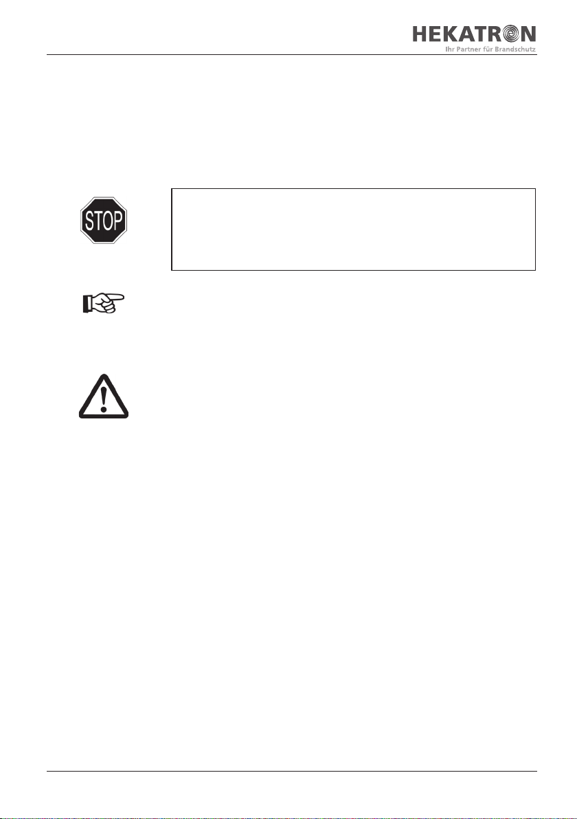
A note informs you about special features of the unit, explains important
circumstances, or recommends special procedures.
Warning of potential damage to equipment!
This symbol is used to indicate information that is important for correct
operation of the unit. Any neglect of this warning may result in damage to
the device.
Danger!
This symbol is used to indicate information that is of crucial importance for
health and safety of persons. Any neglect of this symbol may result in damage
to health and personal injury.
5/68
7002985 300709.KET Release 06.06.2017 Hekatron Vertriebs GmbH · Brühlmatten 9 · D-79295 Sulzburg
2 Safety
2 Safety
Observe and follow the instruction manual!
The following instructions do not provide a complete list of all binding standards
and regulations. Particular cases of application may require that additional regula-
tions, findings and state-of-the-art skills should be considered.
Observe the instruction manual!
The SVG 522 instruction manual is an integral part of the product. Before
handling, installing and commissioning the SVG 522 power supply unit, the
following safety instructions as well as descriptions and information about the
present Instruction manual must be carefully read and observed.
It is a fundamental rule that, when planning, installing, assembling, and
operating the hold-open system, specific national rules and regulations must
be observed. In any case, any specific national provisions have priority over
the following project planning instructions.
Avoid damage to markings!
The type plates, type designations and/or identification markings on the
devices and printed circuit boards must not be removed, overwritten, or made
illegible.

6/68
Hekatron Vertriebs GmbH · Brühlmatten 9 · D-79295 Sulzburg 7002985 300709.KET Release 06.06.2017
2 Safety
2.1 General safety information and
protective measures
Instructions applicable in Germany
The test regulations of the Deutsches Institut für Bautechnik (DIBt) and the
respective building inspectorate approval must be observed and followed
when planning, assembling, installing and operating hold-open systems on
fire barriers.
The information contained in this instruction manual is based on these
regulations.
Ensure proper use!
– The technical data stated on the equipment must be observed.
– Modifications or changes to the equipment are not permitted.
– The equipment may only be operated when it is in undamaged and perfect
condition and only for its intended purpose.
– No other spare parts than the original ones available from the
manufacturer must be used.
– The equipment may only be repaired by the manufacturer's instructed and
authorised personnel.
– The allowed components of the hold-open system are listed in a separate
building inspectorate approval.
– Doors and gates – mechanical aspects. In its version of August 2000,
DIN EN 12604 specifies basic mechanical requirements for doors and gates
which are provided for installation in areas that are accessible to persons.
Their intended use requires that safe access should be possible for goods
and vehicles that are accompanied by persons. The doors and gates may be
actuated manually or power-operated.
The above instructions are completed by various regulations under the regime of
the Equipment Safety Act as well as technical measures for occupational safety
and health that are to be taken into account. Accident prevention regulations,
the professional associations' directives or other requirements some of which are
applicable to specific installations must also be taken into account.
We recommend that, based on the system of rules, the operator should set up
a safety concept and/or fire protection concept which provides for a detailed risk
analysis. In this process, basic principles should be set up in a specific order.

7/68
7002985 300709.KET Release 06.06.2017 Hekatron Vertriebs GmbH · Brühlmatten 9 · D-79295 Sulzburg
2 Safety
Safety measures must always be taken in a specific order.
The subsequent risk analysis should particularly include the following issues:
– Identification of fire and accident risks to which the employees may be exposed
– Selection of appropriate measures to ensure that safety requirements will
be met
– Safe design, operation and maintenance of work equipment, warning and
safety devices
Hold-open systems are subject to the duty of servicing required according to
DIN 31051 and DIN 14677. More information can be found in the respective
approval document of the hold-open system.
If the use of the system is changed, it must be verified whether the legal provi-
sions, requirements and state of the art are appropriately taken into account.
Specialised staff must be provided for projecting, assembling and commissioning.
When working on electrical installations, special regulations must be
complied with.
Such work may only be carried out by authorised qualified electricians.
Principle under building law:
All persons involved in a construction project must comply with all principles and
provisions under building law by themselves without needing a special note from
the Construction Supervisory Board. This is applicable for building owners, design
writers, design planners, contractors, and operators.
Special notes:
Please observe the following provisions for hold-open systems in
potentially explosive areas:
– SVG 522 equipment must not be used in hold-open systems for
potentially explosive areas.

8/68
Hekatron Vertriebs GmbH · Brühlmatten 9 · D-79295 Sulzburg 7002985 300709.KET Release 06.06.2017
2 Safety
2.2 Intended use
The SVG 522 device is a power supply unit to be used in hold-open systems and
fire barriers within the scope of path-bound conveying systems. When being part
of a hold-open system, the SVG 522 may only be operated in connection with
a TSK 03, FAK 01 or FAD 01. While the device is commissioned and operated, it
is absolutely necessary that the safety instructions as well as acceptance and test
rules of this instruction manual should be observed.
2.2.1 Hold-open systems for fire barriers
For reasons of structural fire protection, buildings are subdivided into fire zones
by means of closed fire doors. In the event of fire, smoke will therefore be
restricted to the fire zone affected, escape routes will remain passable, and rescue
work will not be interfered. Since closed fire doors often interrupt operating
procedures, hold-open systems are installed which automatically close open fire
doors in the event of fire.
When the SVG 522 power supply unit is used to supply hold-open systems
with energy, use must be made either of the door control board TSK 03 or the
hold-open system board FAK 01 (FAD 01).
To store the alarm state of the system, the extension board SAB 04 must be used.
2.2.2 Hold-open system for fire barriers within the scope of path-bound
conveying systems
When the SVG 522 power supply unit is used to supply hold-open systems
with energy, use must be made of the door control board TSK 03.
System components:
a) Hold-open system for fire barriers within the scope of path-bound conveying
systems, consisting of:
– Smoke switch/thermal switch to detect a fire and automatically trigger the
hold-open device
– Electromagnetic door retainer to lock the barrier
– Manual release button to manually release the fire barrier
– Safety devices (for example, light barriers, etc.)
– Hold-open system power supply
b) Conveying system: The conveying system and the related regulations are
included in the technical documentation issued by the manufacturer of the
conveying system.
c) Fire barrier: The fire barrier must meet legal and fire-protection requirements.
Fire barriers of conveying systems must be made and installed such that,
while they are closed, the transfer of fire is prevented for a certain burn time.
See DIN 4102 ff. Suitability must be verified.

9/68
7002985 300709.KET Release 06.06.2017 Hekatron Vertriebs GmbH · Brühlmatten 9 · D-79295 Sulzburg
2 Safety
Appropriate measures must be taken to ensure that the closing operation
will not be impeded by the conveying system or by transported material. This
requirement applies both to the operating state and a failure of the system.
2.2.3 Hold-open system for fire barriers in relation with the control of
side and cover flaps.
The suitability of the flap elements (top and/or side flaps) has been verified by a
separate mechanical functional test. The results of this test can be included in the
approval document for the sliding door or gate. The sliding door or gate must
be of the self-closing type. This function of the sliding door or gate must not be
impaired by the flaps that have been added.
The cover flaps can be opened with gas springs, steel tapes or other elements.
The cover flaps are kept closed by electromagnetic retainers that are listed in the
relevant approval document for the hold-open system.
There are two types of cover flaps:
a) Top flaps
b) Recess flaps or side flaps (inlet side and inlet opposite side)
When the system is installed, moving parts must be prevented from having
a negative effect on each other.
The use of the sliding door or gate with cover flaps and a hold-open system with
extended flap functionality is defined in the respective approval document.
Hold-open system configuration:
The hold-open system is extended by the functionality of energising the side/cover
flaps on sliding doors and gates.
When cover flaps are used on sliding doors and gates, it must be ensured that
the sliding door or gate starts with a delay in relation to the opening of the
cover flaps.
Top and side flaps must not impair each other.
Generally, the hold-open system must feature a battery-buffered energy
supply unit.
All control elements must be connected to a battery-buffered energy supply
unit.
If there is no primary energy supply (230 V AC), the system can be reliably
closed by the equivalent power supply (batteries).
The SVG 522 power supply unit is provided with the additional door control
board TSK 03. The door control board TSK 03 is a control and connection
board for hold-open systems.

10/68
Hekatron Vertriebs GmbH · Brühlmatten 9 · D-79295 Sulzburg 7002985 300709.KET Release 06.06.2017
2 Safety
2.3 Warranty claims
In case of non-compliance with the information contained in this instruction man-
ual, any claims for warranty and liability of the manufacturer of the SVG 522 will
become invalid. In particular, the device or its components may only be repaired
by the manufacturer's instructed and authorised personnel. Non-compliance with
this clause will result in any claims for warranty and liability against the manufac-
turer of the SVG 522 device becoming null and void.
The information and warranty conditions stated in the
General Terms and
Conditions
of Hekatron Vertriebs GmbH, Brühlmatten 9, D-79295 Sulzburg are
applicable.

11/68
7002985 300709.KET Release 06.06.2017 Hekatron Vertriebs GmbH · Brühlmatten 9 · D-79295 Sulzburg
3 Product description
3 Product description
3.1 SVG 522
The SVG 522 power supply unit with battery buffer (part no. 5400085.0201)
consists of the power supply board SVK 47 and a stable industrial housing
made of sheet steel and having degree of protection IP 54. The SVG 522
is of the wall-mounted type. An assembly kit for wall-mounting with lugs
(part no. 6100038) is available for individual assembly. Cable entries are provided
on the top side of the housing. Indicators for the power supply unit and optional
door control board TSK 03 as well as acknowledgement options are incorporated
in the keypad on the door front of the housing. Labelling fields can be exchanged
as desired. The SVG 522 version with TSK 03 (part no. 5400085-0210) already
features the installed and pre-wired door control board TSK 03.
The SVG 522 complies with the standards and directives EN 54-4 and VdS 2541
as well as the DIBt provisions and was primarily developed for use in hold-
open systems and path-bound conveying systems. It is intended for bat-
tery-buffered direct current supply of the door control boards TSK 03 and
FAK 01/FAD 01 according to standards. These door control boards are used to
supply and evaluate peripheral devices, such as smoke switches, electromag-
netic door retainers, light barriers, and signalling means.
The user has the option of installing either two hold-open system boards
FAK 01 or one door control board TSK 03 in the SVG 522.
Features:
The SVG 522 is characterised by the following features:
– Short-circuit-proof
– Primary clock pulses
– High efficiency
– Maintenance-free emergency power supply
– Audible and visual indication of power, battery and fuse failures as well as low
voltage and earth fault
– Potential-free changeover relay for power failure, low voltage and battery
failure
– Ready indicator
– Temperature-dependent trickle charge
– Batteries protected against total discharge
– Installation slot for door control board TSK 03 or 2 FAK 01
– DIBt approval for hold-open systems Z-6.5-1725
DIBt approval for path-bound conveying systems Z-6.5-1891
– VdS tested
12/68
Hekatron Vertriebs GmbH · Brühlmatten 9 · D-79295 Sulzburg 7002985 300709.KET Release 06.06.2017
3 Product description
Protection against total discharge
Totally discharged batteries may be permanently damaged. The end-of-dis-
charge voltage must not fall below the value specified by the manufacturer.
The total discharge range starts below this voltage. In the event of a power
failure, the SVK 47 power supply unit constantly monitors the battery dis-
charge state. Once the end-of-discharge voltage is reached, the power supply
unit automatically disconnects the consumers from the batteries. This is called
load shedding.
The following must be observed in the event of power failure
In order to ensure operation as prescribed in the event of power failure, a
buffered standby current must be available for up to 4 hours as well as an
additional buffered alarm current for half an hour. Moreover, totally dis-
charged batteries must be able of being recharged to 80 % of their capacity
within a charging time of 24 hours (EN 54-4, VdS 2095).
Current limiting / charging current distribution
The SVG 522 can be charged with a maximum of 2 A.
The total current is distributed among the charging current and the consumer
current. While the batteries are completely charged, a maximum of 2 A is
theoretically available for the consumers. This current is reduced if charging
current is required.
Distribution of the total current for the SVG 522 when two
12-V/7.2-Ah batteries are used:
Distribution of the total current for the SVG 522 when two 12-V/7.2-Ah
batteries are used:
Reserved charging current: 700 mA Current available for consumers: 1.3 A
Example calculation of the battery capacity according to EN 54-4:
SVG 522 with connected consumers:
Standby current with consumers (I
STANDBY
): 1.2 A
Override time (T
O
): 4 h
Alarm current with consumers (I
ALARM
): 1.3 A
Alarm time (T
A
): 0.5 h
Battery capacity needed for the required override time 4.8 Ah
Current required for an alarm time of 0.5 h 0.65 Ah
Total battery capacity required:
5.45 Ah
(without taking the voltage drops at the supply lines into account)
Result:
Based on the battery capacity, an SVG 522 with a battery pair of 7.2 Ah can
therefore supply the system with current for a time period of more than 4 hours
(acc. to EN 54-4)
13/68
7002985 300709.KET Release 06.06.2017 Hekatron Vertriebs GmbH · Brühlmatten 9 · D-79295 Sulzburg
3 Product description
Battery monitoring
For battery monitoring purposes, the batteries are loaded at cyclic intervals
of 60 sec during mains operation, while the voltage is measured at the same
time. An aged or defective battery is signalled by the "collective fault" LED
which lights up on the SVK 47 board and the "failure" indicator which lights
up simultaneously on the display and operator panel.
Status monitoring
:
The SVK 47 board provides 3 potential-free changeover contacts which separately
indicate the following states:
– Power failure
– Total discharge
– Collective fault (battery and processor)
The SVG 522 which is provided with the door control board TSK 03
(part no. 5400085-0210) has the collective fault and total battery discharge
output already pre-wired to the alarm evaluating unit of the TSK 03 at the
factory.
Usable battery types
The only battery types allowed to be installed are 12-V/7.2 Ah batteries
tested by VdS. We recommend to install emergency power batteries BA-7.2
Ah (part no. 30-2310002-01-xx). Two 12-V/7.2 Ah batteries must be taken into
account.

14/68
Hekatron Vertriebs GmbH · Brühlmatten 9 · D-79295 Sulzburg 7002985 300709.KET Release 06.06.2017
3 Product description
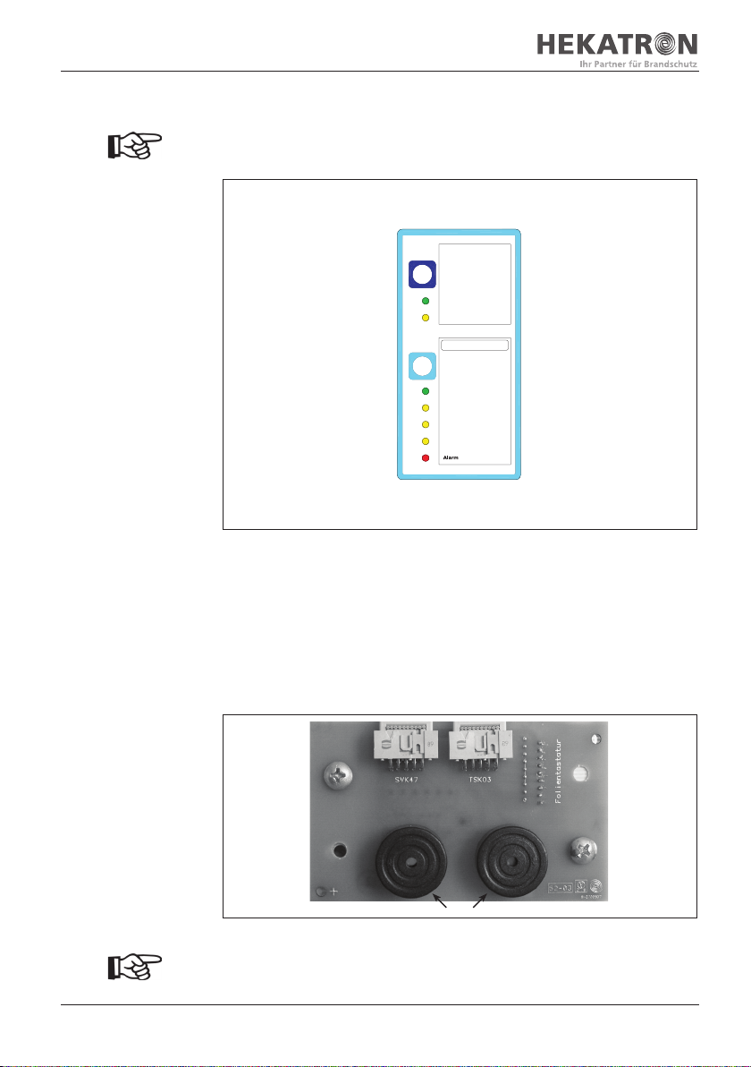
3.2 Indicators
Indicators for the power supply unit and optional door control board TSK 03 as
well as acknowledgement options are incorporated in the keypad on the door
front of the housing. Labelling fields can be exchanged as desired.
The SVG 522 version without door control board TSK 03 has the labelling field
"Door control board" already inserted into the labelling space on its rear side
(white area). If the door control board TSK 03 is installed subsequently, the
labelling field can be taken out of the labelling space laterally and re-inserted
with the "Door control board" labelling being visible.
Netzteil (Power Supply Unit)
Akustik aus (Audio off)
Türsteuerkarte
(Door control board)
Akustik aus / Reset
(Audio off / Reset)
Betrieb (Operation)
Tür auf (Open door)
Tür zu (Close door)
Störung (Fault)
Betrieb (Operation)
Störung (Fault)
Fig. 01: Labelling field for the TSK 03 on the operator panel
3.2.1 Display and operator panel for the power supply unit
"Akustik aus" button
(audio off):
The audible warning signal
is reset in the event of a fail-
ure of the power supply unit
(battery or power failure,
processor fault, total dis-
charge, earth fault).
"Betrieb" indicator
(operation):
Indicates that the power
supply unit is in operation.
"Störung" indicator (fault):
Indicates battery or power
failure
(see p. 26, table-01).
Netzteil (Power Supply Unit)
Akustik aus
(Audio off)
Betrieb (Operation)
Störung (Fault)
Fig. 02: Operator panel for the power supply unit
15/68
7002985 300709.KET Release 06.06.2017 Hekatron Vertriebs GmbH · Brühlmatten 9 · D-79295 Sulzburg
3 Product description
3.2.2 Display and operator panel for the door control board TSK 03
The reset/alarm acknowledgement function can only be performed if there is
no alarm criterion present for a time period of at least 30 seconds.
"Akustik aus/Reset" button
(audio off/reset):
The audible warning signal
is reset if the connected light
barrier and reset function
(alarm acknowledgement)
have failed/are disabled after
an alarm has been triggered.
"Betrieb" indicator
(operation):
Indicates that the door control
board TSK 03 is in operation.
"Tür auf" indicator
(Open door):
Indicates that the door is
open (optional connection).
"Tür zu" indicator
(Close door):
Indicates that the door is
closed (optional connection).
"Störung" indicator (failure):
Indicates that the connected
light barrier has failed/is
disabled (optional setting).
"Alarm" indicator:
The indicator flashes and is red:
An alarm criterion is pend-
ing; the set time is elapsing.
The indicator emits steady
light and is red:
Closing has been initiated.
Türsteuerkarte
(Door control board)
Akustik aus / Reset
(Audio off / Reset)
Betrieb (Operation)
Tür auf (Open door)
Tür zu (Close door)
Störung (Fault)
Fig. 03: Operator panel for the door control board TSK 03
3.2.3 AFT 01 board for the operator panel inside the door
The display keypad AFT 01 serves as interface between the power supply unit
board SVK 47 of the optional door control board TSK 03 and the display and
operator panel. In addition, 2 audible signal transducers are integrated and are
energised internally.
The left-hand ribbon cable connector is connected to the power supply unit board
SVK 47. The right-hand ribbon cable connector of the SVG 522 version with TSK 03
is connected at the factory.
SVK 47
TSK 03
Audible signal transducers
Fig. 04: AFT 01 board inside door
If the TSK 03 board is installed subsequently, the connection from the TSK 03
to the AFT 01 must still be made (ribbon cable included in the TSK 03 delivery).

16/68
Hekatron Vertriebs GmbH · Brühlmatten 9 · D-79295 Sulzburg 7002985 300709.KET Release 06.06.2017
3 Product description
3.3 TSK 03 option
The TSK 03 door control board (part no. 5300680-0201) is mainly used to evaluate
and control hold-open systems with light barrier monitoring and path-bound
conveying systems.
It features inputs for automatic fire detector evaluation, manual release, light
barriers and door limit switches. Separate outputs are provided for energising
hold-open devices as well as visual and audible signal transducers.
Potential-free and switched outputs, such as alarm, light barrier failure, initiated
closing operation and door end switch evaluation are provided as interface to an
existing building control system or conveying system.
The board features setting options for configuring the system and additionally
allows setting delay times for the connection of hold-open devices
(see chapter 7.1).
The SVG 522 features a slot for installation of the TSK 03.
Features:
The door control board is characterised by the following features:
– Monitoring and evaluation of the connected smoke switches
– Monitoring and evaluation of the connected light barrier
– Configuration as monitoring unit with or without personal protection
– Optional evaluation of the disabled light barrier
– Evaluation of the connected manual release buttons
– Separate input for additional manual release with or without energisation of
the alarm output (can be configured as desired)
– Option of including delay times for the closing operation
– 4 inputs for door limit switches; 2x for "Open door" and 2x for "Close door"
– Separate input for reset function
– "Alarm" info as potential-free changeover contact; an additional output with
potential
– "Light barrier failure" info as potential-free changeover contact; an additional
output with potential
– "Closing initiated" info as potential-free changeover contact; an additional
output with potential
– "Open door" info as potential-free changeover contact; an additional output
with potential
– "Close door" info as potential-free changeover contact; an additional output
with potential
– Actuators for hold-open devices
– Actuators for visual and audible signal transducers

18/68
Hekatron Vertriebs GmbH · Brühlmatten 9 · D-79295 Sulzburg 7002985 300709.KET Release 06.06.2017
3 Product description
3.4 FAK 01/FAD 01 option
The hold-open system board FAK 01 (part no. 6300116) can be installed as an
alternative to the door control board TSK 03 and is mainly used for evaluating and
controlling conventional hold-open systems.
It features an input for evaluating the automatic fire detection elements and the
manual release. The hold-open devices are energised via a switched output.
In addition, the "Alarm" info can be separately output via a potential-free
changeover contact.
The FAD 01 can be provided with the additional board SAB 04 (part no. 4400043)
for the purpose of alarm storage.
The SVG 522 features two slots for installation of the FAK 01.
The FAK 01 board is also available as surface-mounted board with its own
housing. The name of the board incl. housing is FAD 01 (part no. 5700103).
They can therefore also be mounted separately.
Using multiple FAK 01/FAD 01 boards
If multiple FAK 01/FAD 01 boards are used, the total current available must
be noted (see chapter 3.1 "Design and operating principle of the SVG 522 >
Current limiting / charging current distribution).
Slot for additional
board SAB 04 with the
FAK 01/FAD 01
Fig. 06: Hold-open system board FAK 01/FAD 01

19/68
7002985 300709.KET Release 06.06.2017 Hekatron Vertriebs GmbH · Brühlmatten 9 · D-79295 Sulzburg
3 Product description
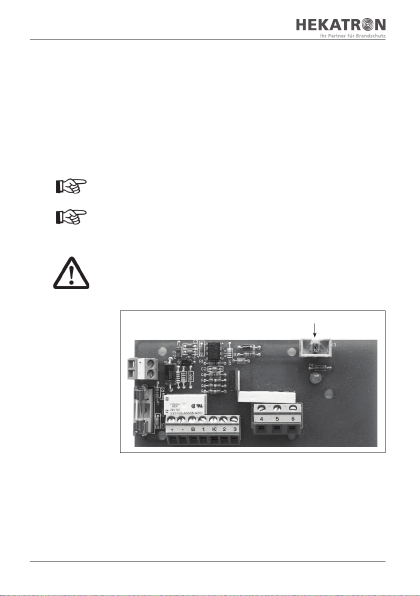
3.5 Flap control option
Where sliding doors and gates with extended flap functionality are concerned,
the door control board TSK 03 allows opening the side flaps with a delay in
relation to the top flap. To achieve this, the alarm output of the TSK 03 can be
used to open the top cover.
The output for the hold-open device is used for the delayed energisation of the
side flaps. The delay can be set within a range from 0 to 120 seconds in 10-second
increments. An additional delay of 2 minutes and 10 minutes is available.
Alarm relay
Fig. 07: Alarm relay
The TSK 03 detects the alarm message; the alarm relay is energised instantly and
triggers the top flaps.
Terminals 53/54 and
terminals 55/56 are both
de-energised after the
set time has elapsed
(see chapter "Hold-open
device connection")
Hold-open device
1
Fig. 08: Hold-open device 1
After the time set on the TSK 03 has elapsed, terminals 53/54 and 55/56 are
de-energised. In the connection example above, terminals 53/54 are used to open
the side flaps with a delay and terminals 55/56 are used to release the door or
gate holding magnets with a delay.
Hold-open devices for the flaps
The hold-open devices for the flaps must be listed in the DIBt approval
document for the hold-open system.

20/68
Hekatron Vertriebs GmbH · Brühlmatten 9 · D-79295 Sulzburg 7002985 300709.KET Release 06.06.2017
4 Scope of delivery and transport
4 Scope of delivery and
transport
The SVG 522 is delivered in an appropriate cardboard packaging that is sealed
with an adhesive tape. The packaging can be recycled and reused.
Scope of delivery of SVG 522 (part. no. 5400085-0201):
– 1 housing with built-in power supply board
– 19 sarel plugs
– 1 M20 cable gland
– 2 battery holding brackets
– 4 allen screws
– 1 cable kit for battery fuse
– 1 instruction manual
Scope of delivery of SVG 522 with TSK 03 (part. no. 5400085-0210):
– 1 housing with built-in power supply board
– 19 sarel plugs
– 1 M20 cable gland
– 2 battery holding brackets
– 4 allen screws
– 1 cable kit for battery fuse
– 1 door control board TSK 03, mounted and pre-wired
– 2 resistors 10 kΩ
– 1 resistors7.5 kΩ
– 10 diodes 1N4007 DO-41
– 1 instruction manual
Scope of delivery of TSK 03 (part. no. 5300680-0201):
– 1 door control board TSK 03
– 1 ribbon cable for AFT 01
– 6 PCB holders
– 2 resistors 10 kΩ
– 1 resistors7.5 kΩ
– 1 instruction manual
Packaging instructions
The cardboard packaging is suitable for being shipped by mail or rail to a
limited extent only. Special packaging is available for transports to tropical
zones, transports by sea, etc. For more information, please contact the
manufacturer.
Table of contents


