Aspect LED AL-PS-W-D-20-24V User manual
www.aspectled.com
Copyright © 2014-2018. ASP Holdings, Inc.
20W and 45W Dimmable LED
Power Supply
INSTALLATION GUIDE

1
20W AND 45W DIMMABLE POWER SUPPLY INSTALLATION GUIDE
Copyright © 2014-2018. ASP Holdings, Inc. Have questions? Call 888-503-1317
aspectLED oers a full line of dimmableLED power supplies
(drivers). A high quality dimmablepower supply results in your LED
lights using less energy, shining brighter, and lasting longer. That’s
why aspectLED oers the highest quality dimmableLED power
supplies. Our power supplies can be used with a wide variety
of incandescentdimmer switches. All of our power supplies are
energy efficient and eco-friendly.
Our power supplies feature exible input voltage (90-135VAC) and
come in12VDC or 24VDC voltage output. Wattage displayed is the
Maximum Wattage.
Overview
MODELS
Dimmable Power Supply Wattage
20W
45W
Maxium Continuous Wattage
16W
36W
SKU
AL-PS-W-D-20-24V
AL-PS-W-D-45-24V
Dimensions
5-1/2” long
1-3/4” wide
1-1/8” thick
7-1/8” long
2-3/8” wide
1-1/2” thick
• Install in accordance with the National Electric Code, and all local regulations.
• This product is intended to be installed and serviced by a qualied licensed electrician.
• Only use with compatible LED xtures, controls and dimmer switches. Only use copper wiring.
• Proper heat dissipation will prolong the working lifespan of this product. Install in well-ventilated area free from
explosive gases and vapors.
• Ensure appropriate type and size wire is installed between driver, xture, and any controls in between. When
choosing wire, factor in voltage drop, amperage rating, and type (in-wall rated, wet location rated, etc). Improper
wire type could overheat wires, and cause a re.
• Do not install if product has any visible damage.
• Do not modify or disassemble this product beyond instructions or the warranty will be void.
• Use only constant voltage xture that are marked Dimmable with your dimmable LED power supply.
SAFETY AND WARNINGS
SPECIFICATIONS
Input Voltage
Output Voltage
Ambient Temperature
Minimum Load
Maximum Load
90 to 135 VAC, 50/60Hz
See driver label
-4 Degrees to 104 Degrees Fahrenheit (-20 Degrees Celsius to 40 Degrees Celsius)
≥ 60 % to ensure ideal dimming performance
Refer to derating curve
(drivers). A high quality dimmablepower supply results in your LED
lights using less energy, shining brighter, and lasting longer. That’s
why aspectLED oers the highest quality dimmableLED power
of incandescentdimmer switches. All of our power supplies are
2
20W AND 45W DIMMABLE POWER SUPPLY INSTALLATION GUIDE
Copyright © 2014-2018. ASP Holdings, Inc.
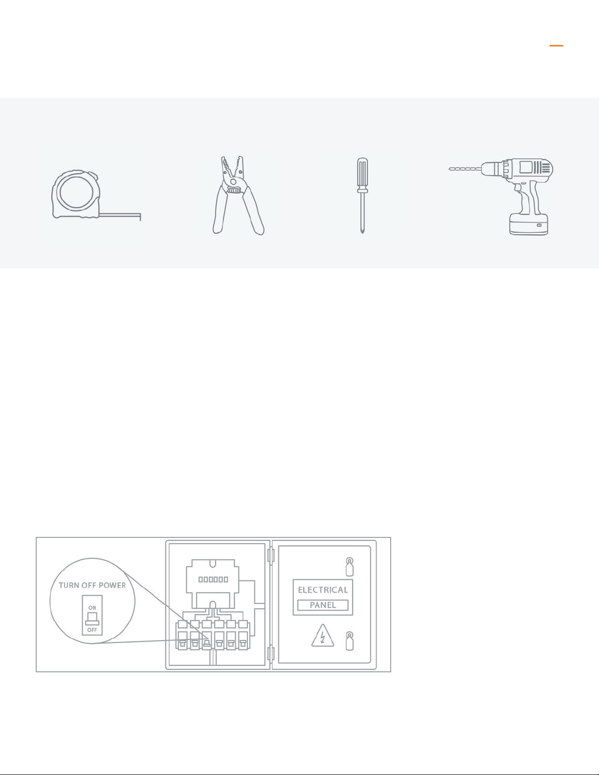
TOOLS YOU’LL NEED
Tape Measure Wire Stripper Screw Driver Drill (Optional)
Before you begin
We know how boring it can be to read instructions, so we’ll keep this installation guide as short and sweet as possible.
Before you begin with your installation, be sure to fully read these instructions. They contain many useful tips and
pointers that will help to ensure a perfect installation, save you time, and ensure your safety.
It is important that you install this product (and all other electrical products) in accordance with the National Electric
Code (NEC) and all applicable local building and electrical codes for your area. If you are unfamiliar with the NEC,
your local building/electrical codes, and/or the proper installation methods for electrical devices, you should hire a
qualied and licensed electrician to do the work for you.
Before beginning any electrical work, always
disconnect power at the fuse or circuit breaker.
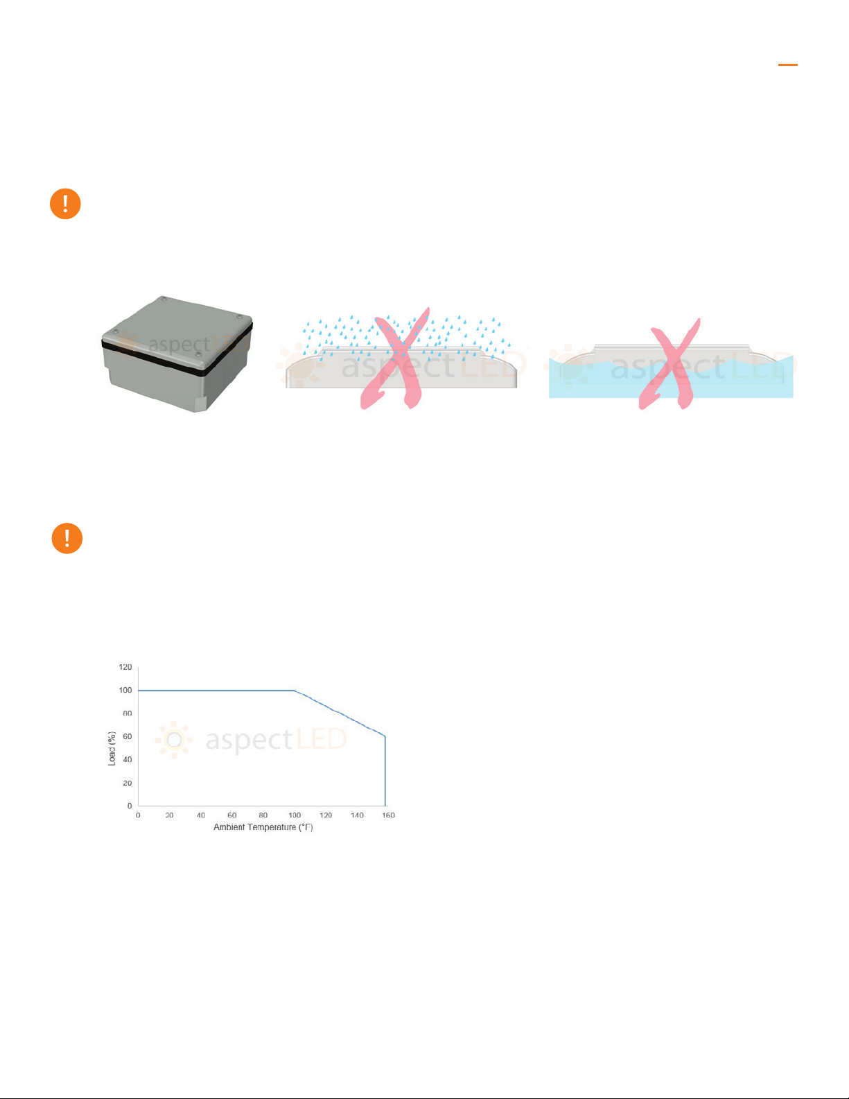
Figure 1. Weatherproof
electrical enclosure
Figure 4. Derating curve
Figure 2. This power supply is not
suitable for wet location use.
Figure 3. This power supply is not
submersible.
3
20W AND 45W DIMMABLE POWER SUPPLY INSTALLATION GUIDE
Have questions? Call 888-503-1317
Important considerations
This xture is suitable for use in dry or damp locations.
When using this xture in exterior damp locations, it must be installed where it is protected from rain or other
moisture by installing in a weatherproof electrical enclosure like the one shown in Figure 1.
This product is suitable for environments of ambient temperatures
between -4°F to 104°F (-20°C to 40°C).
It is important that power supplies are not installed outside this range. Precautions should be taken when
installing in ambient temperatures of over 100°F to avoid overheating and damage to the driver. Refer to the
derating curve in Figure 4.
Copyright © 2014-2018. ASP Holdings, Inc.
*Drivers may not require a framed ground connection.
^Ensure to load the driver at least 60% the labeled load for proper dimming performance.
*^
*^
4
20W AND 45W DIMMABLE POWER SUPPLY INSTALLATION GUIDE
Have questions? Call 888-503-1317
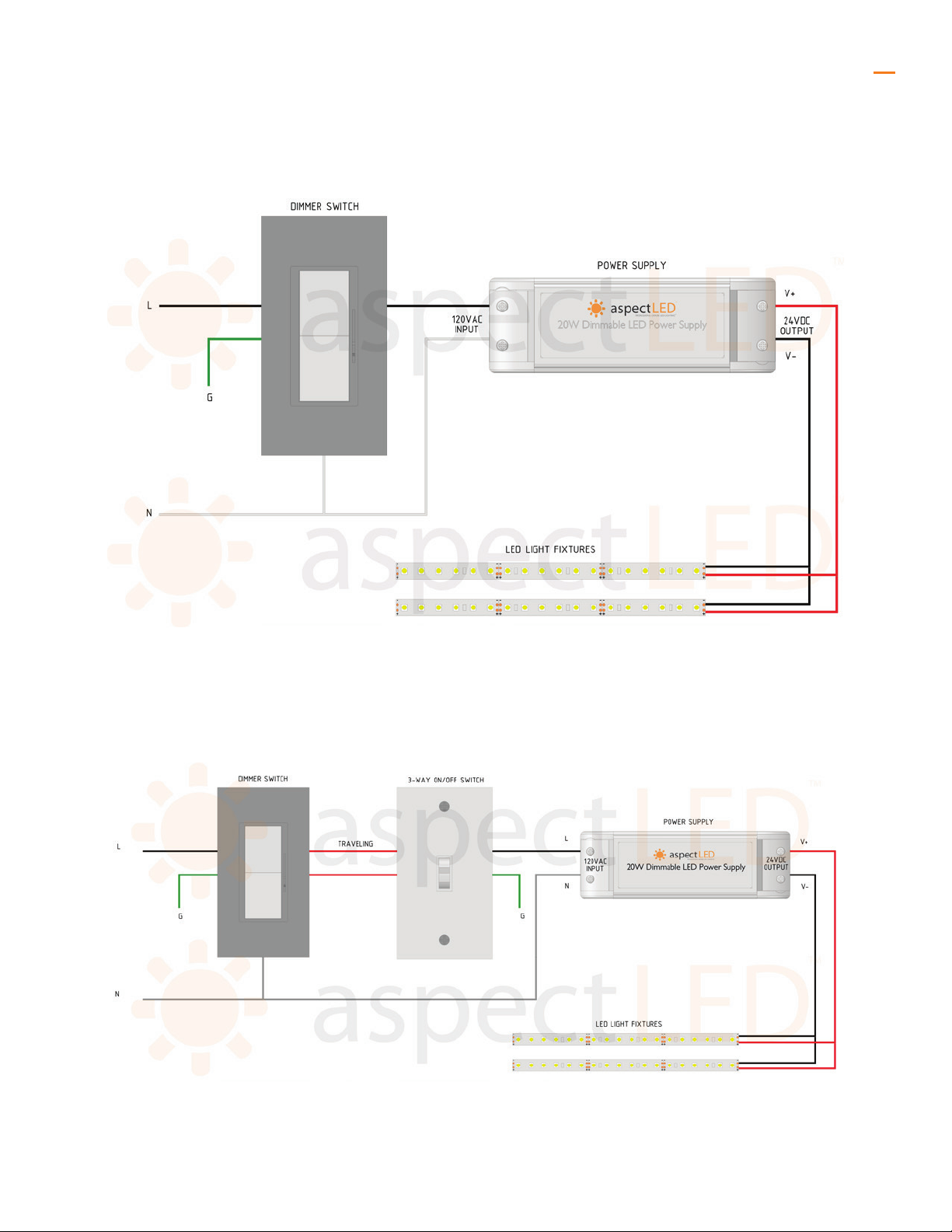
System diagram: standard
System diagram: 3-way
Copyright © 2014-2018. ASP Holdings, Inc.

Drivers housed in a non-conductive plastic casing don’t
required a framed ground connection if a framed ground
connection is not required. When utilizing 3- conductor cables,
trim the ground wire ush with sheathing. Make sure that the
wire sheathing is set on top of the wire strain relief once covers
are reattached.
5
20W AND 45W DIMMABLE POWER SUPPLY INSTALLATION GUIDE
Wiring connections: 24VDC 20W
power supply
Wiring connections: 24VDC 45W
power supply
Have questions? Call 888-503-1317Copyright © 2014-2018. ASP Holdings, Inc.

Dimmer or On/O Switch Power Supply LED Light Fixture
Use a wire stripper to expose the bare stranded copper wire before placing
on top of the metal plates in the screw terminal. Use a mini Phillips or
athead screwdriver to turn screw clockwise to raise metal plate and clamp
wire. Screw terminals t up to 12AWG solid-core copper wire.
DO NOT place wire underneath plate and clamp by screwing
counterclockwise.
Use a screwdriver and screws for attaching the power supply to sturdy
surface. Remove the wiring compartment access covers using a screwdriver.
6
20W AND 45W DIMMABLE POWER SUPPLY INSTALLATION GUIDE
Installation
Determine a suitable location to install the 3 components, as labeled in
System Diagram.
1
These components will include suitable wire installed between the power supply, the LED light xture, and
any controls or dimmer switches. It is important to choose the correct wire for the specic application, this is
dependent on voltage drop, amperage rating, and environment. Please consult a voltage drop and wire sizing
chart to determine adequate wire size. Using the incorrect wire size will damage your products and pose a re
risk! If installing wiring in a wall or ceiling, always use appropriately rated in-wall wiring.
Using the two mounting holes as labeled in Wiring Connections,
fasten the driver to a sturdy surface in the desired orientation using
appropriate screws and screwdriver.
2
Have questions? Call 888-503-1317Copyright © 2014-2018. ASP Holdings, Inc.
Wiring
Compartment
Access Cover
7
20W AND 45W DIMMABLE POWER SUPPLY INSTALLATION GUIDE
Attach your LED light xtures (making sure the load is at least 60%
the power supply’s labeled load) and dimmer switch by referring to
the System Diagram and installation guides for both the lights and
dimmers available at www.aspectled.com.
When installing in ambient temperatures that may reach over 100°, refer to the derating curve in Figure 4 to
avoid overheating and damage to the driver.
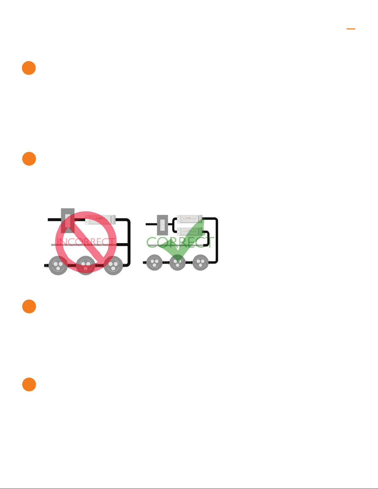
Do not install dierent LED xture types on the same power supply as
ickering and faulty dimming may occur.
Before reconnecting power at the fuse or circuit breaker, install any additional components and verify all
connections.
Once you’ve nished, double check all connections and turn on power
to your circuit.
Test functionality of your installation. If you experience any issues, immediately disconnect power to your
installation and see the trouble shooting guide on page 9, or contact technical support at (888) 503-1317
Congratulations!
You’ve successfully completed the installation process. Once your light is installed, your project is nished.
Now is a great time to take a moment to sit down and enjoy your favorite beverage while giving yourself a pat
on the back for a job well done.
3
4
5
6
Have questions? Call 888-503-1317Copyright © 2014-2018. ASP Holdings, Inc.

We’re always here to help!
Feel free to contact our electrician’s help desk at (888) 503-1317 option 3, or suppor[email protected].
See our list of compatibility tested dimmer switches on www.aspectled.com.
8
20W AND 45W DIMMABLE POWER SUPPLY INSTALLATION GUIDE
Troubleshooting
Dimmer compatibility
Have questions or need assistance?
Lights are ashing
Lights are not dimming
Lights are not illuminating
Dierent light types do not dim on sync
Installation trips main breaker
• Ensure a compatible constant voltage dimmable xture is installed.
• Verify a compatible dimming switch is installed. If ickering is apparent at low light levels, install a compatible
trim-adjustable dimming switch.
• Make sure the driver is not overloaded.
• Ensure correct input voltage
• Check that all connections are properly secured.
• Make sure dierent light xture types are not connected to the same driver, as dierent types of xtures must
be connected to their own individual drivers.
• Ensure a compatible constant voltage dimmable xture is installed.
• Ensure a compatible dimmer switch is installed and wired correctly.
• Check System Diagram, Wiring Connections and installation guides of all components.
• Ensure the system is wired correctly and positive connections are connected to positive, and negative
connections are wired to negative.
• Ensure a compatible constant voltage dimmable xture is installed.
• Make sure dierent light xture types are not connected to the same driver. Dierent xtures must be
connected to their own individual drivers.
• Check wiring for a short circuit. If breaker continues to trip, there might be a short in your circuit. Call a licensed
electrician for assistance.
Have questions? Call 888-503-1317Copyright © 2014-2018. ASP Holdings, Inc.
This manual suits for next models
1
Table of contents
Popular Power Supply manuals by other brands


SLAT
SLAT Evolution operating instructions

Transition Networks
Transition Networks E-MCC-1600 installation guide

Bentel Security
Bentel Security BXM12/30-U installation manual

Solar Stik
Solar Stik 24VDC PRO-VERTER 5000-220 AGS Programming instructions

Thermal Dynamics
Thermal Dynamics MERLIN 3000 Service manual

Cross Technologies
Cross Technologies 2000-16-3624 instruction manual


