4RKE 1500W 021617
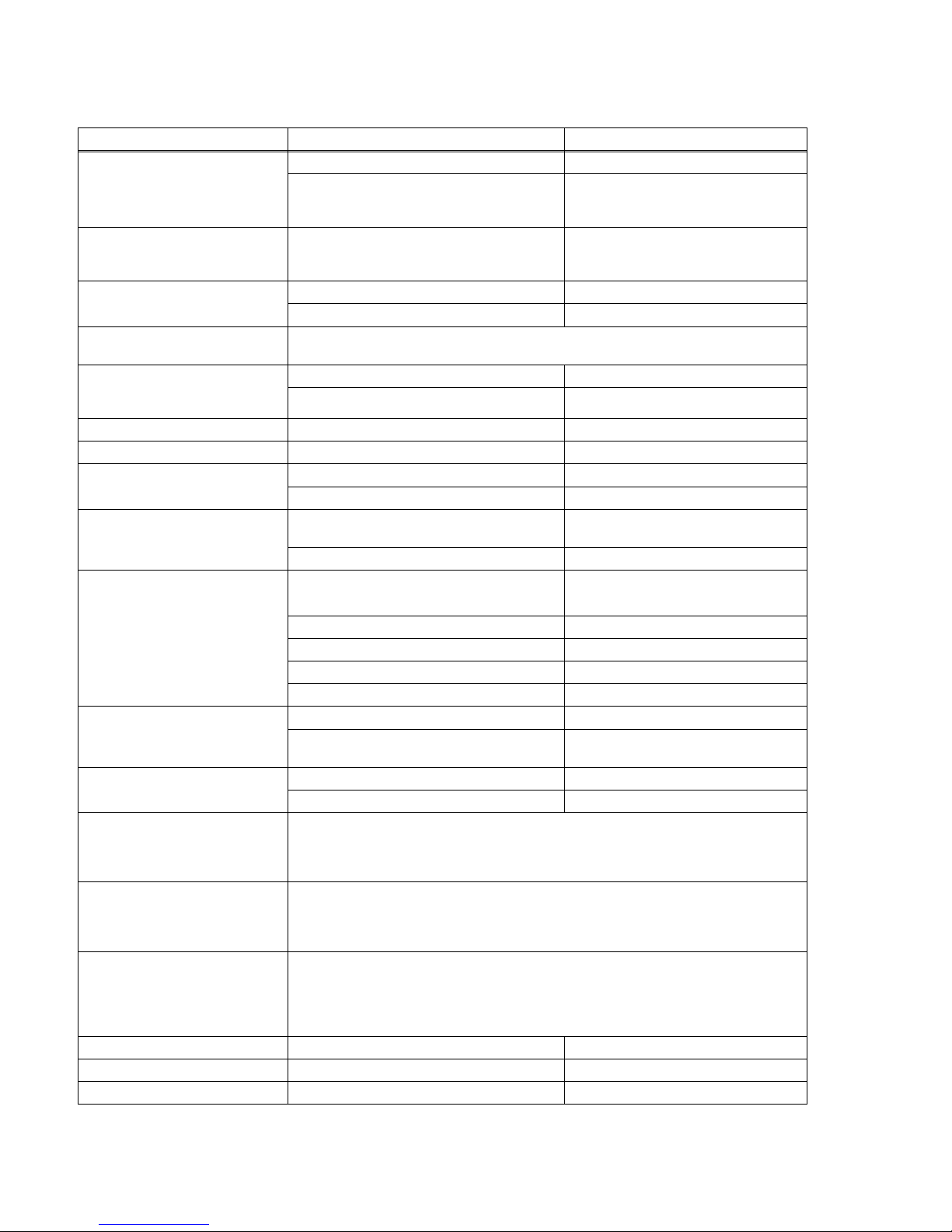
TABLE 2. POWER SUPPLY RATINGS AND SPECIFICATIONS
CHARACTERISTIC SPECIFICATION CONDITION/NOTES
Input Voltage Nominal 100-240V a-c, Range: 85-265V a-c (0 to 100% load, -10 to 65°C)
Range: 120-370 Vdc Polarity insensitive. Safety ratings apply
for a-c input operation only.
(0 to 100% load, -10 to 65°C)
Input Source Frequency Nominal: 50-60 Hz, Range 47-440 Hz. At 440 Hz, leakage current exceeds the
UL leakage safety specification limit
(0 to 100% load, -10 to 65°C)
Input Current: (Maximum Load At
25°C with Nominal Output Voltage) 12A rms max. (13A rms max. for 48V model) 100 - 120V a-c
10A rms max. (8A rms max for 24V model) 200 - 240V a-c
Input Protection A limiting resistor in series with a resistor fuse (and thyristor circuit) reduces start-up surge.
Units are protected against shorts by an input fuse. Fuse value 25.0A At 250 Volts
Input Surge cold start, interval > 30
sec (First surge only, not including
current flow into EMI filter)
15A typ., 20A max. first surge 100 - 120V ac
30A typ., 40 max. first surge 200- 240 V ac
Leakage Current: 0.30mA typ., 0.75mA max. 120V a-c, 60Hz per IEC 950 and UL1950
0.60mA typ., 0.75mA max. 240V a-c, 60Hz per IEC 950 and UL1950
Power Factor 0.99 typical 100V a-c, rated output
0.95 typical 200V a-c, rated output
Transient Recovery excursion
characteristic recovery time ±4% maximum 50% to 100% load,
transient time >50sec
1 ms maximum
Stabilization
Source Effect (min - max) 0.1% Typical, 0.2% Maximum 85 to 132 V a-c, 170 to 265V a-c
Load Effect 1.0% Typical, 2.0% Maximum 0%-100% load change
Temperature Effect 0.5% Typical, 1.0% Maximum –10° to 65°C
Combined Effect ±1.6% Typical, ±3.2% Maximum Envelope, Source, Load and Temperature
Time Effect 0.2% Typical, 0.5% Maximum (8 hours at 25°C)
Start-up Time 300 msec Typical, 450 msec Maximum 100V a-c
250 msec Typical, 400 msec Maximum 200V a-c
Output Hold-up Time 10 msec Typical, 7 msec Minimum. 100V a-c
10 msec Typical, 7 msec Minimum. 200V a-c
Overvoltage Protection When the Power Supply goes into an overvoltage condition, the output is cut OFF. To restart
(reset) the unit, it is necessary to remove the a-c input power, wait approximately 30 seconds,
and then reconnect the a-c input power. An alternative is to open and then reclose the RC ter-
minals (no waiting time required).
Low Output Voltage Protection If output falls to 60% of rated output (5V for 36V model) for approximately 30 Seconds and
overcurrent is triggered, the output is cut OFF. To restart (reset) the unit, it is necessary to
remove the a-c input power, wait approximately 30 seconds, and then reconnect the a-c input
power. An alternative is to open and then reclose the RC terminals (no waiting time required).
Remote Control ON/OFF: "High", 2.4V to 24V (or open), unit OFF- Fan Off ; "Low", 0.0V to 0.4V (or closed), unit ON.
Source current is 1.6mA maximum at low level, and sink current is 1.0 mA maximum at high
level. The ±RC terminals are isolated from the a-c input terminal and the DC output terminals.
When remote ON/OFF is not in use, ±RC terminals must be shorted (use shorting link sup-
plied) for unit to operate.
Operating Temperature: -10 to 65°C (see Figure 3.)
Startup Temperature -20 to -10°C (see Figure 3.)
Storage Temperature: -30°C to +75°C