Helac POWERTILT PT Series Operating instructions

S W I N G
•
A T T A C H M E N T
INSTRUCTION, MAINTENANCE
AND REPAIR MANUAL
PT, PTB. TT, TTB AND TBB SERIES
®
®

2
INTRODUCTION 3
DANGER 3
SAFETY 3
MODIFICATION OF THE POWER
TILT
3
OPERATION 3
OTHER PRECAUTIONS 3
BASIC POWER
TILT
CONFIGURATIONS 4
MAINTENANCE 4
MAXIMUM RECOMMENDED BUCKETS 4
POWER
TILT
SERIES IDENTIFICATION 5
INSTALLATION AND MOUNTING 5
INSTALLING THE POWER
TILT
ONTO THE CARRIER 5
MOUNTING A BUCKET ONTO THE POWER
TILT
6
REMOVING A BUCKET FROM THE POWER
TILT
6
HYDRAULIC REQUIREMENTS AND PLUMBING 7
TYPICAL POWER
TILT
CIRCUIT 7
SUGGESTED HOSE ROUTINGS 7
TOOL CIRCUIT REQUIREMENTS 8
TROUBLESHOOTING GUIDE 9
TESTING AND TROUBLESHOOTING 10
OPERATING CONCEPT 10
EXPLODED VIEW 11
DISASSEMBLY 12
PARTS INSPECTION 13
REASSEMBLY 13
PT SERIES ASSEMBLY DRAWING 15
TT SERIES ASSEMBLY DRAWING/SINGLE COLLAR DESIGNS 16
TT SERIES ASSEMBLY DRAWING/TWO COLLAR DESIGNS 17
TTB SERIES ASSEMBLY DRAWING/SINGLE COLLAR DESIGNS 18
PT AND TTB SERIES ASSEMBLY DRAWING/TWO COLLAR DESIGNS 19
TBB SERIES ASSEMBLY DRAWING/SINGLE COLLAR DESIGNS 20
PTB AND TBB SERIES ASSEMBLY DRAWING/TWO COLLAR DESIGNS 21
DETAIL DRAWINGS — SEAL, BEARING, AND PISTON PARTS 22
PARTS LIST 24
SPARE PARTS 25
WARNING DECAL FOR CAB 25
TORQUE SPECIFICATIONS 26
END CAP TORQUE SPECIFICATIONS 26
POWER
TILT
SPECIFICATIONS 26
WARRANTY INFORMATION 27
Table of contents
INSTRUCTION, MAINTENANCE AND REPAIR MANUAL

3
INTRODUCTION
Thank you for choosing the Power
Tilt
Bucket and
Tool Swing Attachment. Helac Corporation has en-
gineered and manufactured this product to provide
you with a long life of safe, reliable service when
used and maintained as recommended.
DANGER
Power
Tilts
contain several pinch points with poten-
tialforsevereinjuries-keephandsandfingersclear.
RemainclearofthePower
Tilt
whenthemachineisin
operation.
SAFETY
Read and understand all written instructions in the
carrier operator’s manual, the Power
Tilt
Instruction,
Maintenance and Repair Manual, the bucket and/or
quick-coupler manufacturers' instructions, and on the
warning and maintenance decals which are attached
to the carrier, Power
Tilt,
bucket and/or quick-coupler.
It is the owner's responsibility to be sure all safety
equipment is in place and operating properly at all
times. If safety decals fade, are damaged, or be-
come unreadable in any way, they should be re-
placed immediately.
Obey Safety Rules
Checktherulesandregulationsatyourlocation.The
rules may include an employer’s work safety pro-
gram. Regulations may identify hazards such as
working around utility supply lines or hazardous
slopes.
New operators must familiarize themselves with the
equipment in an area without bystanders until they
are proficient in the use of all the controls and have
full control of the machine and all related compo-
nents and attachments under the conditions of the
work area.
Know the Work Conditions
Theoperatormustknowanyprohibitedusesorwork
areasforthemachine.Forexample,excessiveslopes
and poor or dangerous terrain conditions.
Make sure all the controls (levers and pedals) are in
the neutral position before starting the carrier.
Operate the carrier, Power
Tilt
, and/or quick-coupler
from the operator's seat
ONLY
. Make sure the seat
belt is fastened snugly before activating any con-
trols.
Machine stability is important! Do not exceed the
stabilitylimitsestablishedbythemanufacturerofthe
basemachine.OnlyusethePower
Tilt
inconjunction
with attachments which do not adversely affect the
stabilityofthemachine.Thecombinedweightsofthe
attachments and Power
Tilt
may require additional
counterweights. Consult the carrier manufacturer
and observe all local health and safety require-
ments.
Make certain that no other personnel are within the
arc described by the movement of the stabilizers,
frontbucket,attachment,boom,dipperstick,orother
moving parts.
Keephandsandfeetonthecontrolsatalltimeswhen
the machine is running.
When learning to operate a machine and related
equipment, do so at a slow pace.
Before leaving the operators seat, always lower the
loaderarmsandtheboomtoastablepositiononthe
ground.
Never
leave the machine with the engine running.
ALWAYS ENGAGE THE PARKING BRAKE.
Stop the engine before attempting to make any
repairs or adjustments to the carrier, the Power
Tilt,
or any other attachment.
MODIFICATION OF THE POWER
TILT
AnymodificationofthePower
Tilt
whichcouldchange
the function or reliability of the Power
Tilt
is done at
the owner’s risk and voids the warranty and CE
endorsement.
OPERATION
The Power
Tilt
should only be used to perform tasks
for which it was designed. Abusing the product and/
or using it for purposes for which it was not intended
can expose the operator and others to hazards as
well as result in damage to the Power
Tilt,
carrier,
and/or other attachments.
Please read this manual carefully and observe all
safety precautions.
Before operating the Power
Tilt
and bucket or other
attachment, make sure neither the attachment nor
thePower
Tilt
interferes withthebasemachine.Only
use attachments in con-
junctionwiththe Power
Tilt
that do not interfere with
the base machine or
operator’s area.
OTHER
PRECAUTIONS
The Power
Tilt
should be
treatedwiththesamecare
as a hydraulic cylinder.
The body should not make direct contact with hard
surfaces. Do not weld directly to the Power
Tilt
as
4
seals and other internal
componentscanbedam-
aged. Neveruseaquick-
coupler or the Power
Tilt
for lifting or craning of
materials. The Power
Tilt
increases the swing ra-
diusofbucketsandtools.
This can result in dam-
aging contact with the
boom, boom cylinder
and/or operator's area,
particularly in the fully
curled position. A de-
crease in breakout force
maybeexperienceddue
to the increased swing
radius and the added
weight of the Power
Tilt
to the stick. Do not ex-
ceed maximum recommended bucket widths —
refer to the chart to the right for more information.
MAINTENANCE
Daily
Grease the thrust washers at the two grease fittings
(Items 122 on Assembly Drawings) with a high quality
NLGI-2lithiumbasedgreasetoflushcontaminantsout
oftheseals.Continueapplyinguntilcleangreaseflows
fromthegreasereliefs(Items123onAssemblyDraw-
ings). Severe operating conditions such as abrasive
dust or prolonged submersion in water may require
more frequent grease applications.
Make sure the grease reliefs are functioning properly.
Never replace the grease relief valves
with grease
fittings or plugs and do not operate the Power
Tilt
if the
grease reliefs are not functioning. Open or replace
non-functioning grease reliefs immediately.
Mounting pins should be greased upon installation
and then according to equipment manufacturer’s
instructions.
Inspect the Power
Tilt
for loose, worn, or damaged
components and replace or repair immediately.
Weekly
Hydraulic fluid should be flushed weekly from the
Power
Tilt.
Positionthe Power
Tilt
sothat thehydrau-
lic ports are facing downward. Swing the bucket to
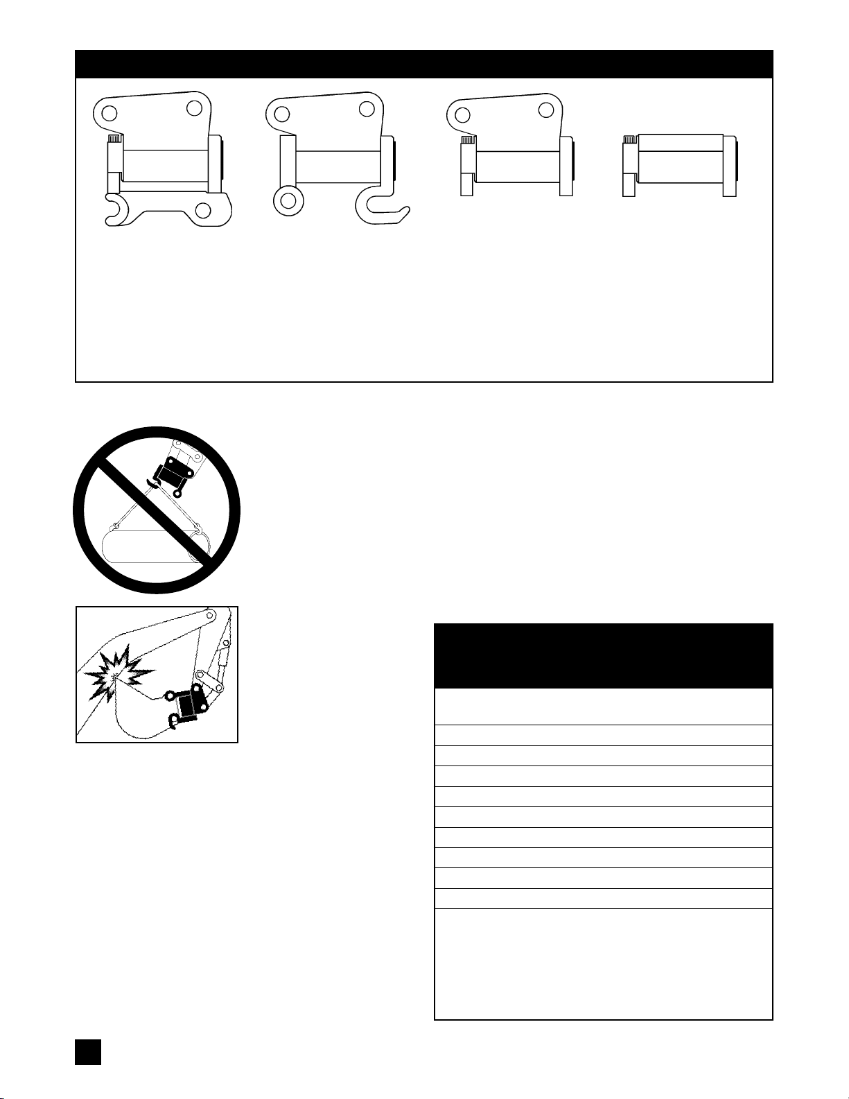
TT SERIES
Integral upper bracket
comes from the factory
readytopinmounttoaspe-
cificcarrier.Thelowershaft
bracketincorporatesahalf-
hitch quick coupler with
hook away from the opera-
tor and is designed to use
the carrier's OEM buckets.
PTB/TBB SERIES
The upper surface is de-
signed with a drilled and
tapped surface to permit
easy bolt-mounting of the
customer's brackets. The
lower shaft brackets are
unfinished.
PT (without coupler)
and TTB SERIES
Integral upper bracket
comes from the factory
ready to pin mount to a
specific carrier.The lower
shaftbrackets areshipped
unfinished to permit cus-
tomization in the field.
BASIC POWER
TILT
CONFIGURATIONS
POWER
TILT
MAXIMUM
MODEL BUCKET WIDTH
05 40" (100 cm)
06 42" (110 cm)
07 48" (120 cm)
08 55" (140 cm)
8.5 60" (150 cm)
09 60" (150 cm)
10 72" (180 cm)
11 75" (190 cm)
12 78" (200 cm)
MAXIMUM RECOMMENDED BUCKETS
FOR USE WITH THE POWER
TILT
FOR
LIGHT DUTY APPLICATIONS*
* Maximum recommended bucket widths above
are intended for light duty applications only.
Applyingthe full bucketcylinder capacitytothe
cornerofawidebucket(i.e.cornerdiggingwith
awidebucket)maycauseprematurewearand/
or reduced equipment life.
PT SERIES
Integral upper bracket
comes from the factory
readytopinmounttoaspe-
cificcarrier.Thelowershaft
bracketincorporatesahalf-
hitch quick coupler with
hook towards the operator
and is designed to use the
carrier's OEM buckets.

5
the end of rotation and then run the
Power
Tilt
circuitoverreliefforoneminute
to completely flush out all hydraulic fluid
and any contaminants which may have
settled in the Power
Tilt.
Reverse the fluid
direction and repeat so that both sides of
thepistonarepurged.Thisprocedurewill
contribute to reduced wear of internal
metalcomponents. The Power
Tilt
cannot
be flushed if the circuit pressure is below
3000 psi
(210 bar)
because the relief
valvesare set toopen between 3000 and
3200 psi
(210 and 220 bar).
Monthly
Check shaft endplay once a month. If endplay ex-
ceeds .015"
(.38 mm),
the end cap must be tight-
ened.
The end cap should not be tightened more
than 1/2 turn total over the life of the thrust
washers.
Tightening beyond1/2turncancausethe
endcaptogalltotheshaftaswellasindicatethatthe
thrust washers (Item 344 and/or 345) should be
replaced.Theendcapcanbetightenedusingeither
of the methods outlined below. For more detailed
instructions, refer to the appropriate sections of the
Disassembly and Reassembly instructions.
Torque wrench With the lockring removed (Item
05), torque the end cap with a torque wrench to the
values specified in the End Cap Torque Specifica-
tionsChartonpage26. If theendplayisbelow.015"
(.38mm),
reassembleandtorqueallfastenerstothe
values specified in Torque Specifications Chart on
page 26.
Hydraulic pressure With the lockring removed
(Item 05), torque by holding the end cap stationary
and hydraulically pressurizing Port P2 to the values
specified in the End Cap Torque Specifications
Chart on page 26. If the endplay is below .015"
(.38
mm),
reassemble and torque all fasteners to the
values specified in Torque Specifications Chart on
page 26.
POWER
TILT
SERIES IDENTIFICATION
There are four basic Power
Tilt
configurations as il-
lustrated on the top of page 4.Though the different
external configurations require slightly different in-
stallation and mounting procedures, all Power
Tilts
are essentially identical internally. The Series can
also be identified by the first two or three charac-
ters of the model number on the ID Tag. Detailed
Assembly Drawings for each Series' can be found
on pages 15-21.
INSTALLATION AND MOUNTING
PT and TT Series Models
EachPower
Tilt
iscustomizedfora specific backhoe
or excavator and is designed to be pin mounted
directly to the machine. Two sets of pins are re-
quired: one set to mount the Power
Tilt
to the
dipperstick,andasecond set tomountthebucketor
attachment to the Power
Tilt
.
Installing the Power
Tilt
onto the carrier
All Power
Tilt
models should be mounted to the
carrier according to the instructions outlined below.
Referring to the illustration above, position the
Power
Tilt
close to the carrier boom to ensure easy
useoftheliftingreachandrangeofthecarrierboom.
Lower the dipper to approximately 2-3" (50-75 mm)
above the Power
Tilt
. Roll out the bucket cylinder to
lowerthelinkbarstothePower
Tilt
.AlignthePower
Tilt
and link bar holes and install the link pin. Slowly lift
the Power
Tilt
to a safe height with the bucket and
boom cylinders. Curl the bucket cylinder until the
Power
Tilt
and dipper holes align and install the
bucket pivot pin.
The above mounting procedure should be com-
pleted without excessive force.
Rotatethepinsasnecessaryandinstalltherequired
retainers.
Do not attach a bucket or attachment to the
Power
Tilt until the hydraulic tool circuit is in-
stalled and operating correctly.
Mounting a bucket
or attachment to the Power
Tilt
Referring to the illustrations appropriate for your
Power
Tilt
modelat thetopofpage6,installthehook
pin in the bucket and position the bucket so the pin
can be easily reached with the Power
Tilt's
hook as
shown. Hook the bucket pin being sure the hook is
properlyalignedtoavoiddamagingthehook.Liftthe
bucketofftheground,thencurlthebucketcylinderto
pivotthePower
Tilt
untilthesecondholeofthebucket
aligns with the Power
Tilt's
coupler pin hole. Install
the second pin and retain properly.
PTANDTTMODELSWITHJACKINGBOLTS:
After
mounting the bucket for the first time, the jacking
bolts(Item 125) onthe back sideof the hookrequire
adjustment. Loosen the jam nut (Item 126) and
thread the bolt until it just contacts the pin, then
tighten the jam nut to lock the bolt in place. Proper
adjustment will make it easier to align the mounting
pins when changing buckets.
TT MODELS ONLY:
If the second pin cannot be
inserted because the Power
Tilt's
shaft bracket and
hook are not correctly aligned, the idler hook (Item
INSTALLING THE POWER
TILT
ONTO THE CARRIER

6
06)mustbeadjusted.Theidlerhookis
clamped in place by the lockring (Item
05). Loosen the lockring cap screws
(Item 120) and position the idler hook
asnecessary.Torquethelockringcap
screws to the values specified in
Torque Specifications Chart on page
26. After both pins are inserted, there
should be a gap of no more than 5/16"
(8 mm) between the hook and its pin.
If this distance is exceeded, please
consult the factory.
Removing a bucket
or attachment from the Power
Tilt
Refer to the illustrations appropriate for
your Power
Tilt
model at the bottom left.
PT MODELS:
With the bucket just
abovethe ground,remove thecoupler
pin (the pin furthest from the cab).
Gently place the bucket on the ground
andmove thePower
Tilt
awayfromthe
bucket to disengage completely, use
the curl cylinder if necessary to make
disengagement easier. Be careful not
to damage the Power
Tilt's
hook.
TT MODELS:
Lift the bucket slightly
and remove the coupler pin (the pin
closesttothecab).Withthebucketjust
contacting the ground, curl the
Power
Tilt
in until the bucket disen-
gages and drops free. Do not curl in
with the bucket on the ground — the
Power
Tilt's
hook can be damaged if
the full force of the curl cylinder is
applied.
PTB, TTB and TBB Series Models
Each PTB, TTB and TBB Series
Power
Tilt
is designed for a specific
backhoe or excavator weight class.
The TTB upper housing brackets are
customizedtopinmountthe Power
Tilt
directly to the dipperstick while the
torque foot (Item 07) and idler foot
(Item06)are designedtobe fittedwith
lower mounting bracket assemblies
specific to the application and/or cus-
tomer. TBB units are designed to be
fittedwithbothupperandlowermount-
ing bracket assemblies specific to the
carrier and/or customer application.
Toassistattachmentdesignersinprop-
erly sizing the mounting brackets and
hardware, Helac can provide an Engi-
neering Design Guide. Contact Helac
Corporation for more information.
Important: The top mounting bracket
must include rotational shaft stops to
prevent the bottoming of the internal
PT SERIES MODELS
TT SERIES MODELS
REMOVING A BUCKET FROM THE POWER
TILT
PT SERIES MODELS
TT SERIES MODELS
MOUNTING A BUCKET ONTO THE POWER
TILT
7
TYPICAL
POWER
TILT
CIRCUIT
(PT Model Shown)
piston.ThePower
Tilt
shouldbemounted on thecarrierwiththetorque foot
(Item 07) oriented towards the carrier.
Forinstructionsonproperbucketandattachment mounting anddismount-
ing,pleaserefertothirdpartybucket/attachment/coupler manufacturer(s).
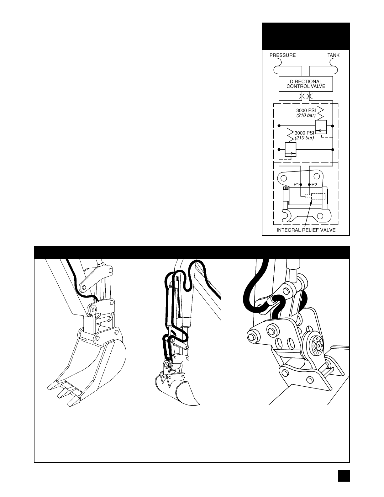
HYDRAULIC REQUIREMENTS AND PLUMBING
The carrier must be fitted with a two-way hydraulic circuit (a typical circuit
schematic is provided to the right). A three position, four way valve is
required to control Power
Tilt
swing. The Power
Tilt
must be protected from
pressures above 3000 PSI (210 bar) by work port or integral cross port
reliefs.AllPower
Tilts
manufacturedsince1997exceptfortheTT-5models
includean integralcross portrelief incorporatedinto theshaft as standard.
Itistheresponsibilityofthedealerand/orcustomertobesurethetool
circuit meets the Power
Tilt
hydraulic requirements.
PT, TT and TTB Series: To assist in easy hose routing, each Power
Tilt
modelis manufactured withfour ports:twoPorts P1and two PortsP2 (see
Assembly Drawings and illustration on page 8). One hose should be
attached to either of the P1 ports and the second hose should be attached
toeitheroftheP2ports.Power
Tilts
deliveredtoNorthAmericancustomers
incorporate SAE port configurations at all four ports; Power
Tilts
delivered
tocustomersoutside of NorthAmericaincorporate either BSPPorJIS port
configurations at all four ports.
PTBandTBB Series: Eachmodelisportedonthetopofthehousing.The
ports consist of one Port P1 and one Port P2 (see Assembly Drawings on
pages 20 and 21). Both ports are BSPP.
AllModels:Thesmallestlinesizeandthemostdirectlineroutingwillresult
in the best possible performance of the Power
Tilt
. Hose and tube size
recommendations can be found in the Tool Circuit Requirements chart at
The hoses are routed along the
sides of the dipperstick, around
the link pins and between the
Power
Tilt
housing brackets.
For extendable dipperstick installa-
tions,be sure thereis sufficient hose
when the dipper is fully extended.
The hoses are clamped to the curl
cylinder, along the link bars, then
under the link bars and between the
Power
Tilt's
housing brackets.
The hoses are routed along the
sides of the dipperstick, looped
andclampedtothelinksorrouted
throughguidesonthelinks,then
routedbetweenthelinkbarsand
the Power
Tilt's
housing brack-
ets.
SUGGESTED HOSE ROUTINGS

8
the bottom of page 8. Use high pressure, braided steel hose and/or steel
tubing which meets or exceeds the hydraulic system's rating.
To minimize the possibility of damage to the hydraulic circuit, it is
recommendedthat lines andhoses berouted usingoneof thesuggested
hoseroutingsillustratedatthebottomofpage7.Becauseeachcarrierand
installation is different, the illustrations are intended as general guides
only. Use the routing that is most appropriate for your installation.
Hoses to the Power
Tilt's
ports should be routed between the housing
brackets and not through the openings in the brackets adjacent to the
ports (these are used for the manufacturing process). Depending on the
geometry of the installation, it may be adviseable to cover the hoses with
protective sheathing.
Connect hydraulic hoses to the appropriate ports using 90° elbow fittings
asseenintheillustrationtotheright.Besurethehosesdonotcross,foul,
crush, or chafe when operating the Power
Tilt
or machine. Verify proper
hoseroutingforallpossiblepositionsofthePower
Tilt
andallattachments
whicharetobeusedwiththePower
Tilt
.Repairany oil leaks immediately.
Ifinstallinganewtoolcircuitornewhydrauliclines
,
flushallthetoolcircuit
lines with hydraulic oil prior to connecting the Power
Tilt.
This will remove
any contaminants from the circuit components which may have accumu-
lated during manufacturing and/or installation.
TOOL CIRCUIT REQUIREMENTS
MODEL 05 06 07 08 8.5 09 10 11 12
DISPLACEMENT
IN317 32 62 89 106 118 159 215 277
cm3278 525 1060 1458 1740 1934 2600 3515 4540
REQUIRED FLOW
GPM .5-1 .8-1.5 1.5-3 3-5 4-6 6-7 6-8 8-11 9-13
Liters/minute 2-4 3-6 6-12 12-20 16-24 24-28 24-32 32-44 36-52
PORT CONNECTIONS
PT/TT/TTB Series - 4 PORTS (2 EACH P1 & 2 EACH P2)*
SAE 6 4 4** 6 6 6 6 6 6
BSPP ¼ ¼ ¼ ¼ ¼ ¼ ¼ ¼ ¼
PTB/TBB Series -2 PORTS (1 EACH P1 & 1 EACH P2)
BSPP ¼ ¼ ¼ ¼ ¼ ¼ ¼ ¼ ¼
HYDRAULIC HOSE & TUBE SIZING
HOSE 3/8"(-6) 3/8"(-6) 3/8"(-6) 3/8"(-6) ½"(-8) ½"(-8) ½"(-8) 5/8"(-10) 5/8"(-10)
TUBE (OPTIONAL) 3/8"(-6) 3/8"(-6) 3/8"(-6) 3/8"(-6) ½"(-8) ½"(-8) ½"(-8) 5/8"(-10) 5/8"(-10)
WHIP HOSE ¼"(-4) ¼"(-4) ¼"(-4) ¼"(-4) ¼"(-4) 3/8"(-6) 3/8"(-6) 3/8"(-6) 3/8"(-6)
(To POWER
TILT)
HYDRAULIC PRESSURES FOR ALL MODELS
OPERATING PRESSURE RANGE 1900-3200 PSI (130-220 bar)
CIRCUIT PRESSURE RANGE 3200-3500 PSI (220-240 bar)
MAXIMUM CIRCUIT BACK PRESSURE*** 600 PSI (40 bar)
* AllPT,TTandTTBSeriesPower
Tilts
manufacturedforNorthAmericancustomersincorporateSAEport
connections. PT, TT and TTB Series Power
Tilts
manufactured for customers outside of North America
and all PTB and TBB Series units incorporate BSPP or JIS port connections.
** Some Model TT-7's incorporate SAE-6 for all ports.
*** Power
Tilts
equipped with factory installed integral cross port relief valves only.

9
TROUBLESHOOTING GUIDE
PROBLEM POSSIBLE CAUSE SOLUTION
Power
Tilt
does not Excessive down pressure This is normal. The integral cross
hold position. applied by excavator causing port relief valve is designed to protect
buildup of pressure in the the Power
Tilt
from excessive internal
Power
Tilt
which is opening pressures that can damage the unit.
the cross port relief valve.
A bi-directional hydraulic Install pilot operated check valves.
motor control valve is being
used without pilot operated
check valves to hold
pressures.
Control valve leaking oil. Test. Repair or replace as needed.
Faulty cross port relief valve. Remove integral cross port relief
valve and visually inspect for
damage or debris. Check pressure
setting of cross port relief valve: non-
adjustable, factory set to open at
2900 to 3200 PSI (197 to 220 bar).
Replace if not within specification.
See Testing and Troubleshooting
on page 10 for testing instructions.
Seals leaking oil. Test. Replace seals as necessary.
See Testing and Troubleshooting
on page 10 for testing instructions.
Power
Tilt
swings in only Single directional control Replace with bi-directional control
one direction. valve is being used. valve.
Cross port relief valve Inspect, test. Replace as needed.
damaged.
Power
Tilt
has spongy Air in Power
Tilt
or Bleed air from circuit.
feel side to side. hydraulic circuit.
Diameter of tubing/hoses Install tubing/hoses with recommended
larger than recommended. diameters.
Install pilot operated check valve in
lines as close as possible to Power
Tilt
.
Forward and backward Worn or missing Tighten end cap (see Maintenance,
movement of shaft in thrust washers. Monthly, page 5). Replace or install
housing (shaft endplay). thrust washers if necessary.
Side to side Some movement is normal Normal movement is 1° to 1½°. If
bucket movement. due to clearance required greater than normal, check shaft
between internal spline endplay; excessive endplay can
teeth. contribute to side to side movement. If
shaft endplay is within acceptable
limits, consult factory.
Power
Tilt
will not accept Grease relief not functioning Clean or replace grease relief valves.
grease at grease fittings. or replaced with grease
fitting or plug.
10
TESTING AND TROUBLESHOOTING
Carrier Hydraulic System Testing
If symptoms of poor performance develop, the chart
on page 9 can be used as a guide. The information
provided is general in nature and does not address
specific applications. When diagnosing faults in
Power
Tilt
operation, it is the responsibility of the
service technician to verify that the carrier and hy-
draulic circuit are operating correctly. Because the
Power
Tilt
receives its power from the carrier, a
thorough check of the carrier hydraulic system is
mandatory before performing any Power
Tilt
service
or adjustments.
Using an accurate flow meter that can operate on a
bi-directional tool circuit, verify correct operation of
the carrier hydraulic system at an operating tem-
perature of at least 80°F (28°C). The flow meter
should be attached first to the hoses that are nor-
mally connected to the Power
Tilt
. In this way, the
entire system from the carrier pump to the Power
Tilt
hoses can be checked for proper performance.
If low performance of the hydraulic system is found,
begin checking upstream of the directional control
valve to verify that the correct input flow and pres-
sureareappliedtothevalve.Iftheflowandpressure
input to the valve are correct, then the problem is in
the valve or the hoses and couplings that lead to the
Power
Tilt
.
Testing the Power
Tilt
Internal leakage
1.Connect a 5000 PSI (350 bar) test gauge into the
line to Port P1. Pressurize until the shaft reaches
theendofrotationandbottomsoutexternally,e.g.
The Power
Tilt
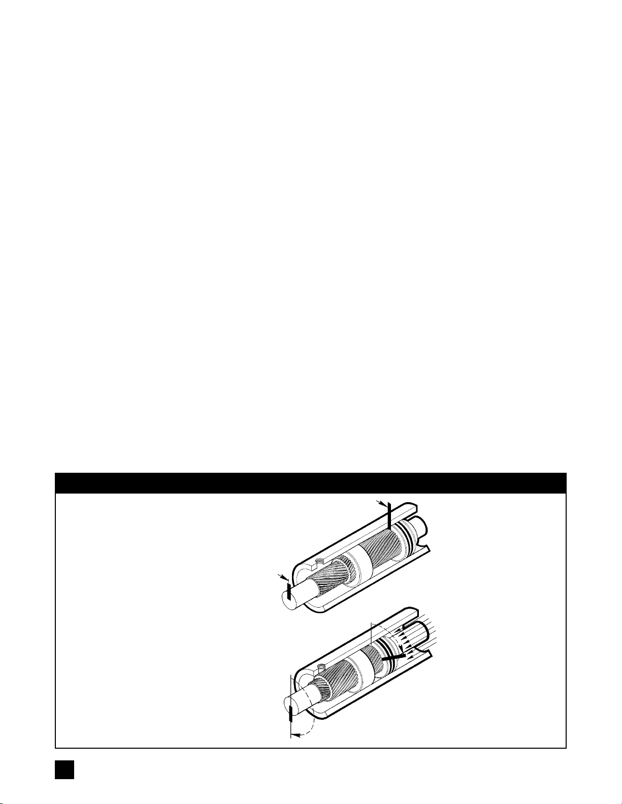
uses Helac's sliding spline
technology which converts linear piston
motion into powerful shaft rotation. The
Power
Tilt
is composed of a housing and
only two moving parts: the central shaft
andtheannularpiston.Helicalsplineteeth
machined on the shaft engage matching
splines on the inside diameter of the pis-
ton. The outside diameter of the piston
carries a second set of splines, of oppo-
site hand, which engage with matching
splinesin thehousing's integralring gear.
As hydraulic pressure powers the piston
back and forth within the housing — simi-
lar to the operation of a hydraulic cylinder
— the splines cause the shaft to rotate.
All working components are protected by
the steel housing. Tough exclusion seals
keep out dirt, water, and other contami-
nants.
Bars indicate starting
positions of piston and
shaft. Arrows indicate
directions they will rotate.
The housing with integral
ring gear remains
stationary. For the sake of
clarity, bearings, end cap,
brackets, couplers, etc.
are not shown.
As fluid pressure is
applied, the piston is
displaced axially while the
helical gearing causes the
simultaneous rotation of
the piston and the shaft.
Helac's unique double
helix design compounds
rotation: shaft rotation is
about twice that of the
piston.
the shaft bracket or torque foot contacts the
housing or mounting bracket. CAUTION: If the
shaft is not completely bottomed out, hydraulic
fluid will exhaust from Port P2 at a high velocity in
Step 2 below.
2.Remove and cap the line to Port P2. Pressurize
Port P1 to 2500 PSI (175 bar). Check for leakage
atPortP2andfromaroundthemainshaftandend
capseals.Leaksindicatewornordamagedparts.
3.Reconnect the hydraulic line to Port P2 and pres-
surize as in Step 1 above.
4.Check for leaks at Port P1 and around the main
shaft and end cap seals, etc. as in Step 2 above.
Cross port relief valve
Theintegralcrossportreliefvalveventshydraulicoil
aroundtheinternalpistonassemblyofthePower
Tilt
at approximately 3000 PSI (210 bar). To test:
1.Connect a 5000 PSI (350 bar) test gauge into the
line to Port P1. Relieve pressure at Port P2 then
remove hose and cap circuit at Port P2.
2.Slowly pressurize Port P1 noting pressure at
which oil flows from P2. The relief should hold
pressureto approximately 2900to 3200 PSI(200
to 220 bar).
3.Test at Port P2 using the same procedure.
The cross port relief valve is set at the factory and
cannot be adjusted. If test pressure does not meet
specification, the valve must be replaced. If piston
seal leakage is suspected, relief port test plugs are
availablefromthefactory.NOTE:TT-5andTT/TTB/
TBB-8.5modelsdonotincorporateanintegralcross
port relief valve.
OPERATING CONCEPT
11
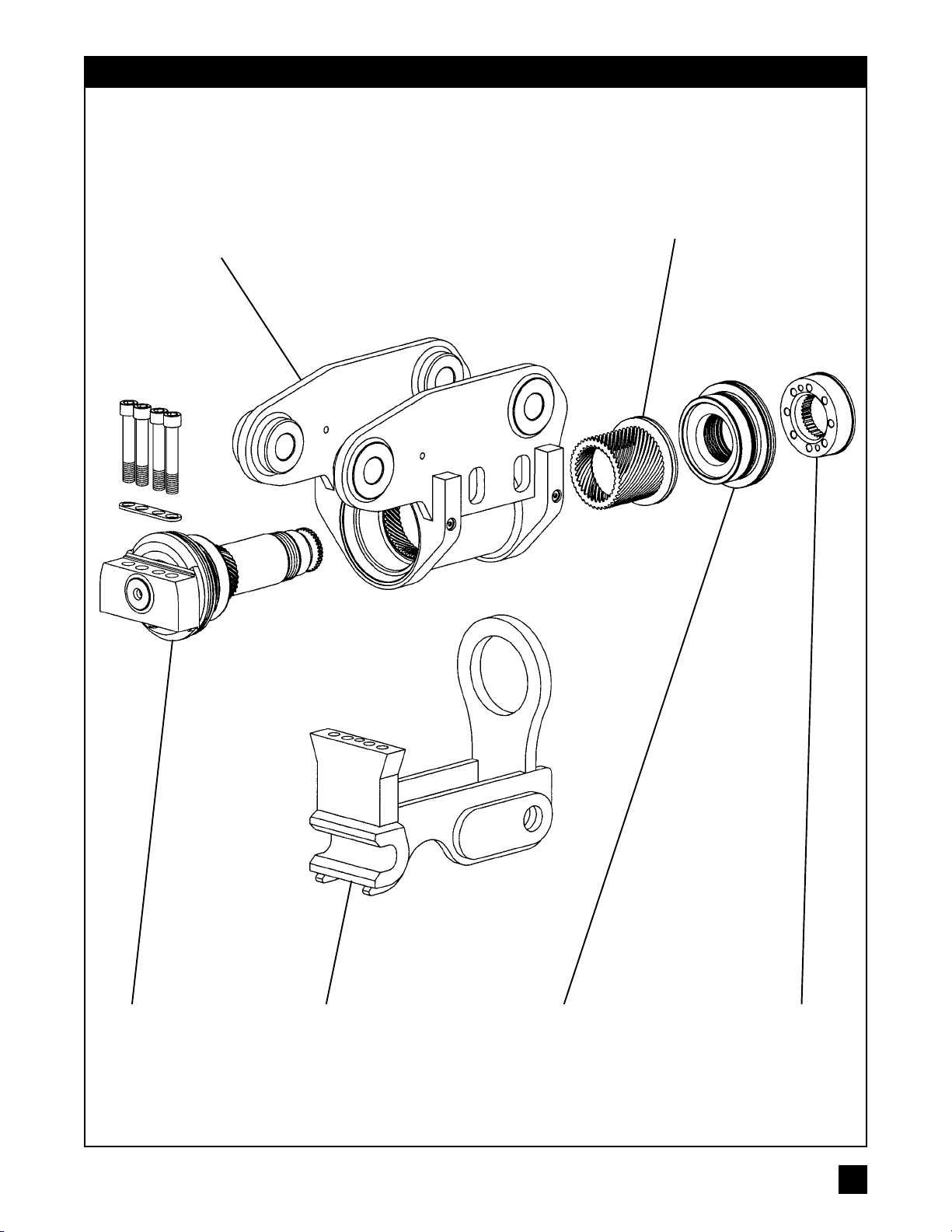
EXPLODED VIEW
PT SERIES MODELS
END CAP
WITH BEARINGS
PISTON
SLEEVE
SHAFT
HOUSING WITH
INTEGRATED
RING GEAR
LOCKRINGSUBFRAME
COUPLER

PHOTO A
PHOTO B
12
DISASSEMBLY
Note: Metric fasteners are used throughout.
1. Removeallhydraulicfittings.PlacethePower
Tilt
onacleanworkbench
with ample room to place the internal parts as they are removed.
2. PT/PTB/TTB/TBB Series - Subframe coupler removal
1) Unthread and remove the torque foot mounting screws (104).
2) Unthread and remove the lockring screws (120) and the lockring
set screws (129).
3) Thread two lockring screws (120) into two diagonally opposed
threaded holes in the lockring (05). Advance the screws equally a
littleatatimeinordertojackthelockringofftheshaft(02)andidler
foot (06).
4) PTSERIESLiftthehousingassemblyoutofthesubframecoupler
(09).Notethereisanalignmentdowelpin(105)betweentheshaft
and subframe coupler. Remove the lockring O-ring (239).
PTB/TTB/TBB SERIES Lift the housing assembly out of the idler
foot (06), torque foot (07) and any associated buckets, attach-
ments, and/or other lower assemblies. Note there is an alignment
dowel pin (105) between the shaft and torque foot.
5) Place the housing assembly on a clean, level work surface.
TT Series - Half-hitch coupler removal
1) Unthread and remove the lockring screws (120) and the lockring
set screws (129).
2) Remove the lockring (05), then the idler hook (06). If the lockring
is difficult to remove, thread two lockring screws (120) into two
diagonally opposed threaded holes in the lockring (05). Advance
the screws equally a little at a time in order to jack the lockring off
the shaft (02) and idler hook (06).
3) Place the housing assembly on a clean, level work surface.
3. Unthread the port plug (101) and remove the cross port relief valve
(413).NOTE:TT-05andTT/TTB/TBB-8.5modelsdonotincorporate
an integral cross port relief valve.
4. Unthread the end cap (04) from the shaft (02) and remove the thrust
washer(344). A considerableamount ofoilmay flowout the housing
when the end cap is removed.
5. Rotate the shaft to slide out of engagement with the piston sleeve
assembly(03).Aconsiderableamountofoilmayflowoutthehousing
when the shaft is removed. Note the orientation between the spline
teeth on the piston sleeve and shaft: small punch marks on the face
ofthesplinedpistonsleeveandtherootofashaftsplinetoothindicate
timing. See Photo A. Correct orientation will assure proper timing
during reassembly. Remove the thrust washer (344 or 345). For PT
andTTSeriesmodels,removetheshaftbracketbushings(116) only
if they exhibit excessive wear.
6. Rotate the piston sleeve assembly (03) out of engagement with the
housing(01).Greatcareshouldbetakentoinsurethatthegearteeth
are not damaged and the housing bore is not scratched when the
piston is removed. Support the piston as it clears the housing to
prevent damage. If seal friction makes it difficult to move the piston,
use a rubber mallet and hard rubber bar as seen in Photo B.
For Models 08, and larger, it is easier to position the Power
Tilt
vertically to remove the piston as seen in Photo C.
7. Depending on the model, the piston sleeve may be a one-piece or
two-pieceassembly. The two-pieceassembly consistsof aseparate
piston and sleeve that are threaded together and cross pinned.
The
piston sleeve does not need to be disassembled unless the O-
ring (232) is suspected of leaking.
To disassemble Models 08/10/
11/12removethepistonbearing(343).ForModels07/8.5/09remove
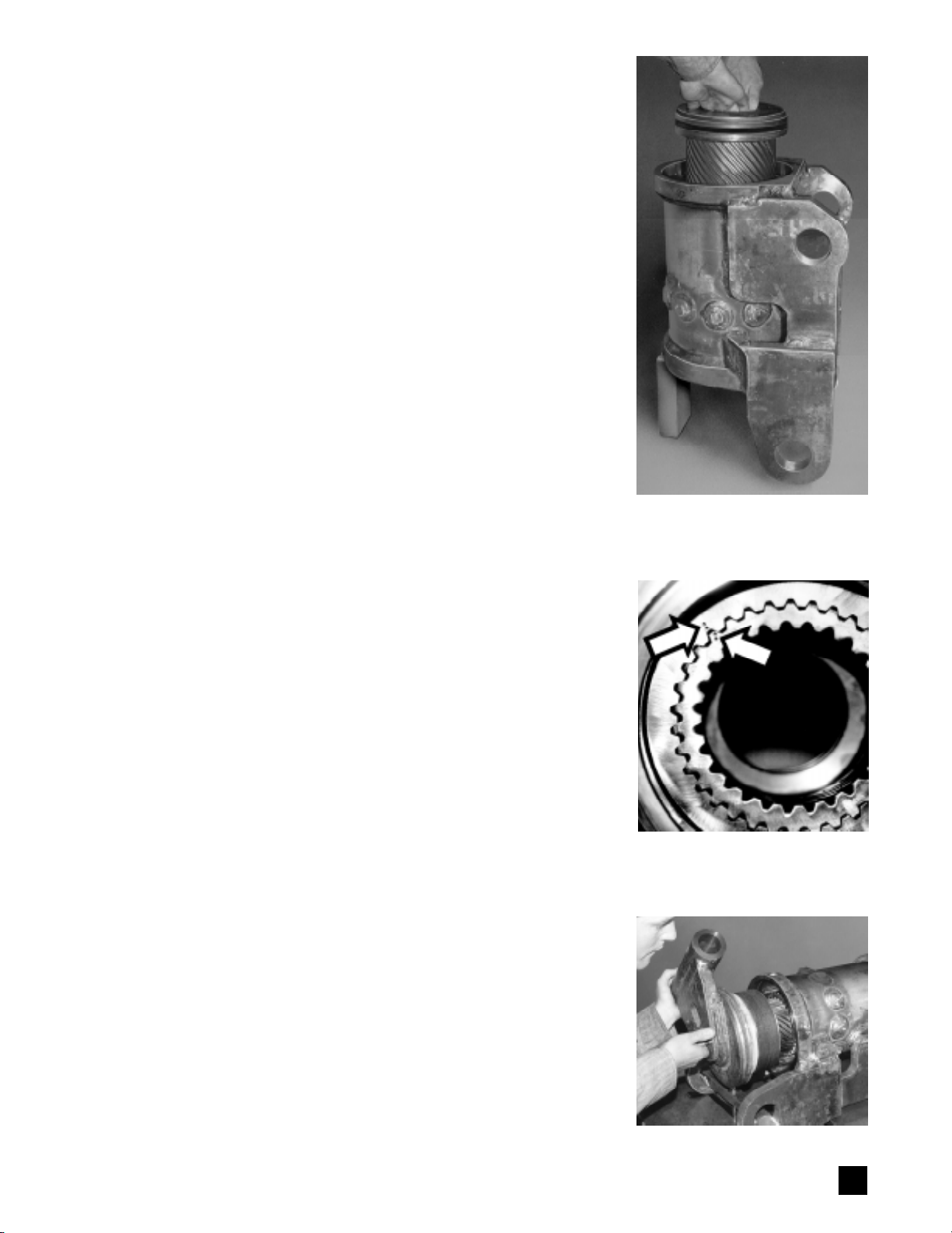
PHOTO E
PHOTO D
PHOTO C
13
the cross pin retainer (127), either a wire or an O-ring, depending on
the model. If necessary, remove the cross pins (121) and unthread
the piston and sleeve.
8. Remove the grease fittings (122), grease relief covers (107), and
grease reliefs (123).
9. Remove all seals and bearings from their grooves — note orienta-
tions of seal lips prior to removal.
10. Cleanallcomponentsthoroughlywithsolventorinapartswasher. Be
sure to flush all grease and contaminants from grease fitting and
grease relief passages.
PARTS INSPECTION
1. Inspect all parts for wear, damage, cracks, etc.
Housing Inspect the cylinder bore for wear and scratches. The
surface finish should be 32 RMS or better. If the bore requires
rehoning, return the housing to Helac Corporation for rehoning.
Inspectallbearingcontactsurfacesfordamageand/orcontamination
andrepairandcleanasnecessary.Inspecttheexteriorofthehousing
for damage, cracks, integrity of welds, etc.
Bearings Allradialbearings areofa glass-reinforced nylonmaterial.
If the thickness measures less than .123" (3.125 mm), the bearings
should be replaced.
Thrust washers If the thickness measures less than .105" (2.65
mm), the thrust washers should be replaced.
Seal grooves Inspect for damage.
Shaft, end cap, idler hook, and subframe coupler Rough and
groovedbearingjournalsrequirereplacementoftheshaftand/orend
cap. Be sure end cap threads are clean and without burrs. Inspect
external parts for damage, integrity of welds, excessively worn shaft
bracket bushings, etc.
REASSEMBLY
Itisrecommendedthatyoufirstpracticeassemblingthe
Power
Tiltwith
thebearings installed but withoutseals. The sealsare easily damaged
and their increased friction makes assembly more difficult. All seals
must be replaced whenever the
Power
Tilt is reassembled. The thrust
washersshouldbecheckfitpriortoinstallation.Handlethrustwashers
carefullytopreventdamage.Tighten all fasteners to torques specified
in the Torque Specifications chart on page 26.
1. Wash all parts thoroughly, blow dry, and protect from corrosion.
2. Install grease fittings (122), grease reliefs (123), and grease relief
covers (107). Pump a high quality NLGI-2 lithium based grease into
the grease fittings (122) to flush any contaminants out of the fittings
and passages and to insure the fittings are functioning properly.
Replace any nonfunctioning fittings. Wipe off all excess grease.
3. Lightly coat all sealing and working surfaces with a good grade of
hydraulic oil.
4. One piece piston sleeves Install seals (234) (235) on the piston
sleeve (03). Install bearing (342).
Two piece piston sleeves
(Some Models 07, all Models 08 through
12):
InstallO-ring(232)andback-uprings(233)onthepiston.Thread
pistonandsleevetogetheruntilcrosspinholesalign.Insertcrosspins
(121). For Models 07, 8.5 and 09 install the cross pin retainer (127),
either a wire or an O-ring, depending on model. Install seals (234)
(235) on the piston sleeve assembly with the lips oriented as seen in
theDetailDrawings onpages22 and 23.Installbearings (342)(343).
Note: Models 06, 07, 08, 09 and 11 have only one seal each on the ID
and OD of the piston sleeve. Models 8.5, 10 and 12 require one each

P2tothevaluesspecifiedintheEndCapTorque
Specifications chart on page 26.
13. PT/PTB/TTB/TBB Series
Subframe coupler installation
1) Insert the shaft dowel pin (105) into the shaft (02).
2) Check fit the alignment of the lockring (05)
and end cap (04) by threading the lockring
screws (120) into the end cap. If the holes do
not align, thread the end cap in or out slightly
as necessary. After alignment is confirmed,
remove the lockring and cap screws.
NOTE:
Do not rotate the shaft with the lockring re-
moved after torquing the end cap.
3) Coat the exposed diameter of the shaft,
lockring splines (05), and interior surfaces of
PT model subframe coupler (09) and PTB/
TTB/TBB model idler foot (06) with grease.
4) PT SERIES Install the housing/shaft assem-
bly
into the subframe coupler (09).
PTB/TTB/TBB SERIES Install the top mounting
brackets(PTB/TBBSeriesonly).Installthehous-
ing/shaft assembly
into the lower mounting
bracketassemblywhichincludesthetorquefoot
(07), idler foot (06), and any associated lower
buckets,attachments,and/orotherassemblies.
5) Install the lockring (05). Install the lockring
screws (120) and lockring set screws (129).
Install the washer plate (106) and the shaft
mounting screws (104). Torque all fasteners
asspecifiedintheTorqueSpecificationschart
on page 26.
TT Series
Half-hitch coupler installation
1) Check fit the alignment of the lockring (05)
and end cap (04) by threading the lockring
screws (120) into the end cap. If the holes do
not align, thread the end cap in or out slightly
as necessary. After alignment is confirmed,
remove the lockring and cap screws.
NOTE:
Do not rotate the shaft with the lockring re-
moved after torquing the end cap.
2) Coat the exposed diameter of the shaft, interior
surfaces of the idler hook (06) and lockring
splines (05) with grease.
3) Installtheidlerhookandtimewiththefrontshaftbracket.
4) Install the lockring (05). Install the lockring
screws (120) and lockring set screws (129).
Torqueall fastenersto the values specified in
the Torque Specifications chart on page 26.
5) Install the shaft bracket bushings (116) if necessary.
14. Grease the thrust washers. Pump a high quality
NLGI-2 lithium based grease into the grease
fittings (122) at both ends of the housing until it
exhausts from the grease reliefs (123).
15. Install hydraulic fittings.
NOTE: The
Power
Tilt should be operated with-
outaloadforonetotwominutes,thenregreased
before going into service. Do not operate
the
Power
Tilt with the lockring removed.
seals (204) and (205) with the O-ring energizers
removedfromthesealsnearestthepistongearing.
5. Apply a thin coat of grease to all piston sleeve
seals, then install the piston sleeve in timed
relation to the housing ring gear. For Models 08
andlarger,itiseasiertoinstallthepistonwiththe
housingpositionedvertically as demonstrated in
Photo C. Time the piston by aligning the punch
marks on the gear faces as seen in Photo D.
Apply firm pressure as the new seals and bear-
ingsenterthehousing and becomecompressed
by the housing chamber; use a rubber mallet if
necessary.Pushthe piston into thehousinguntil
it bottoms out against the housing ring gear.
6. Position the housing horizontally. ForTT-05,TT/
TTB/TBB-06, and TT/TTB/TBB-07 single collar
designs, install the front thrust washer (345) in the
housing. For all other models (two collar designs),
install the front thrust washer (344) on the shaft.
Note: Thrust washers should be installed dry.
Install seals (236 or 237) (238) and bearing (340) on
the shaft (02). Some models have multiple bearing
strips; fill the groove completely with bearing strips.
7. Applyathinfilmofgreasetotheshaftseals,then
install the shaft as seen in Photo E in timed
relation to the piston sleeve by aligning the
punched timing marks as seen in Photo A. Tem-
porarily taping the threaded portion of the shaft
withmaskingtape can make iteasiertoclearthe
piston sleeve seals. Rotate the shaft until it is
completely bottomed out in the housing.
8. Remove the tape from the shaft threads and
apply anti-seize thread lubricant to the threaded
and surrounding areas of the shaft.
9. Install the thrust washer (344) on the end cap.
Note: Thrust washers should be installed dry.
10. Install seals (230) (231) (237) (238) and bearing
(340) on the end cap (04). See Detail Drawings
onpages22 and23for correct sealorientations.
Apply a thin film of grease to the seals, then
thread the end cap onto the shaft to a net fit
where the end cap just begins to clamp against
the thrust washer. For PT and PTB Series mod-
els, install the lockring O-ring on the shaft.
11. Install the relief valve O-ring (201), valve back-
upring(202),andvalveportO-ring(203).Thread
thecrossportreliefvalve(413)intotheshaftand
install the port plug (101). Note Models 05 and
8.5 do not incorporate a cross port relief valve.
12. Torque the end cap using either of the methods
outlined below when new thrust washers are
beinginstalledorwhenthrustwashersarewithin
tolerance specified.
Torque wrench Torque the end cap with a
torque wrench to the values specified in the End
Cap Torque Specifications chart on page 26.
Hydraulic pressure Torque by holding the end
capstationaryandhydraulicallypressurizingPort
14

PT SERIES ASSEMBLY DRAWING
Models PT-06 through PT-12
Configurations of parts may differ between models
15
ORIENTATION TOWARDS EXCAVATOR/CARRIER WHEN INSTALLED
➔

16
TT SERIES ASSEMBLY DRAWING
SINGLE COLLAR DESIGNS* — Models TT-05 through TT-07
Configurations of parts may differ between models
ORIENTATION TOWARDS EXCAVATOR/CARRIER WHEN INSTALLED
➨➨
➨➨
➨
➔

17
TT SERIES ASSEMBLY DRAWING
TWO COLLAR DESIGNS* — Models TT-06 through TT-12
Configurations of parts may differ between models.
ORIENTATION TOWARDS EXCAVATOR/CARRIER WHEN INSTALLED
➔

18
TTB SERIES ASSEMBLY DRAWING
SINGLE COLLAR DESIGNS* — Models TTB-06 and TTB-07
Configurations of parts may differ between models
ORIENTATION TOWARDS EXCAVATOR/CARRIER WHEN INSTALLED
➔

19
PT AND TTB SERIES ASSEMBLY DRAWING
TWO COLLAR DESIGNS* — Models PT/TTB-06 through PT/TTB-12
Configurations of parts may differ between models
ORIENTATION TOWARDS EXCAVATOR/CARRIER WHEN INSTALLED
➔

20
TBB SERIES ASSEMBLY DRAWING
SINGLE COLLAR DESIGNS* — Models TBB-06 and TBB-07
Configurations of parts may differ between models
ORIENTATION TOWARDS EXCAVATOR/CARRIER WHEN INSTALLED
➔
This manual suits for next models
4
Table of contents
Popular Construction Equipment manuals by other brands

Altrad
Altrad BELLE TDX 650A Operator's manual

Saferoad
Saferoad VR Arcus Primus 90 Series Installation instruction

UTIFORM
UTIFORM V1 Instruction book

Saferoad
Saferoad VR Arcus Primus 90 Assembly Drawing

Metabo HPT
Metabo HPT VB 3616DA manual

Trejon
Trejon MULTIFOREST V Series Instruction Manual and Maintenance Directions

Dural
Dural Z-FLEX CURVER I operating instructions

E-Z DRILL
E-Z DRILL 210-3 EQ MT maintenance

BE Ag & Industrial
BE Ag & Industrial AGRI EASE DIAMOND HARROW HAR60S Assembly instructions

SPIERINGS
SPIERINGS SK597-AT4 manual

Labounty
Labounty CP 80 Safety, operation & maintenance manual

hymer
hymer 6071 Instructions for use


