HELGI VIDEO MOTORE PROJECTION SCREEN Instructions for use
Helgi Europe
Via Artigiani 29/31 29020 Vigolzone (PC) Italy
education@helgi-solutions.com | business@helgi-solutions.com
www.helgi-solutions.com
1
INSTRUCTION AND MAINTENANCE
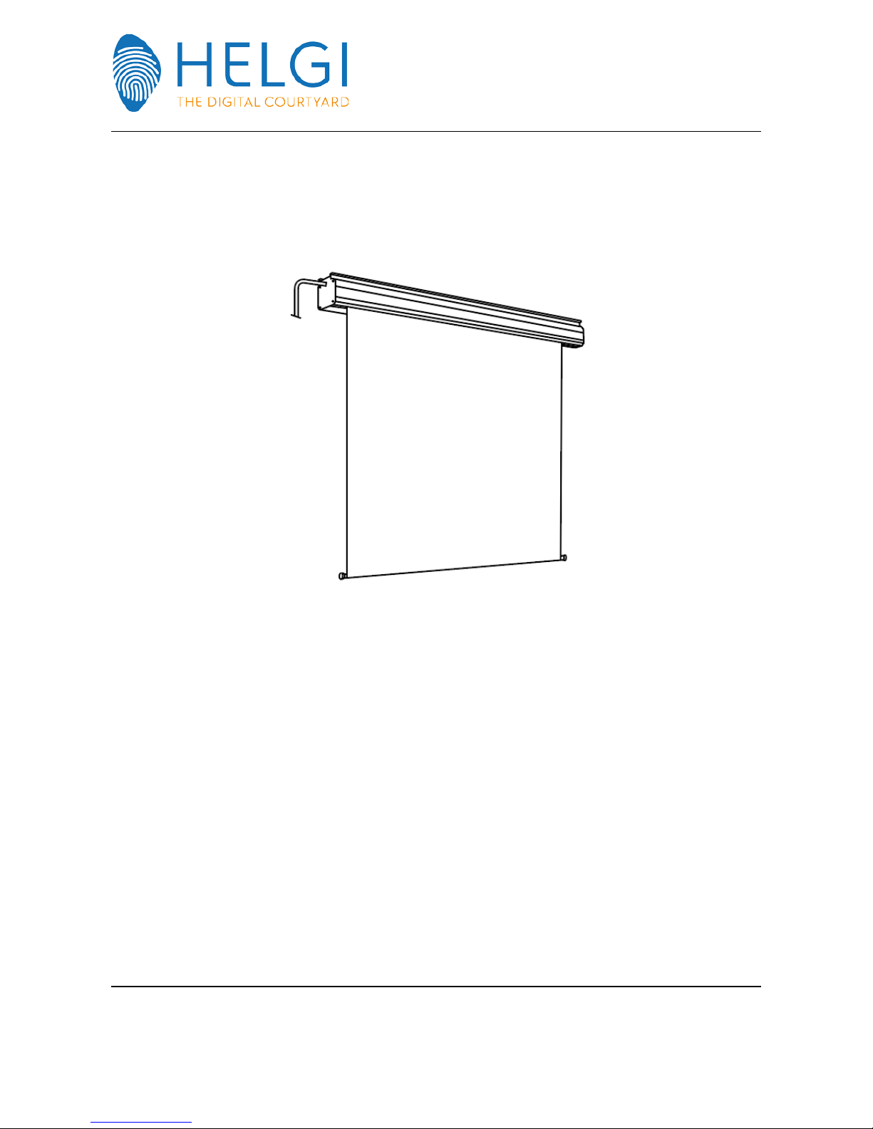
VIDEO MOTORE PROJECTION SCREEN
1.1 TECHNICAL DATA
PRODUCT DESCRIPTION
Screens made with the following projection fabrics: SOFT WHITE, MATT WHITE SOFT, SOFT WHITE TRANSOUND, RETRO
(see technical pages 5/6/7) – In the standard version, the screen is lowered from the front side of the box, by wall
installation the fabric will descend at a distance from the same of mm 81.5 to 97.5, on request, the screen can be
provided with rear lowering system, in this case the fabric will be at a wall distance of approximately 22.5 to 16.5 mm -
Screen case of extruded aluminium, powder coated in white RAL 9010, section 85x93 mm with rounded corners on the
upper ribs suitable for the fixation of hooking brackets; on the bottom part longitudinal slot with rounded edges,
through which the projection fabric descends, – Internal tube for the screen rewinding, of anodized aluminium silver Ø
60 mm, which incorporates the electric motor on special silent-block rubber – Single phase electric motor, IMQ, CE, 5-
year warranty from date of purchase, supply 200V - 50Hz, 0.5 A absorption, degree of protection IP 44, 17 RPM, in the
standard version the motor is mounted on the left side – screen up and down electric inverter standard supplied. Screen
up and down limit switches factory adjusted, possibility of different settings if necessary. The screen can also be stopped
at intermediate height by pressing the electric inverter switch - Suspension brackets are standard supplied and can be
mounted anywhere along the whole housing length. Brackets are steel made, epoxy powder coated in white RAL 9010,
suitable both for wall or ceiling installation thanks specific expansion anchors - Screen case end caps steel epoxy coated
in white RAL 9010 – Robust individual packing in double cardboard type Volcano - Product CE certified, full warranty 24
months as specified on the operating and maintenance manual- Optional accessories: radio remote control, spacing
brackets - Box dimensions: size of the base of the canvas +7 cm

Helgi Europe
Via Artigiani 29/31 29020 Vigolzone (PC) Italy
education@helgi-solutions.com | business@helgi-solutions.com
www.helgi-solutions.com
2
1.1.1 ELECTRIC CONTROL MOTOR SINGLE PHASE
•Standard voltage 230 V - 50 HZNormal power 120 W
•Power consumption 0.5 A
•Degree of protection IP 44
•17 rpm
•Normal torque 6 Nm
•Approval "IMQ"
1.1.2 ELECTRIC UP-DOWN INVERTER 10 A
•Section output engine cables N. 4 x 1,5mq
•Power supply cable PHASE + NEUTRAL + EARTH sect. 1,5 mm
•POWER SUPPLY 220 VOLT - 50 HERTZ
1.1.3 REMOTE CONTROL (if any)
•Operating frequency: 433.920 Mhz
•Coding System: self code learning
•N. of codes to be memorized: 1000 for each receiver
•Capacity (BROWN) Impedance 50 Ohm
•Receipt range capacity: 40 m ca. (Please note that the value is to be considered guidance and can be
influenced by barriers, metal structures, electromagnetic fields etc.).
-Supply voltage 230 V aprox.
-Power consumption 1.5 W MAX
-Operating temperature - 10 ° to + 55 ° C
Helgi Europe
Via Artigiani 29/31 29020 Vigolzone (PC) Italy
education@helgi-solutions.com | business@helgi-solutions.com
www.helgi-solutions.com
3
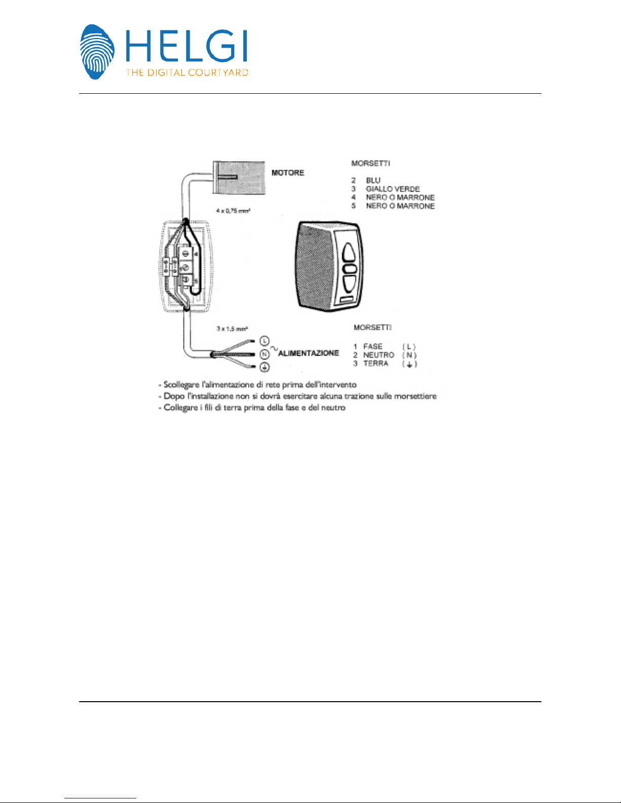
1.1.4 ELECTRICAL WIRING DIAGRAM FOR INVERTER SWITCH
MOTORE = MOTOR POWER | MORSETTI = WIRING TERMINALS
2 BLUE
3 YELLOW GREEN
4 BLACK OR BROWN
5 BLACK OR BROWN
1 PHASE
2 NEUTRAL
3 GROUND
-Disconnect mains power prior to any operation
-After installation you should not operate any traction on the terminals
-Connect the grounding wires before the phase and neutral

Helgi Europe
Via Artigiani 29/31 29020 Vigolzone (PC) Italy
education@helgi-solutions.com | business@helgi-solutions.com
www.helgi-solutions.com
4
1.1.5 WIRING FOR REMOTE CONTROL
To install the unit, proceed as follows:
a) prepare the Jumper
b) connect the power supply and the motor (with the limit switches)
c) if required, connect the manual wall switches open/close
Helgi Europe
Via Artigiani 29/31 29020 Vigolzone (PC) Italy
education@helgi-solutions.com | business@helgi-solutions.com
www.helgi-solutions.com
5
1.2 PROJECTION FABRIC
PVC projection fabric, thickness 400 MY, height. 2400, cadmium free, type fire proof class M1, as per french
definition and in compliance with EEC 91/338. Light white colour with a smooth side, rear of the screen not
to be used and a satin finish side for projections.
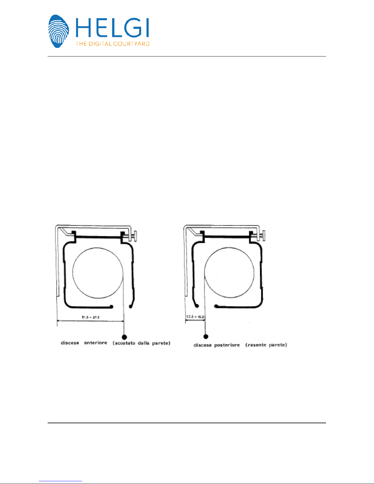
In the standard version, front screen lowering from the screen case, consequently wall distance about mm.
81.5 - 97.5 in the case of wall fixation, on request, it can be supplied with rear lowering system , in this case
wall distance will be mm. 22.5 to 16.5.
The projection canvas is rolled on a silver anodized round aluminium tube, section dia.mm.60, which
integrates the electric motor.
For best viewing, it is recommended to unroll the screen at least few hours before projection start to allow
the canvas to perform its best planarity.
FRONT LOWERING (WALL DISPLACED) REAR LOWERING (CLOSE TO THE WALL)

Helgi Europe
Via Artigiani 29/31 29020 Vigolzone (PC) Italy
education@helgi-solutions.com | business@helgi-solutions.com
www.helgi-solutions.com
6
1.3 ALUMINIUM CASE
Extruded aluminium casing powder coated in light grey RAL 7035, section mm. 85x93 with rounded corners,
upper ribs with appropriate hooking brackets, longitudinal slot with rounded edges , through which the
projection canvas is lowered, on the bottom left side of the screen case, two holes enable the access to the
canvas raising/lowering adjustment screws.
2.0 SAFETY
2.1 SAFETY CRITERIA ADOPTED
The cables supplied are contained in a single housing of self-extinguishing plastic, however, wall or ceiling
mounting must comply with the law 46/90 and be conducted by appropriate staff.
In case of failure of one of the two limit adjustment screws, on the electric motor, there is a thermal switch
capable to open the electrical circuit.
The whole equipment was designed for maximum safety.
2.2 SAFETY COMPONENTS
The adopted safety components are:
•Robust suspension brackets widely oversized
•thermal electric switch in case of failure of one of the two limits.
•No sharp corners or sharp edges which could cause injury
Helgi Europe
Via Artigiani 29/31 29020 Vigolzone (PC) Italy
education@helgi-solutions.com | business@helgi-solutions.com
www.helgi-solutions.com
7
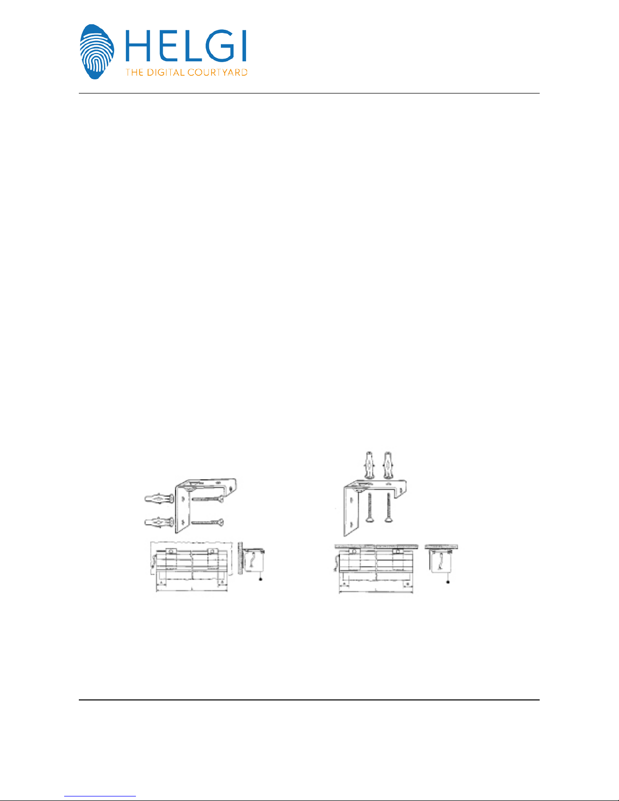
3.0 INSTALLATION
The installation of this type of screens can be to wall or to the ceiling.
3.1 INSTALLATION INSTRUCTION
To make a correct installation, position the two suspension brackets in such a way that the screen is
suspended about 1 / 15 of its length, measured from one of the two terminal heads.
Fix the brackets to obtain an alignment as accurate as possible.
Use reliable anchors and appropriate to the wall, minimum recommended size diameter mm. 8.
IMPORTANT! Make sure that wall or ceiling are appropriate to support the declared weight and to the
installation through screw anchors.
When in doubt, use chemical fixings type . Once brackets are fixed, lift up the screen and attach it on the
appropriate tab of the bracket, then slightly tighten the front screw and tighten the lock bolt.
This must be done by two people, one from the left side, the other from the right side.
IMPORTANT! Choose walls with a flat surface, otherwise the bracket tag will not ensure the suspension of
the screen.

Helgi Europe
Via Artigiani 29/31 29020 Vigolzone (PC) Italy
education@helgi-solutions.com | business@helgi-solutions.com
www.helgi-solutions.com
8
4.0 OPERATION
4.1 GENERAL DESCRIPTION
After the electrical connections, make sure of the exact voltage of the power supply, close the circuit and
giving power and operate with short pulses on the inverter "Lowering." Make sure everything runs properly
and then operate few times the up/down mechanism. At this point the operation was well performed.
5.0 USE
5.1 SETTING THE LIMIT SWITCHES
The only adjustment to be made is that of the two up and down switches up of the projection screen. These
two elements are already set during production, by the manufacturer.
However, you can make some adjustments by turning the two limit switches screws, which can be reached
by introducing a 4 mm hexagonal key – standard supplied - in the two holes on the bottom of the screen
case.
IMPORTANT! Do not unroll the canvas over the measurement specified for each type of screen: increasing
the descent above this size could damage the screen or cause its fall off, such damages are not covered by
warranty and are not under the responsibility of the manufacturer.
Likewise, do not force the rewinding of the canvas after it has been completely rolled up as this would force
the electric motor and the counter weight tube could get stacked into the box and consequently get
damaged.

Helgi Europe
Via Artigiani 29/31 29020 Vigolzone (PC) Italy
education@helgi-solutions.com | business@helgi-solutions.com
www.helgi-solutions.com
9
Setting the upper limit switch
-Bring the canvas to the maximum upper position, then stop the movement by pressing STOP
button (centre position)
-Insert the 4 mm hexagonal screw (standard supplied) in the 1st hole near the opening of the
descent of the canvas, turn the screw counter-clockwise = more winding-up, clockwise = less
winding-up.
•Each turn of the screw is approximately mm. 35 displacement of the canvas.
•Setting the lower limit switch
-Bring the canvas to the maximum lower position, then stop the movement by pressing
•STOP button (centre position)
-Insert the 4 mm hexagonal screw (standard supplied) in the 2nd hole (the farthest one from
the canvas), turn the screw counter-clockwise = more descent, clockwise = less descent.
DISCESA = DOWN SALITA = UP | LATO PROIEZIONE = PROJECTION SIDE

Helgi Europe
Via Artigiani 29/31 29020 Vigolzone (PC) Italy
education@helgi-solutions.com | business@helgi-solutions.com
www.helgi-solutions.com
10
5.2 RECOMMENDATIONS AND PROHIBITION
It is forbidden the use of the screen by persons below 16 years of age or disabled or otherwise altered in
their operational ability.
It also prohibited the installation on precarious, unstable and uneven walls. Environments with high humidity,
dusty, in the presence of explosive mixtures. It is not recommended the screen continue exposure to sunlight,
which could alter the original colour of the canvas.
Do not expose the screen to temperatures above 50 ° C, this could cause irreparable damages.
In case of malfunction of the motor, do not force manually the output of the canvas, but call service.
Do not adjust the limit switches continuously and without any real necessity.
Table of contents
Other HELGI Projection Screen manuals


Popular Projection Screen manuals by other brands


Recordex
Recordex Motorized Electric Projection Screen user manual

Costway
Costway OP70571 user manual

Da-Lite
Da-Lite MULTI-MASK IMAGER Instruction book

Nierbo
Nierbo E46399F9FF instructions

Screen Research
Screen Research TheaterCurved Reference X-Mask T-XLR3 installation manual

SCREENLINE
SCREENLINE New Only White manual

Draper
Draper Envoy Installation & operating instructions

Draper
Draper Salara installation instructions

Severtson
Severtson TF43 Series instruction manual

Elite Screens
Elite Screens F60XWV1 user guide

Da-Lite
Da-Lite PERM WALL FRAME installation instructions
 Series user guide")
Elite Screens
Elite Screens VMAX2 (Plus) Series user guide