Helio MAP 50 User manual

HGD G4CH VER. 1.1 1
A
www.helioGD.com
www.helioGD.com
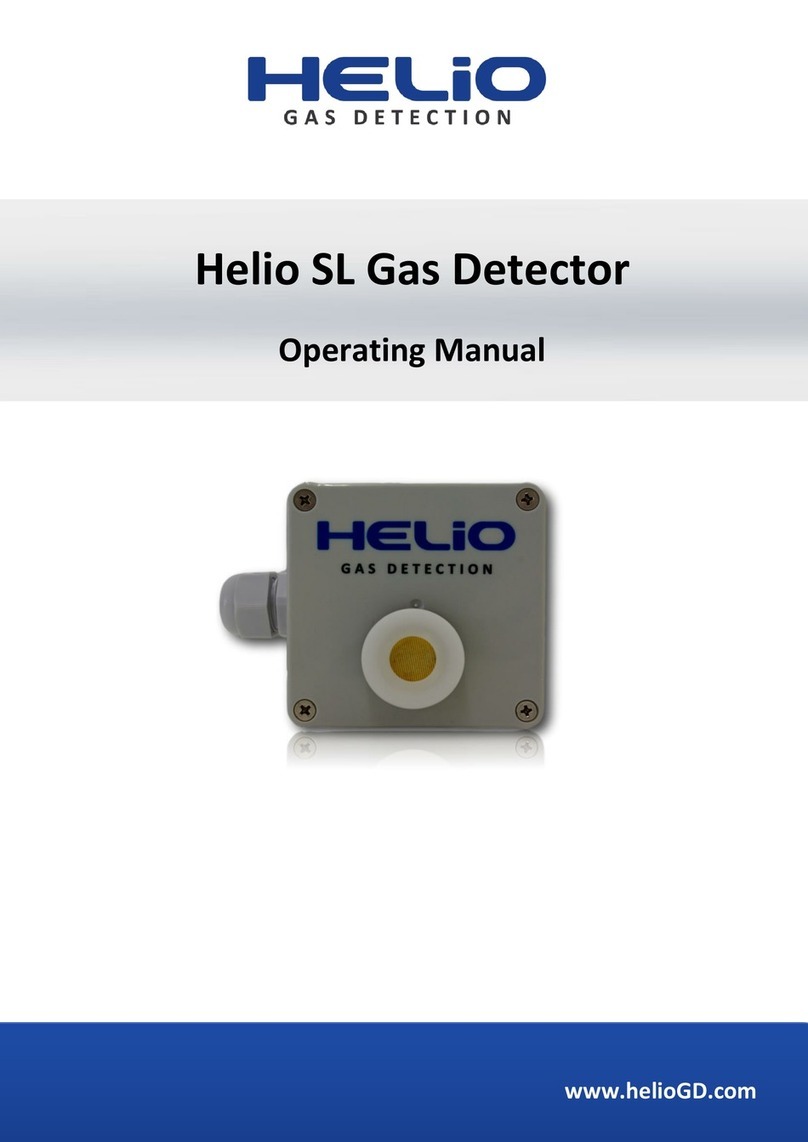
Helio MAP 50
Operating Manual

HGD G4CH VER. 1.1 2
Please read and understand the contents of this manual before commencing
installation!
Contents
Important Remarks Page 4
Warranty
Intended Use
Technical Specifications Page 5
Environmental Specifications
Electrical Specifications
Sensor Specifications
Internal Wiring Page 6
Start-up Page 6
Maintenance Page 7
Sensor Replacement Page 7
Detector Overview Page 8
Menu Structure Overview Page 9
Menu Structure Overview (continued) Page 10
First Time Setup
Set Number of Channels Page 11
Set Channel Input Type Page 11
Set Channel Gas Species Page 11
Main Menu Selection Screen
How to Access Main Programming Menu Page 12
General Settings
Set Time Page 13
Set Address Page 13
Set Password Page 13
Set Channel Zone Page 14
Factory Default Page 14
Isolate Detector Page 14

HGD G4CH VER. 1.1 3
Contents
Analog Output Menu
Simulate mA Page 15
Adjust mA Offset Page 16
Adjust mA Span Page 16
Alarm Level Menu
Configure Channel Page 17
Alarm 1 Direction Page 17
Alarm 1 Level Page 18
Alarm 1 Reset Level Page 18
Alarm 2 Page 18
Relay Configuration Menu
Choose Relay Page 19
Relay Functiom Page 19
Alarm Latching Page 19
Relay State Page 20
Alarm Delay Page 20
Test Relay Page 21
Calibration Menu
Zero Calibration Page 22
Span Calibration Page 22
Sensor Ranges
Adjust Channel Ranges Page 24
Adjust Channel Ranges Page 24
Set ADC Factor Page 25
Alarm History
Alarm History Page 26
Historical Trends Page 26
Drawing Page 27
Contact Details Page 28

HGD G4CH VER. 1.1 4
Important
HELIO gas detectors are fully tested and pre-configured before leaving our
manufacturing facility. If you intend altering the configuration we recommend
contacting your local supplier to discuss any changes in advance. Only qualified
and competent personnel approved by Helio Gas Detection may install,
commission and maintain Helio Gas Detection products.
If this product is used in countries outside of the European Union, the
standards and regulations valid in these countries must be observed.
Warranty
All Helio Gas Detection products carry a 12 month warranty. Damage caused to
products by improper transportation, handling and / or installation are not
subject to warranty.
HELIO Gas Detection cannot be held responsible for damage caused by non-
compliance.
Intended Use
HELIO Gas Detection Systems are intended to be used for fixed continuous
monitoring for mixtures of flammable, explosive or toxic gases and vapours
with air under atmospheric conditions.
HELIO gas detectors are standalone devices but can be connected to a suitable
control panel.

HGD G4CH VER. 1.1 5
Technical Specifications
Technical Data
Environmental Specifications
Operating temperature -30 ºC to 50 ºC
Pressure range 80 to 120 kPA
Humidity range 15 to 90 % rh
Sensor Specifications
Combustible gas sensor type NDIR, Thermo-catalytic
Toxic gas sensor type NDIR, Electro-chemical
Area covered Up to 5 metre radius
Annunciator output None
Transient protection PCB mounted Metal Oxide Varistor
Terminations PCB terminal blocks up to 1.0/1.5mm2
cables Sensors/Relays
Alarm inhibit Password protected
alarm inhibit / muting
Alarm setting Digital setting (fully adjustable between
1% and 100% of full scale)
Alarm types Energised / de-energised
Enrichment / deficiency
Resolution Sensor dependent
Accuracy Sensor dependent
Full scale range Freely programmable
Memory 64KB flash ROM
Electromagnetic Conformance (EMC) Complies with EN50081 and EN50082
Electrical Specifications
Supply voltage 24Vdc or 230Vac
Power Consumption Max 10W Detector amount dependant
Fuse 400mA PTC short circuit and overload
protected

HGD G4CH VER. 1.1 6
Internal wiring
Use ferrules if using stranded cables. PCB terminal blocks up to 1.0/1.5mm2.
Use twisted pair cable with overall screen when connecting RS485 network.
Start up
When initially powered on, the gas detector should be allowed to warm up
allowing the sensor to stabilise before calibration.

HGD G4CH VER. 1.1 7
Maintenance
Helio Gas Detection systems must be inspected and serviced regularly by
trained service personnel. We recommend that a service contract be obtained
with a HELIO Gas Detection approved vendor and that all repairs also be
carried out by them. Only authentic HELIO components may be used for
maintenance purposes. During regular service inspections a full zero and span
calibration must be carried out. Verify the activation and de-activation of all
alarm output signals.
Ensure that gas can freely penetrate the sensor. If required replace the sensor.
Use sensors which are approved only by HELIO Gas Detection.
Sensor Replacement
Observe national regulations for the installation of electrical apparatus in
potentially explosive atmospheres devices (EN 60 079-14). Isolate signal
outputs and de-energise the gas detector.
Unscrew stainless steel sensor housing and remove existing sensor. Align the
replacement sensor pins with the PCB mounting inserts and plug in the new
sensor. Ensure new sensor is the same gas type and model as the original
sensor. Energise the transmitter and observe sensor warm-up time allowing
sufficient time to stabilise.
When sensor stabilisation is obtained, verify the zero and span calibration.
____________________________________________________
Attention:
After installing a new sensor the gas detector must be calibrated.

HGD G4CH VER. 1.1 8
Overview
All HELIO gas detectors are provided with an TFT display, “ ” menu key
" ” enter key and two scroll keys “ “ & “ “ to navigate through the
program menus.
During normal operation the TFT display shows the current gas concentration,
alarm status and set-points.
Alarm status displayed
Non-intrusive programming
Gas concentration displayed
as %Vol, ppm or ppb
3.2” TFT Display

HelioGD MAP50 VER. 1.0 9
For the latest documentation please visit www.HelioGd.com or email Sales@HelioGD.com
MENU STRUCTURE OVERVIEW
How to Navigate Menus
Press the “ M” key to continue, save changes and return to measure mode
Use the ‘ ’ key to scroll through sub menus.
Use the two scroll keys ‘ ’ and ‘ ‘ to navigate up or down to adjust settings.
Read
Detectors
General
Settings
Buzzer
On/Off
Set Time
RS485
Function
Set
Password
No of
Detectors
Menu structure overview continued next page...
Isolate
Detector
Response
Gas Type
Detector
Status
Alarm 1
Level
Alarm
Relays
Alarm
History
Select
1-4/20
Alarm
Type
Relay
Latch
Relay
Energised
Relay
Delay
Test
Relay 1
Detector
History
Calibration
Menu
Choose
Detector
Gas Type
Set Zero
Set Span
Transmit
Settings
Reading
Mute
Alarms
Service
Mode
Factory
Defaults
Isolate
Panel
Alarm 1
Reset
Alarm 2
Level
Alarm 2
Reset
Checksum
Comm
Errors
Test
Relay 2
Test
Relay 3
Test
Relay 4
RS485
Information
RS485
Button
Address Out
Address In
Byte 0
Byte 1
Byte 2
Byte 3
Check In
CRC
Comm
Errors

HelioGD MAP50 VER. 1.0 10
For the latest documentation please visit www.HelioGd.com or email Sales@HelioGD.com
HOW TO ACCESS MENU SELECTION SCREEN
Ch Gas Reading Status
1 Oxygen 20.9%Vol Ok
No alarms Sun 12:00 01 Jan, 2017
From the normal operation screen:
Press Mto view the menu select
options
Press or to scroll to desired
menu
Press to enter menu
Press Mto return to normal operation
Menu Selection
>> -General Settings
-Read Detectors
-Alarm Relays
-Calibration Menu
-Alarm History
Up & down for Menu, -> Selects

HelioGD MAP50 VER. 1.0 11
For the latest documentation please visit www.HelioGd.com or email Sales@HelioGD.com
GENERAL SETTINGS
SET TIME
Set RS485 Function
Set Password
General Settings
Internal Buzzer: On
>>Set Time: 12:00 01-Jan-2017
Set RS485 Function: Modbus
Set Password: 0
No of Detectors: 0
Isolate Detector: 0 0 0 0
Mute Alarms: No
Service Mode: No
Factory Defaults: No
Isolate Detector: No
Set Date and Time
Press or to scroll to Set Time
menu
Press to select menu,
Press or to change date &
time
Press again to advance cursor
Press Mto save
General Settings
Internal Buzzer: On
Set Time: 12:00 01-Jan-2017
>>Set RS485 Function: Modbus
Set Password: 0
No of Detectors: 0
Isolate Detector: 0 0 0 0
Mute Alarms: No
Service Mode: No
Factory Defaults: No
Isolate Detector: No
Set Date and Time
The RS485 output can be configured as
Modbus, Detector part of MAP network
or Relay Module Expansion Module
Press or to scroll to Set
address menu
Press to select option
Press or to set address
Press to de-select menu
General Settings
Internal Buzzer: On
Set Time: 12:00 01-Jan-2017
Set RS485 Function: Modbus
>>Set Password: 0
No of Detectors: 0
Isolate Detector: 0 0 0 0
Mute Alarms: No
Service Mode: No
Factory Defaults: No
Isolate Detector: No
Set Date and Time
Press or to scroll to Set
Password menu
Press to select option
Press or to set address
Press to de-select menu
Note. Default menu protect password: 0

HelioGD MAP50 VER. 1.0 12
For the latest documentation please visit www.HelioGd.com or email Sales@HelioGD.com
GENERAL SETTINGS
NO OF DETECTORS
ISOLATE DETECTOR
MUTE ALARMS
General Settings
Internal Buzzer: On
Set Time: 12:00 01-Jan-2017
Set RS485 Function: Modbus
Set Password: 0
>>No of Detectors: 0
Isolate Detector: 0 0 0 0
Mute Alarms: No
Service Mode: No
Factory Defaults: No
Isolate Detector: No
Set Date and Time
Press or to scroll to No of
Detectors menu
Press to select option
Press or to set channel zone
Press to de-select menu
Set the number of detectors attached
to the control panel.
Press or to scroll to Isolate
Detectors menu
Press to select option
Press or to select default
Press Mto complete default
Isolate up to four detectors on the RS485
network. Set the address of the desired
detector to isolate.
General Settings
Internal Buzzer: On
Set Time: 12:00 01-Jan-2017
Set RS485 Function: Modbus
Set Password: 0
No of Detectors: 0
>>Isolate Detector: 0 0 0 0
Mute Alarms: No
Service Mode: No
Factory Defaults: No
Isolate Detector: No
Set Date and Time
General Settings
Internal Buzzer: On
Set Time: 12:00 01-Jan-2017
Set RS485 Function: Modbus
Set Password: 0
No of Detectors: 0
Isolate Detector: 0 0 0 0
>>Mute Alarms: No
Service Mode: No
Factory Defaults: No
Isolate Detector: No
Set Date and Time
Press or to scroll to Mute
Alarms menu
Press to select option
Press to isolate detector
Press Monce to complete isolation
Press Magain to remove detector
isolation
Isolate all alarms for 1 hour.

HelioGD MAP50 VER. 1.0 13
For the latest documentation please visit www.HelioGd.com or email Sales@HelioGD.com
GENERAL SETTINGS
SERVICE MODE
FACTORY DEFAULT
ISOLATE DETECTOR
General Settings
Internal Buzzer: On
Set Time: 12:00 01-Jan-2017
Set RS485 Function: Modbus
Set Password: 0
No of Detectors: 0
Isolate Detector: 0 0 0 0
Mute Alarms: No
>>Service Mode: No
Factory Defaults: No
Isolate Detector: No
Set Date and Time
Press or to scroll to Service
Mode menu
Press to select option
Press or to set channel zone
Press to de-select menu
Service mode stops RS485 polling of
the detectors to facilitate maintenance
Caution: Factory default will reset all set-
point parameters. To select factory
default:
Press or to scroll to Factory
Defaults menu
Press to select option
Press or to select default
Press Mto complete default
General Settings
Internal Buzzer: On
Set Time: 12:00 01-Jan-2017
Set RS485 Function: Modbus
Set Password: 0
No of Detectors: 0
Isolate Detector: 0 0 0 0
Mute Alarms: No
Service Mode: No
>>Factory Defaults: No
Isolate Detector: No
Set Date and Time
General Settings
Internal Buzzer: On
Set Time: 12:00 01-Jan-2017
Set RS485 Function: Modbus
Set Password: 0
No of Detectors: 0
Isolate Detector: 0 0 0 0
Mute Alarms: No
Service Mode: No
Factory Defaults: No
>>Isolate Detector: No
Set Date and Time
Press or to scroll to Isolate
Detector menu
Press to select option
Press to isolate detector
Press Monce to complete isolation
Press Magain to remove detector
isolation

HelioGD MAP50 VER. 1.0 14
For the latest documentation please visit www.HelioGd.com or email Sales@HelioGD.com
READ DETECTORS
Press or to scroll to Analog
Outputs menu
Press to enter menu
Press Mto return to normal operation
Menu Selection
-General Settings
>> -Read Detectors
-Alarm Relays
-Calibration Menu
-Alarm History
Up & down for Menu, -> Selects
Detector: 1
Response: Ok
Gas: Oxygen
Status: Ok
Alarm1: 19.5%
A1 Reset 19.5%
Alarm2: 18%
A2 Reset: 18%
Checksum 0
Comm Errors 0
Press or to select channel
Press Mto go back
Use Up & Down to select Detector
address the detector will be
automatically read.
Information from the Detector is
displayed.
Its takes < 5 seconds to read.

HelioGD MAP50 VER. 1.0 15
For the latest documentation please visit www.HelioGd.com or email Sales@HelioGD.com
SETUP ALARM RELAYS
CHOOSE RELAY
RELAY FUNCTION
Setup Alarm Relays
>>Choose Relay: 1
Activate On: Any Alarm 1
Relay Latching: No
N/Energised: No
Relay On Delay: 0
Test Relay 1: Off
Test Relay 2: Off
Test Relay 3: Off
Test Relay 4: Off
M=Exit > = Scroll Up/Down Adjusts
Press to select option
Press or to choose the relay
Press to go back
Choose the Relay to configure, if
RS485 Function is Relay Module the
16 expansion relays can be
configured.
Setup Alarm Relays
Choose Relay: 1
>>Activate On: Any Alarm 1
Relay Latching: No
N/Energised: No
Relay On Delay: 0
Test Relay 1: Off
Test Relay 2: Off
Test Relay 3: Off
Test Relay 4: Off
M=Exit > = Scroll Up/Down Adjusts
Press to select option
Press or to choose the relay
Press to go back
The Relays can be programmed to
activate on Any Alarm 1, Any Alarm 2
or Zoned Alarms 1-16 A1 & Zoned
Alarms 1-16 A2.
Press or to scroll to Analog
Outputs menu
Press to enter menu
Press Mto return to normal operation
Menu Selection
-General Settings
-Read Detectors
.
>>-Alarm Relays
-Calibration Menu
-Alarm History
Up & down for Menu, -> Selects

HelioGD MAP50 VER. 1.0 16
For the latest documentation please visit www.HelioGd.com or email Sales@HelioGD.com
LATCHING
SETUP ALARM RELAYS
RELAY NORMALLY ENERGISED
TEST RELAY OUTPUT
Setup Alarm Relays
Choose Relay: 1
Activate On: Any Alarm 1
>>Relay Latching: No
N/Energised: No
Relay On Delay: 0
Test Relay 1: Off
Test Relay 2: Off
Test Relay 3: Off
Test Relay 4: Off
M=Exit > = Scroll Up/Down Adjusts
Press to select option
Press or to choose the relay
Press to go back
If the relay is activated it will remain
on until manually reset.
Setup Alarm Relays
Choose Relay: 1
Activate On: Any Alarm 1
Relay Latching: No
>>N/Energised: No
Relay On Delay: 0
Test Relay 1: Off
Test Relay 2: Off
Test Relay 3: Off
Test Relay 4: Off
M=Exit > = Scroll Up/Down Adjusts
Press to select option
Press or to choose the relay
Press to go back
The default state of the relay is
powered on and will lose power when
activated. For failsafe operation.
Setup Alarm Relays
Choose Relay: 1
Activate On: Any Alarm 1
Relay Latching: No
N/Energised: No
Relay On Delay: 0
>>Test Relay 1: Off
Test Relay 2: Off
Test Relay 3: Off
Test Relay 4: Off
M=Exit > = Scroll Up/Down Adjusts
Press to select option
Press or to choose the relay
Press to go back
Switch the relays On or Off manually
for test purposes.

HelioGD MAP50 VER. 1.0 17
For the latest documentation please visit www.HelioGd.com or email Sales@HelioGD.com
CALIBRATION MENU
CHOOSE DETECTOR
ZERO CALIBRATION
Calibration Menu
>>Choose Detector: 1
Gas: Oxygen
Set Zero: 0.0
Set Span: 1.00
Transmit: Complete
Reading: 20.9%Vol
M=Exit > = Scroll Up/Down Adjusts
Press to select option
Press or to choose the relay
Press to go back
Choose the Detector to calibrate.
Calibration Menu
Choose Detector: 1
Gas: Oxygen
>>Set Zero: 0.0
Set Span: 1.00
Transmit: Complete
Reading: 20.9%Vol
M=Exit > = Scroll Up/Down Adjusts
Press to select option
Press or to choose the relay
Press to go back
Adjust the Zero to the desired value
After transmitting the value, the
detector will save it and the reading
will be updated accordingly.
Press or to scroll to Analog
Outputs menu
Press to enter menu
Press Mto return to normal operation
Menu Selection
-General Settings
-Read Detectors
. -Alarm Relays
>>-Calibration Menu
-Alarm History
Up & down for Menu, -> Selects

HelioGD MAP50 VER. 1.0 18
For the latest documentation please visit www.HelioGd.com or email Sales@HelioGD.com
SPAN CALIBRATION
TRANSMITTING TO DETECTOR
Calibration Menu
Choose Detector: 1
Gas: Oxygen
Set Zero: 0.0
>>Set Span: 1.00
Transmit: Complete
Reading: 20.9%Vol
M=Exit > = Scroll Up/Down Adjusts
Press to select option
Press or to choose the relay
Press to go back
Adjust the Span to the desired value
After transmitting the value, the
detector will save it and the reading
will be updated accordingly.
Calibration Menu
Choose Detector: 1
Gas: Oxygen
Set Zero: 0.0
Set Span: 1.00
Transmit: Transmitting…
Reading: 20.9%Vol
M=Exit > = Scroll Up/Down Adjusts
Press to select option
Press or to choose the relay
Press to go back
The Zero & Span values are sent to
the detector which saves them and an
updated reading in achieved.

HelioGD MAP50 VER. 1.0 19
For the latest documentation please visit www.HelioGd.com or email Sales@HelioGD.com
ALARM HISTORY MENU
Menu Selection
-General Settings
-Read Detectors
-Alarm Relays
-Calibration Menu
>>-Alarm History
Up & down for Menu, -> Selects
Up/down for menu to select
Historical trends of all channels can be
viewed from the Alarm History menu
Press or to scroll to Alarm
History menu
Press to enter menu
Press Mto go back
Relay Activation History
Detector Status Time Date
1 Alarm 1 10:22 Apr 11 2007
Press or to select channel
Press to view trend
Press Mto go back
Table of contents
Other Helio Gas Detector manuals

