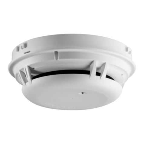
Siemens FDA241 User manual

Building Technologies
CPS Fire Safety
FDA241, FDA221 SintesoTM
Cerberus™ PRO
Siemens ASD
lPatented Technology
lCompatible with the Siemens FDnet/C-NET loops (requires FDCC221S option)
lAdvanced dual Wavelength optical detection (Blue & Infra-red)
lConfigurable as a Standalone via a USB port or via the Panel when on a
network loop using the optional FDCC221S
lOut-of-the-box installation and commissioning
lEarly detection of a wide range of airborne particle sizes
lAsyst software tool for sample pipe designs support
lProgrammable alarm thresholds
lThe unique chamber design ensures clean detection chamber optics
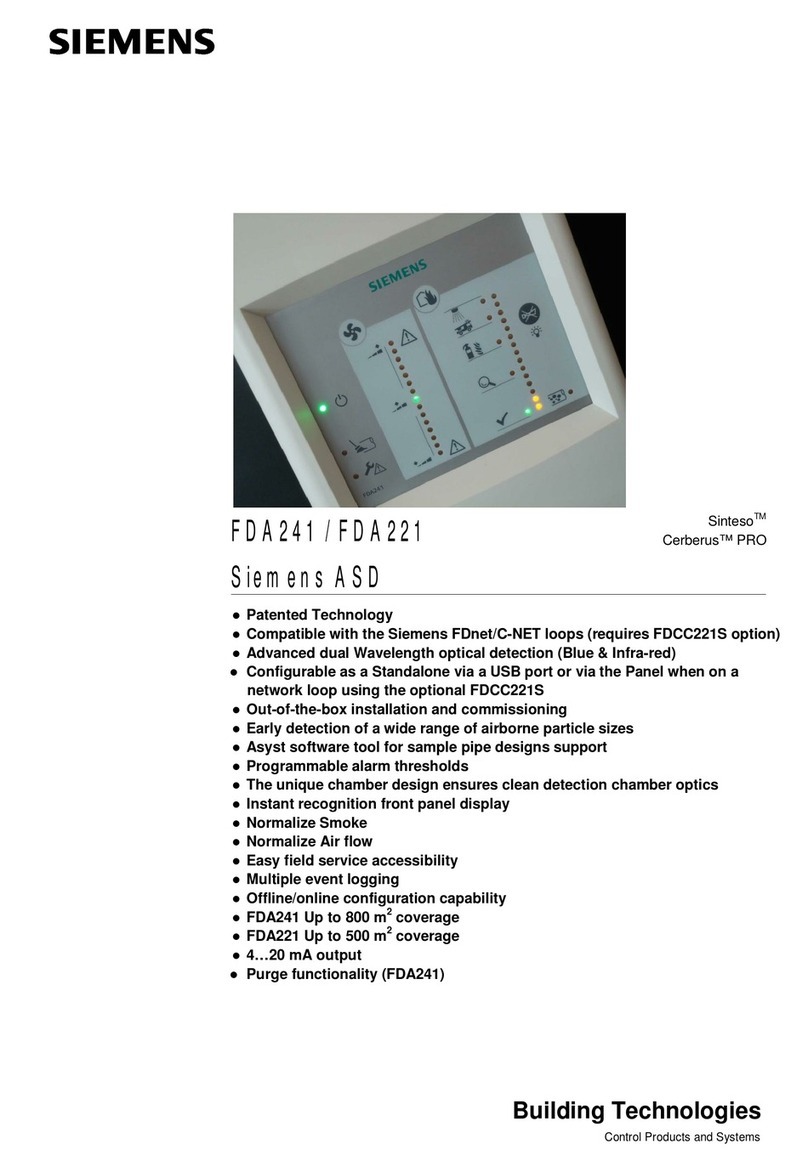
lInstant recognition front panel display
lNormalize Smoke
lNormalize Air flow
lEasy field service accessibility
lMultiple event logging
lOffline/online configuration capability
lFDA241 Up to 800 m2coverage
lFDA221 Up to 500 m2coverage
l4…20 mA output
lPurge functionality (FDA241)

2
Building Technologies
CPS Fire Safety
Siemens ASD FDA Series
The FDA241/221 series of detectors are a very early warning dual wavelength
(blue & infra-red) smoke detectors designed to protect small to medium, business-
critical environments up to 800 m2with the FDA241 or 500 m2with the FDA221).
The detector works by continually drawing air into sampling holes in a pipe net-
work. The air is passed into a uniquely designed detection chamber where light
scattering technology detects the presence of very small amounts of smoke.
Lower installation and service support costs
The FDA241 and FDA221 detectors can communicate directly on the
FDnet/C-NET loops (with an optional FDCC221S PCB), so there is no need for
separate relay or network connections. This reduces the cost of installation and
service. The detector acquires its loop address automatically.
Fire control panel programming (requires FDCC221S option)
The sophisticated integration on FDnet/C-NET allows for detector configurations,
maintenance and alarm/fault management to be performed centrally – at the fire
control panel. This increases control and lowers total solution cost.
Out-of-the-box operation
The FDA241 and FDA221 can be installed and commissioned out-of-the-box.
Normalize smoke density and air flow functionality, suitable default alarm and fault
thresholds makes for an easy installation.
Display
The front panel display includes an easy to read smoke
density and airflow level bar graph, alarm, fault status and
dust indicator (FDA241 only).
When the field service access cover is open, the user has
access to the Reset, Normalize Smoke & Flow buttons and
a mini USB communication connector.

3
Building Technologies
CPS Fire Safety
Legend to Indicators
Opening the detector
There are 2 modes for accessing the detector service area.
Partial access
Remove the 2 screws on the top of the detector. Slide the front cover upward until it
reaches the self locking tabs.
Full access
Remove the 2 screws on the top of the detector. Slide the front cover upward until it
reaches the self locking tabs. Grasp the cover on the sides and gently apply pres-
sure to spread the cover sides outward. This will enable the cover to be totally re-
moved
Warning: Take notice of the front panel connecting cable if fully removing the
cover.
Service Access – Display LEDs and Buttons
Flow OK
If self check is OK the Flow OK LED starts flashing to indicate normal operation
Smoke OK
If self check is OK the Smoke OK LED starts flashing to indicate normal operation
Alarm
The Alarm LED flashes in the event of a smoke alarm
Normalize flow button
As each installation will require a different sampling pipe configuration, this function
is used to set the zero reference for the bargraph. This function is required to be
done during commissioning of the detector. The nominal flow value which is deter-
mined during the normalize flow period is then the zero set point value for the air-
flow monitoring during normal operation.
To use this function, use a thin tool such as a paper clip or a small jeweller’s
screwdriver, place the tool into the hole and push the normalize flow button.
During the Normalization period the detector is still actively monitoring for smoke
using the default values.

4
Building Technologies
CPS Fire Safety
Normalize smoke button
This function is used to determine the nominal clean air value for the detector. This
is required to be done during commissioning. The nominal value which is deter-
mined during the normalize period is then the set point value for the smoke monitor-
ing during normal operation.
To use this function, use a thin tool such as a paper clip or jeweller’s screwdriver,
place the tool into the hole and push the normalize smoke button.
This function could be manually stopped by pressing the Normalize button again.
During the Normalization period the detector is still actively monitoring for smoke
using the default values.
Note:
The detector indicates over FDnet/C-NET) that normalizing is active (no distinguish-
ing between smoke and air flow)
Reset:
Pressing the Reset button, resets all latched states of the detector. Latched states
can be fire alarms or airflow out-of-range events. If a fire alarm is reset the associ-
ated relay is also reset.
Note:
If the detector is connected to FDnet, the alarms and associated relays are set to
non-latching
USB Connector:
The mini USB connector is used connect to a laptop when required to re-configure
the detector using the ASD Configuration Tool F-FXS2051
LED Test Function:
Press and hold the “Buzzer silence button” for 5 seconds.
The detector will cycle through a full LED display to check the operation of all LEDS
If connecting the Siemens ASD directly to a Siemens FDnet, C-NET loop, the FDCC221S communication card must
be ordered as a separate item. (S24218-A201-A2)

5
Building Technologies
CPS Fire Safety
Technical data
FDA241 FDA221
Input power
Voltage DC 19-30V √ √
Current @ DC 24 V 150 mA nominal,
250 mA in Alarm √ √
Dimensions (W x H x D) 162 mm x 285 mm x 120 mm √ √
Weight approx. 1.5 kg ( 3.3 Ibs) √ √
Protection category IP30 √ √
Mounting upright, inverted √ √
Sound power level L
WA
[dBA]
1
At suction speed High 37 33
Medium 33 30
Low 30 26
Operating conditions
Detector ambient -20 to 60 °C √ √
Humidity 5 to 95% (no condensation) √ √
Dust Indicator √
Sampling network
Maximum pipe lengths Single pipe length
Branched pipe lengths 60 m
2x60 m 30 m
2x25 m
Sampling hole options In accordance to the Asyst tool used for sample pipe modeling
Air inlet/exhaust pipe Metric: 25 mm Outside diameter (OD), Imperial 1.05 inches (US pipe)
Area coverage depending on local codes
and standards Up to 800 m² Up to 500 m²
System compatibility compatible with all Siemens FC20/FC720 (FS20/FS720 system)
Alarm Relay outputs
selectable Latching/Non Latching
rated 2.0A @ DC 30 V (max). NO/NC Contacts Qty 4 Qty 3
Fault Relays Qty 1 Qty 1
Cable access Rear 10 cm x 2.5 cm or top entry
Cable termination Screw terminals 0.2…2.5 mm
2
(30–12 AWG)
Other Interfaces Power in/out, 4-20 mA
Alarm threshold parameter sets
Fire 1 10 sets
0.05…2.0 % obs/m 5 sets
0.20…2.0 % obs/m
Fire 2 10 sets
2.0…20 % obs/m 5 sets
6.0…20 % obs/m
Individual alarm delays 0…300 seconds: Standard value 0 seconds smoke density, 15 sec Flow fault
Front Display
l4 Alarm state indicators (FDA241)
l3 Alarm state indicators (FDA221)
lFault Indicators
lPurge (FDA241)
lDust (FDA241)
lSmoke and Airflow level Bargraphs
Service Area
lStatus OK LEDs
lUSB connector
lReset
lSmoke and Airflow Normalize buttons
1A-weighted sound power level in [dB] as per DIN EN ISO 3744-2009
Measured with a pipe piece at the air inlet and at the air outlet

Siemens Switzerland Ltd
Building Technologies Division
International Headquarters
Gubelstrasse 22
CH-6301 Zug
Tel. +41 41 724 24 24
www.siemens.com/buildingtechnologies
© Siemens Switzerland Ltd, 2014
Data and design subject to change without notice.
Supply subject to availability.
Document no. A6V10331032_f_en_-- Manual FD20/FD720
Edition 2015-05-11 Register 3
Event log Time and date stamped in separate, non-volatile, logs for: smoke level, flow
level, detector status and faults
Normalize smoke & air flow
l
Set acceptable smoke alarm and fault thresholds
lUser adjustable period for airflow and smoke
lDuring Normalize period, pre-set default values are maintained
Warranty period
2 Years
Approvals
–VdS FDA241
G213050 FDA221
G213050
Details for ordering
Type Part no Designation Weight
FDA241 S54333-F17-A1 Aspirating smoke detector (8H) 2.500 kg
FDA221 S54333-F15-A1 Aspirating smoke detector (5S) 2.500 kg
Accessories FDCC221S S24218-A201-A2 Communications interface 0.019 kg
FP120-Z1 S54400-S122-A1 Power supply kit A (70 W) 3,920 kg
FA2003-A1 A5Q00019353 Battery (12 V, 7 Ah, VdS) 2,450 kg
FA2004-A1 A5Q00019354 Battery (12 V, 12 Ah, VdS) 3,930 kg
FA2005-A1 A5Q00019677 Battery (12 V, 17 Ah, VdS) 5,640 kg
You will find additional information in the following documents:
- Technical manual for Aspirating Smoke Detectors FDA241, FDA221,
Document A6V10334410
- Technical manual for Power supply kit FP120-Z1,
Document A6V10393194
Other manuals for FDA241
3
This manual suits for next models
5
Other Siemens Gas Detector manuals

Siemens
Siemens INTELLIGAS LYA14 Series User manual

Siemens
Siemens CC62P User manual

Siemens
Siemens QRB1 Series User manual

Siemens
Siemens Water Technologies Series User manual

Siemens
Siemens Sinteso Cerberus PRO FDA241 User manual
Siemens
Siemens OOHC941 User manual

Siemens
Siemens 5TG5930-3 Series User manual