E2658 is a series of flame proof gas detectors-transmitters intended for operation in
safe zones and ATEX Zones 2 and 22.
E2658 series devices are based on PluraSens® multifunctional platform and provide all
its features.
E2658 series has two independent analog outputs UT1 and UT2, user-selectable to
4-20 mA or 0-10 V, proportional either to gas concentration or temperature. RS485
Modbus RTU digital communication interface allows easy instrument configuration and
integration into various automation systems.
An option with relay outputs is available. Two relays RE1 and RE2 with closing contacts
can be used to switch 24 V or 230 V powered alarm sirens, ventilation fans, shut-off
valves or other actuators.
The instruments utilise gas sensors of various types with excellent repeatability, stability
and long lifetime
Please read this manual carefully before operating
Safety requirements
Always adhere to the safety provisions applicable in the country of use.
Do not perform any maintenance operation with the power on.
Do not let water or foreign objects inside the device.
Make sure that installation and maintenance are performed in the explosion safe
atmosphere.
The device should be properly earthed
It is crucial to tighten properly all the thread connections (screws, cable glands)
Use ATEX certified armoured cables or cable conduits
Avoid strong vibration and mechanical shock
Avoid direct sunlight
Avoid sources of strong electromagnetic interference
Do not use the device in the carbon disulfide atmosphere, since it may damage the
sealing gasket
Although E2658 series devises are suitable for use in the presence of flammable
dust, special precautions should be taken when operating in a dusty environment.
Dust may block the porous filter of the sensor and compromise results of
measurement. The detector should be inspected regularly if used in a dusty
atmosphere.
Choosing location
There are no precise rules or standards to follow when installing the gas detectors. The
following points must be taken into account:
safety: see Safety requirements section,
application (air quality control or leakage detection),
properties of the space under investigation (room geometry, direction and velocity of
air flows etc),
detected gas (relative density to air, whether the gas is flammable, or toxiс, or oxygen
displacing),
safety: strong vibrations, mechanical shock, and the sources of strong
electromagnetic interference should be avoided,
the device should be accessible for maintenance and repair.
For early leakage detection install the sensor as close as possible to the potential
leakage sources (flanges, valves, pressure reducers, pumps, etc), taking into
consideration other points listed above. For general area monitoring without definite
leakage sources, the detectors should be distributed evenly in the room. For personal
safety control the detectors are installed in the breathing zone (at the height of the head
of people or animals). Recommended sensor position is vertical, pointing downwards.
See Installation guidelines section for more information.
Installation and connections
Never perform installation or maintenance in explosive atmosphere
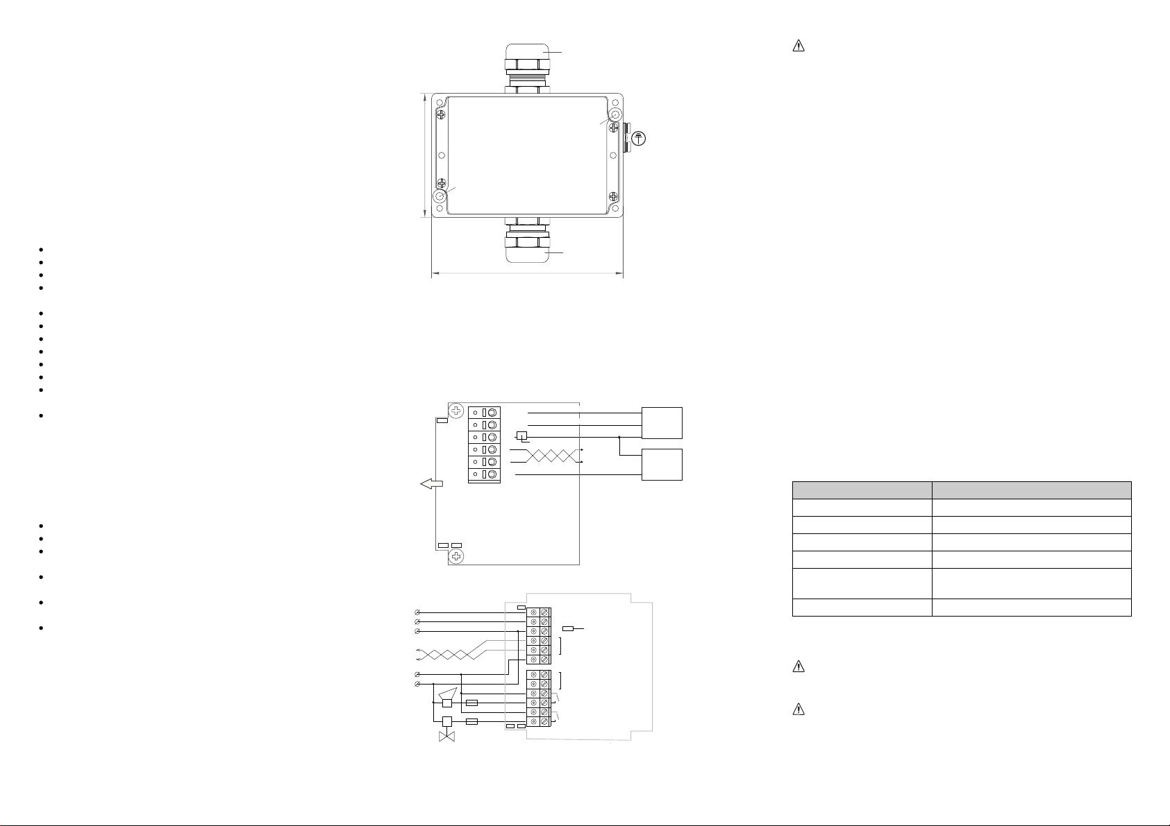
The device is fixed on the wall using two holes located outside the sealed area of the
device (see dimensional drawing below).
M25 (sensor)
M25 (cable entry)
125
fixing hole (Ø 5mm)
fixing hole (Ø 5mm)
1. Unscrew four lid screws and detach the lid from the detector.
2. Fix the detector on the wall and earth the enclosure using earthing terminal on the
side of the device. (This step may be done after the step 3, consider your convenience).
3. Use M25 cable glands to pass the cables of the power supply and of the external
devices. Plug the power cable and connect the analog/relay outputs and/or digital
interface terminals to the relevant devices according to the relevant connection
diagram.
Use ATEX certified armoured cables or cable conduits
The screwless quick connect spring terminals on the E2658 series devices are
suitable for a wide range of wires with cross-section 0,5...1,5 mm2. We recommend
to strip the wire end by 8...9 mm and tin it, or to use the wire end sleeves.
To connect the wire, insert the wire end into terminal hole. To disconnect, push the
spring loaded terminal lever, pull the wire out, and release the lever.
Use twisted pair cable, e.g. LiYY TP 2×2×0,5 mm2 or CAT 5, to connect the device
to RS485 network. Use one pair for A and B wires and the second pair for common
0 V and power +U wires to connect the transmitter to Fieldbus network. Respect
polarity. verall length of all connections via RS485 interface should not exceed
1200 m.
The type of each analog output can be independently changed between 4-20 mA
and 0-10 V with jumpers J1 ( UT1) and J2 ( UT2).
With closed jumper the output is 0-10 V, with open jumper the output is 4-20 mA.
By default both outputs UT1 and UT2 are assigned to gas concentration. The
device has built-in temperature sensor which may be tied to any of the outputs.
Note The outputs are not galvanically isolated from 24 V power supply and share
common 0V. Allowed load resistance limits are stated in Specifications table. To power
the instrument from an external 24 VDC source, connect terminals 0V and +U to the
source. If the integrated mains power supply module is used, connect terminals L and N
to the mains.
Note Actuator short-circuits should be avoided, to protect the instrument relays use
external fuses or safety switches.
The output assignments and scales can be changed by Modbus commands. (See
Annex 1 for more information.)
We recommend to set the difference between the upper and bottom limits of the
output scale not narrower than 20% of detection range (for C detectors the scales
down to 5% of range are allowed). In any case, do not set the output scale below
the tenfold resolution of the device.
4. Turn on the power. The sensor heating up may take up to five minutes after
switching on. A LED placed on the PCB of the device allows to control the
connection process. The LED response to different processes is presented in the
table below.
Process LED mode
Sensor heating period Blinking 0.5 Hz (50% on, 50% off)
Sensor absence or malfunction Blinking 0.5 Hz (90% off, 10% on)
Relay1 turned on Blinking 1 Hz (50% on, 50% off)
Relay2 turned on Blinking 2 Hz (50% on, 50% off)
Modbus response The signal is modulated with short on-off pulses,
even single Modbus cycle is traceable*
Normal measurement Continuous light
5. Make sure that the detector is properly fixed, the external devices connected,
power on and control LED is constantly lit. Place the lid back and fix it with the
screws.
Make certain that the cable gland and the screws fixing the front lid are
properly tightened to ensure the conformity to IP66 protection class. and
ATEX requirements
Make certain than the device is properly earthed.
The device is ready to use.
It is recommended to keep the device powered constantly, except for periods of
maintenance and calibration, deplacement etc.
4-20 mA / 0 -10
4-20 mA / 0 -10
0 / GN D
OUT1
OUT2
0
A
BRS485
+U = 11...30 D C
RE 1
RE2
Fieldb us
24 DC
S
N
L90...265 AC
J 3
Control LED
J1 J 2
J1: OUT1 type (open: 4-20 mA; closed: 0-10 )
J : OUT type2 2 (open: 4-20 mA; closed: 0-10 )
J : 3 return to fact ory settings
E2658 version with relays
OUT1
OUT2
0
A
B
+U
J3
J1 J2
Fieldbus
Controller
Supply
Power
Control LED
Input 1 4-20 mA / 0-10
Input 4-20 mA / 0-10 2
0 / GND
0
+24
SENSOR
E2658 basic version


