Helios 97948 User manual

1
Axialventilatoren Serie H . . .
Ventilateurs Helicoides serie H . . .
Axial-flow Fans serie H . . .
MONTAGE- UND BETRIEBSVORSCHRIFT
Nr. 97948
Zur eigenen Sicherheit sind alle nachstehenden Vor-
schriften genau durchzulesen und zu beachten!
EMPFANG UND EINLAGERUNG
Sendung sofort bei Anlieferung auf Schäden überprü-
fen; falls solche vorliegen umgehend Schadensmeldung
unter Hinzuziehung des Transportunternehmens veran-
lassen.
Bei Einlagerung über einen längeren Zeitraum sind zur
Verhinderung schädlicher Einwirkungen folgende Maß-
nahmen zu treffen: Versiegelung der blanken Teile mit
Korrosionsschutz, Schutz des Motors durch trockene
luft- und staubdichte Verpackung (Kunststoffbeutel mit
Trockenmittel und Feuchtigkeitsindikatoren). Der Lager-
ort muss erschütterungsfrei, wassergeschützt und frei
von Temperaturschwankungen sein.
Bei mehrjähriger Lagerung bzw. Motorstillstand muss
vor Inbetriebnahme eine Inspektion der Lager mit evtl.
Erneuerung der Fettfüllung und eine Isolationsprüfung
erfolgen. Bei Unterschreiten des Isolationswiderstandes
von 2 M Ohm bei 500 V Gleichspannung und 25 °C
Wicklungstemperatur ist der Motor bei maximal 80 °C
zu trocknen und danach die Prüfung zu wiederholen.
Bei Weiterversand (vor allem über längere Distanzen) ist
zu prüfen, ob die Verpackung für Transportart und -weg
geeignet ist.
Schäden, deren Ursprung in unsachgemäßem Trans-
port, Einlagerung oder Inbetriebnahme liegen, sind
nachweisbar und unterliegen nicht der Gewährleistung.
EINSATZBEREICH
Die Ventilatoren sind zur Förderung normaler oder leicht
staubhaltiger, wenig aggressiver und feuchter Luft, bei
normalen Temperaturen und im Bereich ihrer Leistungs-
kennlinie geeignet. Für den Einsatz in explosionsgefähr-
deten Bereichen ist eine spezielle Ausführung erforder-
lich.
Bei Betrieb unter erschwerten Bedingungen, wie z.B.
hohe Feuchtigkeit, längere Stillstandzeiten starke Ver-
schmutzung, übermäßige Beanspruchung durch klima-
tische, technische, elektronische Einflüsse ist Rückfrage
und Einsatzfreigabe erforderlich, da die Serienausführ-
ung hierfür u.U. nicht geeignet ist. Die Motoren besitzen
eine tropenfeste Isolation. Die Isolationsklasse und so-
mit mögliche thermische Belastung ist auf dem Typen-
schild, ebenso die Schutzart, angegeben. Es ist sicher-
zustellen, dass der normseitig vorgegebene Einsatz-
bereich nicht überschritten wird. Die serienmäßige Aus-
stattung erlaubt einen Einsatz im Temperaturbereich von
–35 °C bis +40 °C.
Ein bestimmungsfremder Einsatz ist nicht statthaft. Das
Gerät darf nicht im Freien und in Kontakt mit Wasser be-
trieben werden. Aufstellung im Freien ist mit entspre-
chender Sonderausrüstung möglich.
EINSATZ BEI RAUMLÜFTUNG
Zur Erreichung der erwarteten Ventilatorleistung ist eine
planmäßige Zuluftführung Voraussetzung. Bei Betrieb
von schornsteinabhängigen Feuerstellen im entlüfteten
Raum muss diesen, bei allen Betriebsbedingungen,
ausreichend Zuluft zugeführt werden.
LEISTUNGSDATEN
Das Motortypenschild gibt über die elektrischen Werte
Aufschluss; diese sind auf Übereinstimmung mit den
örtlichen Gegebenheiten zu überprüfen. Die Ventilato-
renleistungen wurden auf einem Prüfstand entspr. DIN
24163, Teil 2 ermittelt; sie gelten für Normbedingungen
(δ= 1,2 kg/m3), Nenndrehzahl und Normalausführung
bei Verwendung einer Einströmdüse, ohne Schutzgitter,
NOTICE D'INSTRUCTION POUR L'INSTALLATI-
ON, I'UTILISATION ET L'ENTRETIEN NO. 97948
Par mesure de sécurité, I'ensemble des prescripti-
ons qui suivent sont à lire attentivement et à res-
pecter!
RÉCEPTION ET STOCKAGE
Dès reception contrôler la livraison pour vérifier le bon
état du matériel. En cas d'avarie, faire dans les 24 heu-
res les réserves d'usage auprès du transporteur.
En cas de stockage prolongé, il appartient de prendre
les mesures suivantes pour eviter tout dommage: Proté-
ger les parties non traitées à l'aide d'un produit anticor-
rosif, envelopper les moteurs dans un emballage sec,
étanche à l'air et aux poussières (à l'aide, par ex. d'un
sac piastique dans lequel sera placé un agent déshy-
dratant avec Indicateur d'humidité).
Le matériel est à stocker dans un endroit abrité de l'eau,
exempt de variations de température et de vibrations.
Lors d'un stockage ou d'un non-fonctionnement du
moteur pendant plusieurs années, il faut procéder avant
la remisé en fonctionnement à un contrôle des roule-
ments (en remplaçant éventuellement leur réserve de
graisse) et de l'isolation électrique. Si celle-ci est in-
férieure à 2 M. Ohms sous une tension de 500 Volts et à
une température de bobinage de 25° C, le moteur doit
être séché à une température maximale de 80 °C. En-
suite le contrôle peut être réeffectué.
En cas de réexpedition du matériel (surtout pour de lon-
gues distances), il faut vérifier que le type d'emballage
est approprié au mode de transpor choisi.
Les dommages dus à de mauvaises conditions de
transport, à des stockages défectueux ou à une utilisa-
tion anormale sont sujets à vérification et contrôle et
entraînent la suppression de notre garantie.
DOMAINE D'UTILISATION
Ces ventilateurs sont destinés à l'extraction ou l'intro-
duction d'air dans des conditions normales de tempéra-
ture, d'humidité et de pression atmosphérique, avec
une basse teneur en poussières à faible agressivité et
dans la limite de leurs courbes de performance. Lors
d'utilisatign en milieu à risque d'explosion, une executi-
on speciale est nécessaire.
Pour des conditions d'utilisation difficiles telles que
forte humidité, longue période de non-fonctionne-
ment, fort encrassement, conditions d'utiiisation ri-
goureuses dues au climat au type d'application ou au
flux de régulation électronique, il est indispensable
d'obtenir l'accord du fabricant, car vraisemblablement
les matériels standard ne seront plus appropriés. Les
bobinagesmoteurs sont traités ' tropicalisation''. La
classe d'isolation (température max. utilisation) et le
type de protection (étanchéité, eau et/ou poussières)
sont indiqués sur la plaque signalétique du moteur. Il
faut s'assurer que l'application est bien en rapport
avec la norme définie sur la plague signalétique. L'é-
quipement standard permet une utilisation pour des
températures comprises entre –35 °C et + 40 °C.
Il n'est pas permis d'utiliser ces appareils pour d'autres
fonctions en dehors de leur utilisation normale. L'ap-
pareil ne doit pas être utilisé à l'air libre et ne doit jamais
être en contact avec de l'eau.
L'appareil ne peut être installé à l'air libre qu'en utilisant
l'équipement spécial correspondant.
UTILISATION POUR L'AÉRATION DE LO-
CAUX
Le débit indiqué pour chaque ventilateur ne peut être ef-
ficacement obtenu que si l'installation présente une ent-
rée d'air effective. En cas d'utilisation d'un ventilateur
dans une pièce équipée d'un chauffage à foyer ouvert, il
est nécessaire que les entrées d'air soient correctement
dimensionnées pour permettre l'approvisionnement suf-
fisant en air de renouvellement.
OPERATION AND INSTALLATION
INSTRUCTIONS INST. NO. 97948
To ensure your own security it is absolutely neces-
sary that the following instructions are thoroughly
read and observed.
RECEIPT AND STORAGE
Check consignment immediately upon receipt for da-
mages; in case of damage immediately arrange for sta-
tement of damage in consultation with the forwarding
agent.
When storing for a longer period of time the following
steps are to be taken to avoid damaging influences:
sealing of bare parts with anti-corrosion agent; protec-
tion of motor by dry air- and dustproof packing (plastic
bags witi drying agent and moisture indicators). The sto-
rage place must be water proof, vibration-free and free
of temperature variations.
When storing for several years or standstill of motor an
inspection of the bearings with possible re-lubrication
and an insulation inspection are absolutely necessary
before starting operation.
When falling below an insulation resistance of 2 M Ohm
at 500 V direct voltage and 25° C winding temperature
the motor has to be dried at a maximum temperature of
80 °C and the inspection then repeated.
When transshipping (especially over longer distances)
check if the packing is adequate for way and manner of
transportation.
Damages due to improper transportation, storage or
putting into operation are detectable and are not liable
for warranty.
OPERATION/USE
The fans are suitable for moving normal or slightly dusty,
almost non-agressive and slightly humid air at normal
temperatures and in the range of their performance cha-
racteristic curve. For use in explosive areas special exe-
cution is required.
For operation under difficult conditions i.e. high humidi-
ty, longer period of standstill, high pollution, excessive
working conditions through climatic, technical or elec-
tronic influences, further inquiry and operation release is
necessary as the standard execution might not be sui-
table.
The motors have tropical insulation. The insulation class,
the thermal load possible and also the protection class
are noted on the rating plate. It must be ensured that
the standardized range of application is not exceeded.
The standard execution is suitable for operation in am-
bient temperatures of –35 °C to + 40 °C.
The fan may only be used according to its intended pur-
pose. The fan may not be used outdoors and may not
come in contact with water during operation. Outdoor
use is possible in a corresponding special execution.
OPERATION AS ROOM VENTILATION DEVICE
In order to achieve the desired fan performance a syste-
matic air supply is imperative. When using chimney de-
pendant fire-places in ventilated rooms these must have
enough supply air no matter which operation conditi-
ons.
PERFORMANCE DATA
The motor rating plate provides information on the elec-
trical data; this data is to be examined for its conformity
to the local conditions.
The fan performances were determined on a test stand
according to DIN 24163, part 2; they are valid for the ra-
ted speed and standard execution by use of a coned in-
let, without protection grille at free suction and dischar-

2
Axialventilatoren Serie H . . .
Ventilateurs Helicoides serie H . . .
Axial-flow Fans serie H . . .
bei ungehinderter An- und Abströmung. Hiervon abwei-
chende Ausführungen und ungünstige Einbau- und Be-
triebsbedingungen können zu einer Reduzierung der
Förderleistung führen. Die Geräuschangaben beziehen
sich ebenfalls auf die vorstehend beschriebene Anord-
nung. Gehäusevariationen, ungünstige Betriebsbedin-
gungen u.a.m. können zu einer Erhöhung der angege-
benen Werte führen. Angaben, die sich auf bestimmte
Abstände (1, 2, 4 m) beziehen, gelten für Freifeldbedin-
gungen. Der Schalldruckpegel kann im Einbaufall erheb-
lich von der Katalogan- gabe abweichen, da er stark
von den Einbaugegebenheiten, d.h. vom Absorptions-
vermögen des Raumes, der Raumgröße u.a. Faktoren
abhängig ist.
BERÜHRUNGSSCHUTZ
Beim Einbau sind die gültigen Arbeitsschutz- und Un-
fallverhütungsvorschriften zu beachten.
Kontakt mit rotierenden Teilen muss verhindert werden.
Es ist sicherzustellen, dass sich im Ansaugbereich keine
Textilien (z.B. Vorhänge) oder andere ansaugbare Stoffe,
wie z.B. auch Kleidung von Personen, befinden.
Bestimmte Ventilatorentypen werden serienmäßig mit
saugseitigem Schutzgitter (DIN 31001) geliefert. In Ab-
hängigkeit der Einbauverhältnisse kann auch drucksei-
tig ein Berührungsschutz erforderlich sein. Entsprechen-
de Schutzgitter sind als Zubehör lieferbar. Ventilatoren,
die durch ihre Einbauweise, (z.B. Einbau in Lüftungs-
kanäle oder geschlossene Aggregate geschützt sind,
benötigen kein Schutzgitter, wenn die Anlage die glei-
che Sicherheit bietet (siehe DIN 31001 und 24167). Es
wird darauf hingewiesen, dass der Installateur für Unfäl-
le infolge fehlender Schutzeinrichtungen haftbar ge-
macht werden kann.
FÖRDER- UND DREHRICHTUNG
Die Förderrichtung – sofern nicht anders bestellt - ist bei
den Typen HQ, HW, HS, AVDDK über den Motor sau-
gend = Ausführung „A“ und bei den Typen HRF, AVDRK
drückend = Ausführung „B“. Die hierzu richtige Dreh-
richtung – bei Blick über den Motor – ist links (gegen
Uhrzeigersinn). Die Luftförderrichtung kann durch Än-
dern der Drehrichtung (siehe Schaltbild) geändert wer-
den. Die Ventilatorleistung verringert sich dabei um ca.
1
/
3
. Die Geräuschangaben werden bei Betrieb in anor-
maler Drehrichtung erheblich überschritten.
DREHZAHLREGELUNG
Sofern im Katalog vermerkt, sind die Ventilatoren mit-
tels Spannungsreduzierung oder Frequenzumrich-
tung drehzahlsteuerbar. Hierfür nicht freigegebene
Typen dürfen nicht drehzahlgesteuert werden. Für
ausreichende Motorkühlung und Sicherstellung der
Funktion muss eine Mindestdrehzahl/Spannung die
auch von bauseitigen Widerständen, Winddruck
u.a.m. abhängig ist, eingehalten werden.
Bei der Bemessung der Steuergeräte ist zu beach-
ten, dass innerhalb des geregelten Spannungsfeldes
Stromspitzen auftreten können. Die Steuergeräte
sind deshalb entsprechend unseren technischen An-
gaben zu dimensionieren. Passende Steuergeräte
werden als Zubehör angeboten.
ACHTUNG: Der Einsatz von Fremdfabrikaten kann
vor allem bei elektronischen Geräten, zu Funktions-
problemen, Zerstörung des Reglers und/oder des
Ventilators führen. Bei Einsatz seitens Helios nicht
freigegebener Regelgeräte, entfallen Garantie- und
Haftungsansprüche.
MONTAGE
Die Ventilatoren werden serienmäßig als komplette Ein-
heit, d.h. anschlussfertig geliefert. Sie können in beliebi-
ger Achslage eingebaut werden.
ACHTUNG: Nachfolgende Ausführungen "Kondens-
wasserbildung" sind zu beachten.
Um ein Verziehen des Ventilatorgehäuses und somit ein
Streifen des Laufrades zu verhindern, muss eine ebene
Anschraubfläche gegeben sein. Falls nötig diese durch
entsprechenden Ausgleich herstellen.
PERFORMANCES TECHNIQUES
Sur les plaques signalétiques des moteurs sont portées
les caractéristiques électriques. Il est nécessaire de véri-
fier la conformité avec les valeurs locales. Les perfor-
mances des ventilateurs ont été déterminées sur un
banc d'essai conformément à la norme DIN 24 163
2ème partie. Elles sont valables pour la vitesse nomina-
le, dans l'exécution standard, équipée d'un cône à l'a-
spiration, sans grille de protection. Lors du test, aspira-
tion et refoulement sont dégagés de toutes entraves
pour assurer une libre circulation de l'air. Des exécuti-
ons autres que l'exécution standard, des conditions
d'installation et d'utilisation défavorables peuvent con-
duire à une réduction des performances.
Les valeurs acoustiques sont également en conformité
avec les essais définis ci-dessus. Des exécutions dif-
férentes pour les caissons, des conditions d'utilisation
défavorables, etc. peuvent conduire à une hausse des
valeurs indiquées. Les valeurs données quelles que
soient les distances (1, 2, 4 m) sont mesurees en champ
libre. Suivant les conditions d'utilisation, les niveaux
acoustiques résultants peuvent être très différents des
données du catalogue (bruits amortis, bruits régénérés,
incidence de la directivité, de la distance etc . . .).
PROTECTION CONTRE TOUT CONTACT
ACCIDENTEL
Lors de l'installation, il faut respecter strictement les pre-
scriptions concernant la protection du travail et la
prévention des accidents. Tout contact avec les pièces
en rotation doit être évité. Il faut veiller à ce que des tex-
tiles (par ex. rideaux) ou autres tissus pouvant être
aspirés, voire par ex. également vêtements, ne se trou-
vent pas dans le champ d'aspiration de l'appareil.
Certains types de ventilateurs sont équipés en série d'u-
ne grille de protection côté aspiration (DIN 31 001). Se-
lon les conditions d'installation, un système de protec-
tion peut être également nécessaire côté refoulement.
De telles grilles de protection font partie du programme
"accessoires". Pour les ventilateurs qui sont protégés
par leur type d'installation (par ex. intégration dans des
gaines d'aération ou dans des enceintes fermées), une
grille de protection n'est pas nécessaire dans la mesure
où l'installation apporte la même sécurité (voir norme
DIN 31 001 et 24 167).il est rappelé que la responsabi-
lité de l'installateur sera engagée pour tout accident dû
à l'absence de systèmes de protection.
SENS D'ÉCOULEMENT DE L'AIR ET SENS
DE ROTATION
Le sens d'écoulement de l'air se fait (sauf indications
contraires) du moteur vers l'hélice et se dénomme "Exé-
cution A". Dans cette exécution, le sens de rotation du
moteur se fait dans le sens inverse des aiguilles d'une
montre (moteur vu de face). Le sens d'écoulement de
l'air peut être inversé en changeant le sens de rotation
du moteur (voir schéma de connexion), mais le débit de
l'air se trouve diminué d'environ
1
/
3
de sa valeur nomina-
le et le niveau de bruit augmente sensiblement.
RÉGULATION DE VITESSE
Les ventilateurs sont régulables par réduction de tensi-
on ou par variation de la fréquence, dans la mesure où
le ventilateur choisi est régulable; cette indication figure
dans nos catalogues. On ne doit pas tenter de réguler
un ventilateur non adapté à cette fonction.
Pour assurer un refroidissement suffisant du moteur et
la sécurité de fonctionnement, on doit maintenir une vi-
tesse/tension minimum qui dépend entre autres de la
perte de charge des éléments du local, de la pression
du vent etc.
Pour déterminer un régulateur, il faut tenir compte de l'in-
tensité maximale que peut absorber le moteur en cours
de régulation. Pour cette valeur se reporter à nos
données techniques électriques. Des régulateurs appro-
priés sont fournis sur demande et figurent dans nos
matériels annexes.
ge. Diverging execution and adverse installation- and
operation conditions can lead to a reduction of perfo rm
an ce .
The noise data also refers to the above mentioned con-
figuration. Variations in housing, adverse operating con-
ditions etc. can lead to an increase of the given data.
Data which applies to certain distances (1, 2 and 4 m) is
valid for free field conditions.
At installation the sound pressure level can differ consi-
derably from the catalogue given data, as it depends ex-
tremely on the installation conditions, i .e. on the sound-
absorption capacity of the room, its size and other
factors.
PROTECTION AGAINST ACCIDENTAL
CONTACT
When installing observe the valid regulations for labour
protection and accident prevention.
Any contact with rotating parts must be avoided. Make
sure that no textiles (such as curtains) or other materials
which could be sucked in, as for instance clothing are
close to the suction area of the fan.
Certain fans are delivered serially with a protection grille
on the suction side (DIN 31001). Depending on the in-
stallation conditions a contact safety device on the di-
scharge side may be necessary. Corresponding grilles
are available as accessories.
Fans protected by their installation in ventilation chan-
nels or closed aggregates do not need a protection gril-
le, if the installation guarantees the same protection (see
DIN 31001 and 24167). We emphasize that the installer
will be held responsible for accidents occuring as a re-
sult of missing protection devices.
AIR-FLOW DIRECTION AND DIRECTION OF
ROTATION
The air-flow direction - as long as not ordered otherwise
- is suction across the motor = execution ,,A". The cor-
rect direction of rotation – when looking over the motor
– is to the left (counter-clockwise). The air-flow direction
can be changed by changing the direction of rotation
(see wiring diagram). In this case the performance of the
fan is reduced by approximately
1
/
3
. The sound data in-
creases considerably at anomalous direction of ratation.
SPEED CONTROL
As far as stated in the catalogue the fans are speed
controllable, either by voltage reduction or frequency in-
verters. Types not released for regulation may not be
speed controlled.
In order to ensure sufficient cooling of the motor and
maintenance of functioning a minimum speed/voltage
also depending on the pressure losses in the building,
of the ventilation system, wind pressure etc. must be
kept.
When deciding on a controller please note that current
maximum peaks may occur within the controlled elec-
tric field. The controllers must be dimensioned accor-
ding to our technical data. Suitable controllers are avai-
lable as accessories
ATTENTION: The use of other brands, especially
other electronic devices, can lead to malfunctioning
and even distruction of the controiler and/or the fan.
Controllers which haven't been cleared by Helios
are not liable for warranty and guarantee claims.
MOUNTING
The fans are delivered in standard execution as a com-
plete unit, i.e. ready for installation. Installation is possi-
ble in every axle position.
ATTENTION: Following instructions "condenserwa-
ter development" are to be observed.
In order to avoid distortion of the fan-housing and also a
brushing of the impeller an even mounting surface must
be given. If necessary this must be achieved by balan-
cing.

3
Axialventilatoren Serie H . . .
Ventilateurs Helicoides serie H . . .
Axial-flow Fans serie H . . .
EINBAU
Beim Einbau ist auf Unterbindung von Körperschallü-
bertragung zu achten. Hierzu, z.B. beim Zwischenset-
zen in Rohrleitungen flexible Verbindungsstücke (Segel-
tuchstutzen) verwenden (siehe Zubehör). Beim Einbau
in Beton- und Leichtbauwände, Holzpaneelen, zu star-
kes Anziehen der Befestigungsschrauben vermeiden.
Gegen Lockerung geeignete Schraubensicherung ein-
setzen. Bei Rohreinbau ist darauf zu achten, dass vor
und hinter dem Ventilator eine ausreichend lange gera-
de Rohrstrecke vorgesehen wird, da sonst mit erhebli-
chen Leistungsminderungen und mit Geräuscherhöhun-
gen zu rechnen ist. Bei Wandeinbau und späterem
Verputzen kann das Gehäuse mit einer Folie umwickelt
werden, so dass es bei Bedarf wieder leicht heraus-
nehmbar ist.
ACHTUNG: Die volle Ventilatorleistung wird nur er-
reicht, wenn freie An- und Abströmung gegeben ist.
Für ausreichende Motorkühlung muss sichergestellt
sein, dass eine Mindest-Luftströmungsfläche von
20% des Ventilatorquerschnittes gegeben ist.
KONDENSWASSERBILDUNG
Bei periodischem Betrieb, bei feuchten und warmen
Fördermitteln und durch Temperaturschwankungen
(Aussetzbetrieb) entsteht innerhalb des Motors Konden-
sat, dessen Abfluss sichergestellt werden muss.
Motorgehäuse und Klemmenkastendeckel (rückseitig
am Motor) sind hierzu serienmäßig (ausgenommen EEx
e-Ausführung) mit je einer Kondensatöffnung versehen.
Die Öffnung im Klemmenkastendeckel ist mit einem gel-
ben Kunststoff-Stopfen verschlossen. Die Öffnung vor-
ne am Umfang des Motorgehäuses ist offen.
Bei horizontaler Achslage ist der Ventilator so zu drehen,
bzw. einzubauen, dass die Kondenswasseröffnung un-
ten liegt.
Bei vertikaler Achslage mit Laufrad nach oben, ist der
Stopfen im Klemmenkastendeckel zu entfernen und
dann die Öffnung vorne im Motorgehäuse zu versch-
ließen. Die Kondenswasseröffnung muss immer an der
tiefsten Stelle liegen. Bei Schäden durch falsche Anord-
nung entfallen jegliche Garantieansprüche.
FUNKTIONSSICHERHEIT – NOTBETRIEB
Bei Einsatz des Ventilators in wichtiger versorgungs-
technischer Funktion, ist die Anlage so zu konzipieren,
dass bei Ventilator-Ausfall automatisch ein Notbetrieb
garantiert ist. Geeignete Lösungen sind z.B.: Parallelbe-
trieb von zwei leistungsschwächeren Geräten mit ge-
trenntem Stromkreis. Standby-Ventilator, Alarmeinrich-
tungen und Notlüftungssysteme.
ELEKTRISCHER ANSCHLUSS
ACHTUNG: Der elektrische Anschluss darf nur von
einer Elektrofachkraft ausgeführt werden.
Alle Arbeiten in spannungslosem Zustand vorneh-
men. Die einschlägigen Sicherheits- und Installati-
onsvorschriften sind zu beachten.
Zwingend vorgeschrieben sind:
– ein allpoliger Netztrennschalter mit mindestens 3 mm
Kontaktöffnung und
– ein geeignetes Schutzgerät für jeden Ventilator bzw.
jede Drehzahl (bei mehrtourigen Ventilatoren).
Netzspannung und Frequenz müssen mit den Angaben
des Motorleistungsschildes übereinstimmen.
Bei Anschluss an Kunststoff-Klemmenkästen dürfen
keine Kabelverschraubungen aus Metall verwendet wer-
den. Die Einführung der Zuleitung so vornehmen, dass
bei Wasserbeaufschlagung kein Eindringen entlang der
Leitung ermöglicht wird. Leitung nie über scharfe Kan-
ten führen. Anschluss und Anordnung der Schaltbü-
gel/Brücken nach beiliegendem Schaltbild vornehmen.
Schutzleiter an Erdungsklemme anschließen.
Für Servicearbeiten einen allpolig abschaltenden Repa-
raturschalter in unmittelbarer Nähe des Ventilators vor-
sehen. Weitere Arbeitsgänge siehe unter Abschnitt "In-
betriebnahme".
ATTENTION: Toute utilisation d'un régulateur non
agréé peut conduire, tout particulièrement dans le
cas des régulateurs de vitesse électroniques, à des
problèmes de fonctionnement, à sa destruction ou
à celle du moteur. Dans ce cas, toute demande de
garantie et engagement de responsabilité seront re-
jetes par Helios.
MONTAGE
Les ventilateurs standard sont livrés complets assem-
blés prêts à raccorder. Ils peuvent être installés en posi-
tion verticale, horizontale ou inclinée.
ATTENTION: Les explications qui suivent concer-
nant les "trous d 'écoulement des condensats" sont
à respecter. Toutefois, on veillera notamment pour
les ventilateurs muraux à ce que la platine support
applique parfaitement sur la surface et ne soit pas
déformée par le serrage aux points de fixation.
INSTALLATION
Lors de l'installation il faut veiller à limiter la transmission
de bruits par vibration. Il est donc conseillé de prévoir
pour le raccordement en gaines des manchettes sou-
ples disponibles dans nos accessoires. Lors d'une in-
stallation dans des murs en béton et de construction
légère ou dans des panneaux de bois, éviter que les vis
de fixation soient trop serrées. Pour éviter un desserra-
ge, utiliser une consolidation de vis appropriée.
Pour une installation en gaine, il est également néces-
saire de laisser en amont et en aval de l'appareil une
longueur de gaine droite suffisante. Cette disposition
évite des chutes de rendement et l'augmentation de l'in-
tensité sonore. Pour un montage encastré dans un mur
qui sera crépi plus tard, le boîtier peut être enveloppé
dans une feuille de protection; il pourra être ainsi retiré
sans probleme, si necessaire.
ATTENTION: Le débit maximum d'un ventilateur n'est
effectif que si l'entrée ou la sortie d 'air a été normale-
ment dimensionnée dans l'installation. Pour un refro-
idissement suffisant du moteur, il est nécessaire d'as-
surer des surfaces de passage d'air au moins égales
à 20 % de la section du ventilateur.
FORMATION DE CONDENSATS
En cas de fonctionnement intermittent, de transport de
fluides humides ou chauds de variations de températu-
re, il se forme à l'intérieur du moteur un condensat (con-
densation d'eau) qui doit absolument être évacué. Le
carter du moteur et le cache du boîtier de raccordement
(situé à l'arrière du moteur) sont équipés dans leur versi-
on standard d'un trou d'évacuation des condensats.
(Nota: cette disposition n'existe pas pour les moteurs
classés EEx e atmosphères explosibles). Le trou du
boîtier de raccordement est fermé par un opercule jau-
ne. Le trou situé sur la flasque avant du moteur est ibre.
En fonctionnement axe horizontal, le ventilateur doit être in-
stallé de telle sorte que le trou d'écoulement soit mis vers
le bas.
En fonctionnement axe vertical avec hélice vers le haut,
il faut retirer l'opercule de la boîte à bornes et fermer en-
suite le trou situé sur le carter du moteur. Il convient de
noter que l'eau de condensat doit toujours s'écouler par
le point le plus bas.
Le non-respect de la règle d'évacuation des conden-
sats entraîne la perte de garantie.
SÉCURITÉ DE FONCTIONNEMENT –
SYSTÈME DE SECOURS
Lorsque le ventilateur a une fonction technique détermi-
nante, l'installation doit être conçue de sorte qu'un sy-
stème de secours soit automatiquement assuré en cas
de défaillance du ventilateur. Les solutions suivantes
peuvent être envisagées: fonctionnement simultané de
deux appareils de performances inférieures sur deux
enceintes séparées, ventilateur en stand-by, dispositifs
d'alarme, systèmes d'aération de secours.
INSTALLATION
When installing heed to obviate body sound transmissi-
on, e.g. by using flexible connectors when installing in
ducts (see accessories). When installing in concrete and
light weight constructed walls and wood panels avoid
tightening the fixing screws too tightly. To prevent loose-
ning secure screws accordingly. When installing in ducts
make sure that there is a sufficiently long, straight piece
of duct in front and behind the fan as otherwise consi-
derable performance reduction and noise increase will
result. When installing in walls and later roughcasting the
housing can be wrapped in plastic foil so that it is easily
removable.
ATTENTION: The max. fan performance can only be
achieved if unhindered suction and discharge is
provided. For a sufficient cooling of the motor a mi-
nimum air-flow area of 20% of the fan cross section
must be guaranteed.
CONDENSER-WATER DEVELOPMENT
In case of periodical use, moist and warm media and
through temperature variations (intermittent service)
condensate is built up in the motor and its draining off
must be ensured.
Motor housing and terminal box lid (on the backside of
the motor), are serially supplied with one condensate
opening each (except in EEx e executions). The opening
in the terminal box lid is closed by a yellow plastic plug.
The opening at the front of the motor housing is open.
When installed at a horizontal axle position the fan must
be turned until the condenser-water opening shows do-
wnwards. When installed at a vertical axle position with
the impeller pointing upwards the plug in the terminal
box must be removed and then the motor housing must
be closed The condenser-water opening must always
be the lowest point.
In case of damage through incorrect installation HELIOS
is released from all guarantee claims.
SECURITY OF OPERATION - EMERGENCY
OPERATION
When using the fan in important functions it must be in-
stalled so that in case of a fan breakdown an emergen-
cy operation is guaranteed. Suitable solutions are: par-
allel operation of 2 devices of lower performance with
separated current supply, standby fan, alarm and emer-
gency ventilation systems.
ELECTRICAL CONNECTION
ATTENTION: Electrical connection may only be car-
ried out by specially trained personnel.
All work only in dead state. All relevant security and
installation regulations are to be observed.
Peremptory regulations are:
– an all-pole mains switch with a minimum contact ope-
ning of 3 mm and
– a suitable protection device for each fan resp. each
speed (for fans with more than one speed).
Power-supply voltage and frequency must correspond
to the data on the motor rating plate.
When connecting to plastic terminal boxes no metal
screw-type conduit fittings may be used. The introduc-
tion of the power cable must be done such that in case
of water an entry along the power-supply cable is im-
possible. The connecting cable may not touch sharp
objects. Connection and arrangement of the switch
bridges according to enclosed wiring diagram. Connect
protective conductor to grounding terminal.
For further working processes see "Putting into operati-
on".
For maintenance an all-pole disconnecting isolator
should be installed directly by the fan.

4
Axialventilatoren Serie H . . .
Ventilateurs Helicoides serie H . . .
Axial-flow Fans serie H . . .
MOTORSCHUTZ
a) Motoren ohne eingebaute Temperaturwächter (Ther-
mokontakte oder Kaltleiter): Absicherung durch Mo-
torschutzschalter. Alle drei Strombahnen zur gleich-
mäßigen Erwärmung des Bimetalls anschließen. Bei
mehrtourigen Motoren ist jede Drehzahl separat ab-
zusichern. Motorschutzschalter ca. 10-15% über
dem auf dem Ventilatorleistungsschild angegebenen
Strom einstellen. Auslösefunktion des Schalters durch
Einschalten testen. Schutzschalter sollte innerhalb 60
Sekunden auslösen.
ACHTUNG: Diese Absicherung ist nicht für dreh-
zahlgesteuerten Betrieb geeignet und schützt den
Motor nicht bei zu hoher Fördermitteltemperatur
oder mangelnder Kühlung.
b) Ventilatoren mit eingebauten Thermokontakten: Die-
se tragen auf dem Motordatenschild die ergänzende
Typenbezeichnung . . . TK. Zum Anschluss werden
die speziell entwickelten Motorvollschutzgeräte
MW = für 230 V ~
MD = für 400 V/3~, 1-tourig
M 2 = für 2-tourige getrennte Wicklung 400 V/3~
M 3 = für 2-tourige Dahlander-Wicklung 400 V
M 4 = für 2-tourige Y/∆-Schaltung 400 V/3~
empfohlen.
c) Ventilatoren mit eingebauten Kaltleitern: Diese sind
mit einem PTC-Aufkleber versehen bzw. durch einen
Hinweis im Klemmenkasten gekennzeichnet.
ACHTUNG: Die max. Prüfspannung für Kaltleiter
(PTC) von 2,5 V darf nicht überschritten werden,
da sonst Kaltleiter und Motorwicklung zerstört
werden!
Zur Motorüberwachung nur speziell für Kaltleiter ge-
eigneten Motorvollschutz-Schalter MSA. (Zubehör,
Best.-Nr. 1289) verwenden.
GERÄT HERGESTELLT NACH RICHTLINIE
94/9/EG
Für Einsatz, Anschluss und Betrieb gelten besondere
Bestimmungen (z.B. EN 50014); bei Zweifel ist Rückfra-
ge erforderlich. Helios explosionsgeschützte Ventilato-
ren entsprechen den Anforderungen der ATEX (Richtlinie
94/9/EG – Gerätesicherheitsgesetz). Zur Bewertung der
explosionsgefährdeter Bereiche ist eine Einteilung durch
den Betreiber in Zonen erforderlich. Es dürfen nur Venti-
latoren mit entsprechender, für die jeweilige Zone zuge-
lassener Gerätekategorie, verwendet werden. Weitere
Informationen sind der Helios-Druckschrift-Nr. 94318,
sowie den einschlägigen Normen und Gesetzestexten zu
entnehmen. Drehzahlregelung und anormal häufiges
Ein-/Ausschalten ist nicht zulässig.
Die auf dem Motorleistungsschild angegebene Tempe-
raturklasse des Motors muss mit der Temperaturklasse
des möglicherweise auftretenden Luft-Gasgemisches
übereinstimmen. Jedem Motor (bei polumschaltbaren
jeder Drehzahl) muss ein Motorschutzschalter vorge-
schaltet sein, der auf den Motorennennstrom einzustel-
len ist und bei festgebremstem Laufrad innerhalb der
aus dem Motorleistungsschild angegebenen Zeit tE
auslöst. Die Funktion ist anhand der dem Schutzschal-
ter beiliegenden Auslöskennlinie zu überprüfen.
Auf die Beachtung der diesen Geräten noch speziell bei-
liegenden Vorschriften wird hingewiesen.
Das Ansaugen
oder Eintreten von Fremdkörpern in den Ventilator muss
mittels Schutzvorrichtungen entspr. IP 20 bzw. mit Gitter-
abstand von max. 12 mm verhindert werden.
Der ungehemmte Lauf des Laufrades und die Leichtgän-
gigkeit der Lager sind mindestens einmal jährlich zu über-
prüfen.
Reparaturen müssen von Helios-Werkstätten
durchgeführt oder von einem amtlich anerkannten
Sachverständigen abgenommen werden.
INBETRIEBNAHME
gemäß VDE 0100/Teil 600
Folgende Kontrollarbeiten
sind auszuführen:
– Bestimmungsgemäßen Einsatz des Ventilators über-
prüfen
– Netzspannung mit Leistungsschildangabe verglei-
chen
BRANCHEMENT ÉLECTRIQUE
ATTENTION: Le branchement électrique doit être ef-
fectué par un électricien qualifié.
Tous les travaux doivent être effectués hors tension.
Les consignes de sécurité et les règles d'installati-
on en vigueur doivent être respectées.
Les prescriptions suivantes sont absolument de rigueur:
– disjoncteur omnipolaire avec ouverture de contact
d'au moins 3 mm
– dispositif de protection approprié pour chaque venti-
lateur voire pour chaque vitesse (dans le cas de mo-
teurs à plusieurs vitesses).
La tension secteur et la fréquence doivent correspondre
aux indications de la plaque signalétique du moteur.
Pour des branchements sur des boîtes à bornes en ma-
tière synthétique, il est interdit d'utiliser des pressesé-
toupes metalliques. Le passage du câble d'alimentation
doit être effectué de telle sorte qu'un éventuel filet d'eau
ne puisse pas s'infiltrer le long du cable. Ne jamais faire
passer le câble par-dessus d'objets coupants. Le bran-
chement et la mise en place de shunt doivent être réa-
lisés conformément au schéma de branchement joint.
Raccorder l'appareil à la terre par le câble et la borne
correspondante. Pour des travaux de maintenance, un
interrupteur coupant tous les pôles doit être installé à
proximité immédiate du ventilateur.
Pour les autres opérations, se reporter à la rubrique "Mi-
se en marche".
PROTECTION DU MOTEUR
a) Moteurs sans protection thermique incorporée (sans
thermocontacts ou thermistances). Assurer la sécu-
rité par un discontacteur. Ii est impératif de raccorder
les trois conducteurs pour être sûr d'un échauffement
homogène des bilames. Pour les moteurs à plusieurs
vitesses, chaque vitesse doit être protegée séparé-
ment. Le contacteur de protection doit être réglé sur
un courant d'environ 10 à 15 % supérieur à celui indi-
qué sur la plaque signalétique du ventilateur. Con-
trôler la fonction de déclenchement du thermique en
mettant en route le ventilateur dont on bloquera vo-
lontairement l'hélice. Le discontacteur doit alors se
déclencher en moins de 60 secondes.
ATTENTION: Cette protection n'est pas adaptée
pour un fonctionnement en régulation et ne prote-
ge pas le moteur contre des températures du flui-
de véhiculé trop élevées ou contre un refroidisse-
ment insuffisant.
b) Ventilateurs avec thermocontacts incorporés
La plaque signalétique du moteur indique en plus de
la désignation du type . . . TK. Pour leur branchement,
on conseille d'utiliser les appareils de protection tota-
le du moteur suivants:
MW= pour 230 V~
MD = pour 400 V/3~, 1 vitesse
M 2= pour bobinage séparé à 2 vitesses 400 V/3 ~
M 3= pour bobinage Dahlander à 2 vitesses 400 V/3 ~
M 4= pour accouplement Y/ƈ 2 vitesses 400 V/3 ~.
c) Ventilateurs équipés de sonde à thermistances : ils
sont équipés d'autocollants de signalisation (CTP) et
marqués dans la boîte à bornes.
ATTENTION: la tension maximum pour les sondes
à thermistances CTP ne doit pas dépasser 2,5 V
au risque d'endommager les thermistances et
l'enroulement!
Pour la protection moteur, utiliser uniquement un au-
xiliaire de commande MSA (accessoires, N° Réf.
1289).
APPAREIL FABRIQUÉ SELON LA DIRECTIVE
94/9/CE
L'installation, le branchement ainsi que le fonctionne-
ment de ces ventilateurs sont soumis à des dispositions
particulières (par ex. EN 50014); en cas de doute il est
indispensable de contacter le fabricant. Helios sont
conformes aux préconisations de la norme ATEX (Direc-
tive 94/9/EG – loi sur la protection des appareils). Pour
définir les protections nécessaires, un classement des
MOTOR PROTECTION
a) For motors without built-in automatic temperature
controller (thermal contact or PTC-resistor): Protec-
tion by motor-protection switch. Connect all 3 cur-
rent paths to ensure proportionate heating of the bi-
metal. For motors with more than 1 speed each
speed must be protected separately. Adjust motor-
protection switch approximately 10-15% higher than
the current noted on the fan rating plate. Test release
function of the switch by turning on the fan and
blocking the impeller. The motor-protection switch
should break the circuit within 60 seconds.
ATTENTION: This protection is not suitable for
speed controlled operation and does not protect
the motor at high air-flow temperature or lacking
cooling.
Fans with built-in thermal contacts: These have
theadditionaltypedesignationTK. For connecting we
recommend these especially developed motor-pro-
tection devices:
MW – for 230 V~
MD – for 400 V/3~, one speed
M 2 – for 2 speed separated winding 400 V/3~
M 3 – for 2 speed Dahlander winding 400 V/3~
M 4 – for 2 speed Y/D connection circuit 400/3
~ phase
c) Fans with built-in PTC-resistors: marked with PTC-
label or information in terminal box.
ATTENTION: Test voltages higher than 2,5 V can
damage the PTC and in addition destroy the elec-
tric coil.
For thermal overload protection of the motor use the
full motor protection unit MSA (accessory, Ref.-No.
1289).
MANUFACTURED EQUIPMENT COMPLYING
WITH DIRECTIVE 94/9/EC
Use connection and operation underlie special regulati-
ons (e.g. EN 50014); in cases of doubt further inquiry is
necessary. Helios explosion proof fans are in accordan-
ce with the specification ATEX (directive 94/9/EC -
equipment safety law). For the evaluation of the explosi-
ve area an allocation into zones is necessary by the ope-
rator. Only fans with adequate, for the respective zone
certified product category may be used. For further in-
formation see Helios leaflet no.94318, as well as the re-
levant standards and wordings of law.
Speed control and continuous turning on and off is not
permitted.
The temperature class of the motor noted on the motor
rating plate has to correspond to the temperature class
of the possibly occurring airgas mixture.
Every motor (pole-changeable motors = every speed)
must have a motor-protection device, connected in se-
ries which is to be adjusted to the rated current of the
motor and which trips within the given time tEprovided
the impeller is blocked. The function is to be tested on
the basis of the tripping characteristic line enclosed with
the protection switch.
Also observe the regulations especially enclosed with
the device. The sucking in or entering of foreign sub-
stances in the fan has to be avoided by using protection
devices according to IP 20 resp. with a mesh width of
not more than 12 mm. The unhindered running of the
impeller and smooth running of the bearings has to be
checked at least once a year.
Repairs must be carried out by Helios work shops or be
approved by an authority.
PUTTING INTO OPERATION
The following checks are to be carried out:
– check for operation according to the intended purpo-
se of the fan
– compare power supply voltage with data on the ra-
ting plate

Axialventilatoren Serie H . . .
Ventilateurs Helicoides serie H . . .
Axial-flow Fans serie H . . .
5
– Ventilator auf solide Befestigung prüfen
– Alle Teile, insbesondere Schrauben, Muttern, Schutz-
gitter auf festen Sitz überprüfen
– Freilauf des Laufrades prüfen
– Übereinstimmung der Drehrichtung mit Förderrich-
tung prüfen
– Stromaufnahme mit Leistungsschildangabe verglei-
chen
– Motorschutzeinrichtung auf Funktion testen
– Schutzleiteranschluss prüfen
– Abdichtung des Anschlusskabels und festen Klemm-
sitz der Adern prüfen
– Einbaulage der Kondenswasseröffnungen prüfen
– Inbetriebnahme darf nur erfolgen, wenn der Berüh-
rungsschutz des Laufrades sichergestellt ist.
GERÄUSCHPEGEL
Die im Katalog genannten Geräuschwerte können im
Einbaufall erheblich abweichen, da der Schalldruck-
pegel vom Absorbtionsvermögen des Raumes, der Ein-
bausituation u.a. Faktoren abhängig ist. Geräuschmin-
derungen können durch den Einsatz von Schalldämpfer
(zu bestimmten Typen als Zubehör lieferbar) und durch
Drehzahlreduzierung (Regelung) erzielt werden.
ZUBEHÖRTEILE, SCHALT- UND
STEUERELEMENTE
Der Gebrauch von Zubehörteilen, die nicht von HELIOS
empfohlen oder angeboten werden, ist nicht statthaft.
WARTUNG
ACHTUNG: Alle Arbeiten nur in spannungslosem
Zustand vornehmen.
Übermäßige Ablagerungen von Schmutz, Staub, Fetten,
u.a.m. auf Laufrad, Motor, Schutzgitter und vor allem
zwischen Gehäuse und Laufrad sind unzulässig und
durch periodische Reinigung zu unterbinden. Hierbei auf
freie Kondensat-Ablauföffnungen achten bzw. sicher-
stellen.
Die Motoren sind mit wartungsfreien, dauergeschmier-
ten Kugellagern bestückt. Unter normalen Betriebsbe-
dingungen sind sie nach ca. 20.000 Betriebsstunden
(bei 1.500 min
1
) bzw. max. nach 4 Jahren neu zu fetten,
besser jedoch zu erneuern. Ebenso bei Stillstand oder
Lagerdauer von über 2 Jahren.
Sofern das Gerät eine versorgungstechnisch wichtige
Funktion übernimmt, ist eine Wartung in maximal sechs-
monatigem Abstand, im Falle längeren Stillstands bei
Wiederinbetriebnahme, durchzuführen. Geräte, die
nicht regelmäßig in Betrieb sind, müssen mindestens al-
le 3 Monate für mind. 1 Std. betrieben werden.
GARANTIEANSPRÜCHE – HAFTUNGS-
AUSSCHLUSS
Wenn die vorausgehenden Ausführungen nicht beach-
tet werden, entfällt unsere Gewährleistung und Behand-
lung auf Kulanz. Gleiches gilt für abgeleitete Haftungs-
ansprüche an den Hersteller.
HINWEISE – STÖRUNGSURSACHEN
– Auslösender Motorschutzschalter deutet auf Ver-
schmutzung, Schwergängigkeit des Laufrades
und/oder der Kugellager hin.
– Auslösendes Motorvollschutzgerät: Wie bei Schutz-
schalter, aber auch zu hohe Wicklungstemperatur
durch zu geringe -Motorkühlung falsche Drehrichtung
oder zu hohe Fördermitteltemperatur
– Anormale Geräusche können die Folge von ausgelau-
fenen Kugellagern sein.
– Vibrationen und Schwingungen können ihre Ursache
in einem unwuchtigen u.U. mit Schmutz beaufschlag-
ten Laufrad oder in der Einbausituation haben.
– Stark geminderte Leistung kann auftreten, wenn der
Ventilator über dem Umschlagspunkt arbeitet. (Ver-
bunden mit höherem Geräusch). Dies beruht u.U. auf
mangelnder Zuluftnachströmung bzw. zu hohem An-
lagewiderstand.
– check if fan is tightly mounted
– check all parts especially screws, nuts and grille for
tight fit.
– test unhindered running of the impeller
– check if direction of rotation and air-flow direction cor-
respond
– compare current consumption with data on the rating
plate
– test functioning of motor protection device
– test protective conductor connection
– check sealing of the connection cable and tight clamp
of the cable wires
– check placement of condenser-water openings
– start operation only if a protection against accidental
contact with impeller is guaranteed.
SOUND LEVEL
The sound levels stated in the catalogue can differ con-
siderably after installation as the sound pressure level
depends on the absorption capacity of the room, the
place of installation and other factors.
Sound reduction is possible by using sound attenuators
(deliverable for certain types as accessory) and by
speed regulation.
ACCESSORIES, SWITCHES AND
CONTROLLING DEVICES
The use of accessories not offered or recommended by
HELIOS is not permitted.
MAINTENANCE
ATTENTION: All servicing only in dead state.
Excessive deposit of dirt, dust, grease and other materi-
als on the impeller, motor and protection grille especially
between housing and impeller is to be avoided and has
to be prevented by periodical cleansing. Also make sure
that condenser-water openings are unclogged. The mo-
tors have maintenance free, long-lasting greased ball
bearings. After approximately 20000 hours of running at
1500 U/min. or after max. 4 years at normal operation
conditions or after 2 years of storage or standstill they
should be greased again or better still renewed.
If the fan is used for important functions servicing is ne-
cessary at least every 6 months, in case of standstill for
a longer period of time it must be serviced before star-
ting operation. Fans that are not in regular use, must be
operated for at least 1 hour every 3 months.
WARRANTY- EXCLUSION OF LIABILITY
If the preceding instructions have not been observed all
warranty claims and fair dealing are excluded. This also
applies to any liability claims extended to the manufac-
turer.
INDICATIONS - DISTURBANCE ORIGINS
– if the motor protection trips this could be the result of
dirt build-up, a hard running impeller and/or ball bea-
rings.
– if the motor protection device trips it could be the sa-
me as with the motor protection but also too high
winding temperature through insufficient motor coo-
ling, false direction of rotation or too high air flow tem-
perature.
– abnormal noises can mean worn out ball bearings.
– vibrations can originate from an unbalanced or dirty
impeller or due to the installation.
– extreme performance reduction can occur if the fan
operating range is higher than the final point of opera-
tion (causing also higher sound level). Reasons for
this can be the lack of sufficient streaming in of air or
too high resistance of the ventilation system.
zones à risques doit être établi par l’utilisateur. Seuls les
ventilateurs correspondant à la catégorie de produits
admis dans chaque zone peuvent être installés. Pour
des informations complémentaires, se référer au docu-
ment Helios N° 94318, aux normes en vigueur et aux
textes de lois. Il n'est pas permis de réguler la vitesse ni
de procéder à des mises en marche et des arrêts anor-
malement fréquents. La classe de température indiquée
sur la plaque signalétique du moteur doit correspondre
à celle du mélange gazeux qui pourrait etre atteinte. Un
contacteur de protection doit être placé avant chaque
moteur (pour moteurs à plusieurs vitesses, nécessité de
protéger chaque circuit). Ce contacteur doit être réglé
sur le courant nominal du moteur et se déclencher, en
cas de blocage total de l'hélice, dans l'espace de temps
tEindiqué sur la plaque d'identification du moteur. Son
fonctionnement doit étre contrôlé à l'aide de la courbe
caractéristique de déclenchement jointe au contacteur
de protection. Pour information, d'autres prescriptions
plus spécifiques sont jointes à ces appareils. Il est
impératif de les suivre scrupuleusement ainsi que de re-
specter les normes correspondantes. L'aspiration ou
l'entrée de corps étrangers à l'intérieur du ventilateur
doivent être évitees. Pour cela, prévoir un dispositif de
protection correspondant à IP 20 ou par ex. une grille
dont la distance entre les mailles ne dépasse pas 12
mm. Il faut tester au moins une fois par an la libre rotati-
on de l'hélice et contrôler le bon état des paliers.
D'éventuelles remises en état doivent être effectuées
par les ateliers d'Helios ou par un expert officiellement
agréé.
MISE EN MARCHE
Les opérations de contrôle suivantes sont à effectuer:
– contrôler si l'installation du ventilateur est conforme
aux prescriptions
– vérifier si la tension d'alimentation correspond à celle
indiquée sur la plaque signalétique
– contrôler la fixation du ventilateur
– vérifier le serrage de toutes les pièces, en particulier
celui des vis, écrous, grilles de protection
– contrôler la libre rotation de l'helice
– vérifier que le sens de rotation correspond bien au
sens d'écoulement de l'air
– comparer l'ampérage absorbé avec l'indication de la
plaque signalétique
– vérifier la protection moteur
– vérifier le raccordement entre câble et prise de terre
– contrôler l'isolation du câble de raccordement et le
serrage de toutes les cosses
– controler la position des trous d'évacuation des con-
densats
– n'effectuer la mise en route qu'à condition que l'héli-
ce soit protégée de tout contact.
NIVEAU SONORE
Lors d'une installation, le niveau sonore peut varier sub-
stantiellement par rapport aux spectres sonores indi-
qués dans le catalogue étant donné qu'il dépend, entre
autres, du pouvoir a'absorption du local et de la situati-
on de l'installation.
Une réduction du niveau sonore peut être obtenue par
l'utilisation de silencieux (offerts en tant qu'accessoires
pour certains types d 'appareils) et par une réduction de
la vitesse (régulation).
ACCESSOIRES, APPAREILS DE
TEMPORISATION ET DE RÉGULATION
L'utilisation d'accessoires qui ne sont pas directement
offerts ou conseillés par HELIOS n'est pas autorisée.
ENTRETIEN
ATTENTION: Toutes les operations sont a effectuer
hors tension.
D'importants dépôts de poussières, graisses, matériaux
divers peuvent se trouver sur l'helice, le moteur, les grilles

Axialventilatoren Serie H . . .
Ventilateurs Helicoides serie H . . .
Axial-flow Fans serie H . . .
6
de protection et tout particulièrement entre le caisson et
l'hélice. Ces dépôts ne peuvent être acceptés. Pour un
bon fonctionnement, un nettoyage régulier est nécessai-
re. Lors de celui-ci, les précautions suivantes sont à
prendre: protéger les trous d'évacuation des condensats
et vérifier leur propreté. Les moteurs sont équipés de
roulements à bilies sans entretien et graissés a vie. Dans
des conditions de fonctionnement normales, on doit les
graisser ou, encore mieux, les remplacer après 20.000
heures environ de fonctionnement (cas des moteurs 2
pôles = 1.500 Tr/mn) ou au plus tard après quatre ans de
service. Il est par ailleurs nécessaire de procéder de la
même façon si l'appareil n'a pas tourné ou est resté
stocké pendant une période de plus de deux ans.
Si l'appareil a une fonction très importante, on doit ef-
fectuer un entretien au moins tous les six mois, en cas
de périodes de non-fonctionnement prolongées lors de
la remise en marche. Les ventilateurs qui ne fonc-
tionnent pas régulièrement, doivent être mis en marche
tous les 3 mois pendant au moins 1 heure.
DEMANDE DE GARANTIE – RÉSERVES DU
CONSTRUCTEUR
En cas de non-respect des indications précédentes
toute demande de remplacement ou de réparation à tit-
re gratuit sera déclinée. Il en sera de même pour toute
implication de responsabilité du fabricant.
PANNES – CAUSES ET REMÈDES
– Un déclenchement du contacteur de protection du
moteur indique: une surcharge soit au niveau de l'hé-
lice soit au niveau des roulements à bille.
– Le déclenchement du dispositif de protection totale
du moteur a pour cause soit les raisons mentionnées
ci-dessus, soit une élévation de température anorma-
le du bobinage due a un refroidissement insuffisant
du moteur, ou à un mauvais sens de rotation ou en-
core à une température du fluide véhiculé trop élevée.
– Des bruits anormaux peuvent être causés par des
roulements à billes perdant leur graisse.
– Des vibrations et osciliations peuvent être causées
par une hélice mal équilibrée ou présentant un en-
crassement anormal ou encore par une installation du
ventilateur non conforme.
– Un débit insuffisant peut survenir lorsque le ventila-
teur fonctionne au-delà du point critique (zone de
pompage). Ceci engendre simultanément une aug-
mentation de l'intensité sonore. Ceci est générale-
ment dû à un flux d'air de renouvellement insuffisant
ou à une résistance trop importante du circuit de l'in-
stallation.
A
Demontage Laufrad
Demounting of the
impeller
Démontage hélice
B
Demontage Kugellager
Demounting of the
ball bearings
Démontage roulement
C
Montage Kugellager
Mounting of the
ball bearings
Montage roulement
D
Montage Laufrad
Mounting of the
impeller
Montage hélice

7
Ersatzteile
Pièces de rechange
Spare parts
HQ HW HRFHS
Druckschrift-Nr. 97 948 / 11.05
Ersatzteile
Pièces de rechange
Spare parts
ERSATZTEILE
Bei Bestellung sind zusätzlich zur ge-
wünschten Teile-Nr. anzugeben:
Benennung, Geräte-Type, Fabrikations-
Nr., Spannung und Frequenz.
1.0 Gehäuseteile, Schutzgitter, Hal-
terung
1.1 Schutzgitter motorseitig
1.2 Motor-Haltestreben, 1 Satz = 3
Stück incl. Schrauben, Muttern
und Schutzgitterbefestigung
1.3 Quadratische Gehäuseplatte mit
Düse
1.4 Wandring mit Einlaufdüse
1.50 Abdeckgitter Typ G aus Kunststoff
incl. 4 Befestigungselementen
1.51 Befestigungsteile für Gitter G
(4 Stück)
1.52 Zylindrisches Stahlrohr incl. Motor
Haltewinkel
1.6 Motorhaltestreben für Rohreinbau
incl. Befestigungsteilen, 1 Satz = 3
Stück
1.70 Ventilatorrohr mit beidseitigen
Flanschen incl. 3 Motor-Haltewin-
kel
1.71 Klemmenkasten-Unterteil für HRF
1.72 Motorklemmenbrett äußerer An-
schluss
1.73 Klemmenkastendeckel aus Kunst-
stoff/Aluminium incl. Dichtung
2.0 Axial-Laufrad
Zur Definition unbedingt erforderlich:
– Anzahl der Flügelblätter
– Außen-Ø und Ø der Motorwelle
– Bei verstellbaren Rädern:
Anstellwinkel
– Werkstoff, Temperatur, Einsatzbedin-
gungen
– Drehzahl, Explosionsschutz
3.0 Antriebsmotor
Angabe der Leistung, Drehzahl, Span-
nung und Frequenz unbedingt erforder-
lich:
3.1 Motor kpl. mit Klemmenkasten,
Mutter, U-Scheiben und Paßfeder
für Laufradbefestigung
3.20 Motor ohne Anbauten
3.21 Klemmenbrett für Motor mit/ohne
TK
3.3 MP-Kondensator für 1-ph....MF
3.40 Motor-KIemmenkastendeckel mit
Kondenswasserstopfen
3.41 Dichtung zu Motorklemmenka-
sten-Deckel
3.42 Stopfen für Kondensatöffnung
3.5 Kugellager DIN 625, erforderliche
Angaben: Type, Einsatzbedingun-
gen, Temperatur
3.6 Motor-Bausatz bestehend aus:
Bewickelter Stator, Rotor, 2 Kugel-
lager und Ausgleichsscheiben
PIÈCES DE RECHANGE
Lors de la commande, prière d'indiquer,
en dehors du No. de réf. de la pièce:
Désignation, Type d'appareil, No. de fa-
brication, tension et fréquence.
1.0 Pièces de caisson, grille de pro-
tection, fixation
1.1 Grille de protection côté moteur
1.2 Supports du moteur, 1 jeu = 3 piè-
ces y compris vis, écrous et fixati-
on de la grille de protection
1.3 Platine carrée avec buse
1.4 Pavillon rond avec buse d'aspirati-
on
1.50 Grille d'aération en matière synthé-
tique Type G y compris 4 éléments
de fixation
1.51 Pièces de fixation pour grille G (4
pièces)
1.52 Virole en acier avec angles de sup-
port du moteur
1.6 Supports du moteur pour monta-
ge en gaine y compris pièces de
fixation, 1 jeu = 3 pièces
1.70 Virole de ventilateur avec brides
aux deux extrémités y compris 3
angles de support du moteur
1.71 Partie inférieure du boîtier de rac-
cordement pour HRF
1.72 Plaque à bornes du moteur pour
branchement extérieur
1.73 Cache du boîtier de raccordement
en matière synthétique/Aluminium
y compris joint
2.0 Hélice axiale
Pour sa détermination, les données sui-
vantes sont absolument nécessaires:
– nombre de pales
–
diamètre extérieur et diamètre de
I'arbre
– pour pales réglables: angle d'inciden-
ce
– matériel, température, conditions d'u-
tilisation
– tours/min., protection pour atmos-
phères explosibles
3.0 Moteur d'entraînement
Il est absolument indispensable d'indi-
quer débit, vitesse, tension et fréquen-
ce
3.1
Moteur complet avec boîtier de
raccordement, écrous, disques U
et clavettes pour fixation de l'héli-
ce
3.20 Moteur uniquement (sans acces-
soires)
3.21 Plaque à bornes pour moteur avec
/ sans thermocontacts
3.3 Condensateur MP pour courant
monophasé ... MF
3.40 Cache du bôîtier de raccordement
du moteur avec opercules pour
condensat
3.41 Joint du cache du boîtier de rac-
cordement du moteur
3.42 Opercules pour les trous d'éva-
cuation des condensats
3.5 Roulements à billes DIN 625, indi-
cations nécessaires: Type, conditi-
ons d'utilisation, température
3.6 Jeu d'éléments du moteur com-
prenant: stator bobiné, rotor, deux
roulements à billes et rondelles de
compensation
SPARE PARTS
When ordering a part please note addi-
tionally:
term, type of device, fabrication no., vol-
tage, frequency.
1.0 parts of casing, guards, sup-
ports
1.1 Motor-side guard
1.2 Motor supports, 1 set = 3 pieces
including screws, nuts and guard
fastening
1.3 Square plate with bellmouth inlet
1.4 Wall ring with bellmouth inlet
1.50 Plastic grille, type G including 4
mounting elements
1.51 Mounting parts for grille G (4 pie-
ces)
1.52 Cylindrical steel duct including
motor holding angles
1.6 Mounting supports for duct instal-
lation including mounting ele-
ments,
1 set = 3 pieces
1.70 Fan casing with flanges at both
sides including 3 motor holding
angles
1.71 Terminal box-bottom fortypes HRF
1.72 Motor terminal board for external
connection
1.73 Terminal box lid in plastic/alumini-
um including sealing
2.0 Axial impeller
essential for definition:
– amount of impeller blades
– outer diameter and diameter of the
motorshaft
– for variable blades: pitch angle
– material, temperature, use
– revolutions, flame-proof execution
3.0 Driving motor
Definition of pedormance of motor, re-
volutions, voltage and frequency essen-
tial
3.1 Motor with terminal box, nut, was-
hers and adjusting spring for mo-
unting of the impeller
3.20 Motor, plain
3.21 Terminal board for motor with/with-
out thermal contacts
3.3 MP-capacitor for single-phase cur-
rent ... MF
3.40 Motor terminal box lid with con-
denser-water plugs
3.41 Sealing for motor terminal box lid
3.42 Plugs for condenser-water ope-
nings
3.5 Ball bearing DIN 625, essential de-
tails: type, use, temperature
3.6 motor components: wound stator
rotor, 2 ball bearings and compen-
sation washers
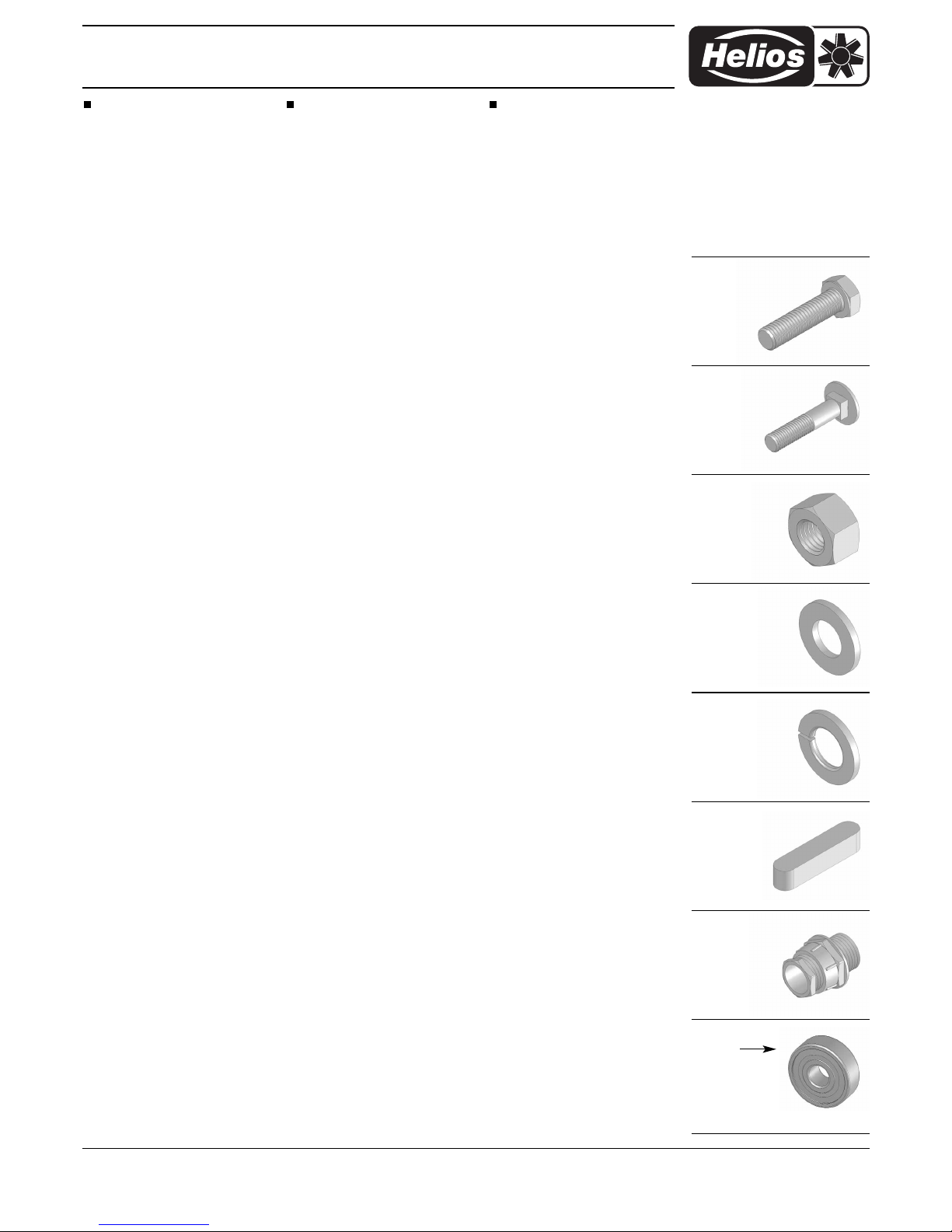
4.0 Normteile
Normteile sind nach Muster oder An-
gabe im freien Handel zu beziehen.
4.0 Standard parts
Standard parts can be produced ac-
cording to samples from local dealers.
4.0 Pièces normalisées
On se procurera les pièces norma-
lisées dans le commerce à l’aide d’un
échantillon
4.1
DIN 933
4.2
DIN 603
4.3
DIN 934
4.4
DIN 125
4.5
DIN 128
4.6
DIN 6885
4.7
DIN 46320
3.5
Lagertyp:
Type of bearing:
Type de roulement:
DIN 625
Service und Information
DHELIOS Ventilatoren GmbH & Co · Lupfenstraße 8 · 78056 VS-Schwenningen FHELIOS Ventilateurs · Z.I. La Fosse à la Barbière · 2, rue Louis Saillant · 93605 Aulnay sous Bois Cedex
CH HELIOS Ventilatoren AG · Steinackerstraße 36 · 8902 Urdorf/ Zürich GB HELIOS Ventilation Systems Ltd. · 5 Crown Gate · Wyncolls Road · Severalls Industrial Park ·
AHELIOS Ventilatoren · Postfach 854 · Siemensstraße 15 · 6023 Innsbruck Colchester · Essex · CO4 9HZ
Table of contents
Popular Automobile Accessories manuals by other brands

TIE DOWN
TIE DOWN LONGRUN 86103 Assembly/installation instructions

Belkin
Belkin TuneBase F8Z442 user manual

Whelen Engineering Company
Whelen Engineering Company RB6P installation guide

Prorack
Prorack K419 Fitting instructions

GTW MACH
GTW MACH 01-176 installation instructions

ClimAir
ClimAir SunnyBoy 10132-abc installation instructions


Whispbar
Whispbar K716W instructions

SHOCKERHITCH
SHOCKERHITCH AIR EQUALIZER Setup instructions

ADAPT SOLUTIONS
ADAPT SOLUTIONS LINK LK-SILC14L installation manual

Lund Industries
Lund Industries FE-CSMTS installation instructions

Prorack
Prorack K449 Fitting instructions

ICI
ICI 840121412906 Installation & use