ADAPT SOLUTIONS LINK LK-SILC14L User manual

LINK
INSTALLATION MANUAL
LK-SILC14L
Silverado | Suburban | Tahoe | Sierra | Yukon | Escalade
2014 & 2018
DRIVER SIDE FRONT

46
3
2
12
11
10
13 8
7
17
16
20
2
9
5
1
14
21
23
15
1 of 4
22
19
18
24
ITEM
PART NUMBER
QTY
DESCRIPTION
1
LK000L-02
1
Long Model LINK -Left-
2
LK-UNI-002L
1
002 Assembly Top Bearing Plate -Left-
3
PRD 333-107
4
Nylon Insert Locknut 5/16-18
4
LK-SILC14L-03
1
Seat Adapter -Left-
5
L-LK912
1
Communication Cable Support
6
PRD 339-136P
4
Socket Shoulder Screw Zinc Plated 3/8 x 1/2 x 5/16-
18 THD
7
LK710B
1
Chain Covert -Black-
8
PRD 110-106
2
Round washer head tapping screw #8 x 3/4
9
LK750LB
1
Pivot Cover -Left- Black
10
LK730LB
1
Outside Cover -Left- Black
11
LK731LB
1
Intside Cover -Left- Black
12
PRD 251-177
4
Trim Panel Clip Ø1/4'' x 3/4'' Black
13
LK700B
1
Link Covert -Black-
14
LK720LB
1
Pivot Motor Cover -Left- Black
15
LK960
1
LINK Wired Control
16
LK-SILC14L-01
1
Outside Floor Adapter -Left-
17
LK-SILC14L-02
1
Inside Floor Adapter -Left-
18
LK-SILC14-04
2
Seat Fixing
19
LK-SILC14-BK
1
Bolt Kit
20
LK-SILC14LB-05
1
Floor Adapter Trim -Left- Black
21
LK-SILC14LB-11
1
Seat Trim -Left- Black
22
LK-SILC14L-AB
1
Air Bag Link Kit -Left-
23
EW-CK-00
1
12V Power Supply Wiring Kit
24
LK-UNI-650
1
Manual Backup Tool Kit
LK-SILC14L
ADAPT SOLUTIONS
|[email protected]|866.641.0419|418.889.9838 fax
PART NUMBER
LINK Chevrolet Silverado Crew Cab 2014 & Up -Left-
DESCRIPTION
LINK CHEVROLET SILVERADO CREW CAB 2014 & Up

9
7
10
11
13
12
14
3
4
8
6
2
6
1
9
5
2 of 4
ITEM
PART NUMBER
QTY
DESCRIPTION
1
LK000L-02
1
Long Model LINK -Left-
2
LK-UNI-302L
1
002 Top Bearing Plate -Left-
3
LK-UNI-402
1
402 Cam Pusher
4
LK-UNI-502L
1
502L Pusher Frame
5
PRD 192-135
1
Spring Tension Pin 5/32 x 3/4
6
PRD 192-141
2
Spring Tensions Pin 3/16 x 3/4
7
PRD 192-151
1
Spring Tension Pin 1/4 x 3/4
8
PRD 333-107
1
Nylon Insert Locknut 5/16-18
9
PRD 337-213P
3
Button head socket cap screw Zinc Plated 5/16-18 x 3/4
10
PRD 339-116P
1
Socket Shoulder Screw Zinc Plated 5/16 x 1/2 x 1/4-20 THD
11
PRD 339-135P
1
Socket Shoulder Screw Zinc Plated 3/8 x 3/8 x 5/16-18 THD
12
SN 654-006
1
Nylon Spacer id .317" od .500"
13
SN 654-007
1
Nylon Spacer id .375" od .625"
14
SN 681-129
1
Wave Disc Spring 0.325 id x 0.546 od x 0.007 thickness
LK-SILC14L
ADAPT SOLUTIONS
|[email protected]|866.641.0419|418.889.9838 fax
PART NUMBER
LINK Chevrolet Silverado Crew Cab 2014 & Up -Left-
DESCRIPTION
LINK CHEVROLET SILVERADO CREW CAB 2014 & Up

1
11
12
7
6
10
5
4
8 3
9
2
3 of 4
ITEM
PART NUMBER
QTE
DESCRIPTION
1
LK-SILC14L-03
1
Seat Adapter -Left-
2
LK-SILC14-04
2
Seat Fixing
3
LK710B
1
Chain Covert -Black-
4
LK730LB
1
Outside Cover -Left- Black
5
LK731LB
1
Intside Cover -Left- Black
6
LK750LB
1
Pivot Cover -Left- Black
7
L-LK912
1
Communication Cable Support
8
PRD 110-106
2
Round washer head tapping screw #8 x 3/4
9
PRD 130-110
4
Slotted Hexagon Washer Head Tapping Screw #8 x 3/4
10
PRD 251-177
4
Trim Panel Clip Ø1/4'' x 3/4'' Black
11
PRD 333-107
4
Nylon Insert Locknut 5/16-18
12
PRD 339-136P
4
Socket Shoulder Screw Zinc Plated 3/8 x 1/2 x 5/16-18 THD
LK-SILC14L
ADAPT SOLUTIONS
|[email protected]|866.641.0419|418.889.9838 fax
PART NUMBER
LINK Chevrolet Silverado Crew Cab 2014 & Up -Left-
DESCRIPTION
LINK CHEVROLET SILVERADO CREW CAB 2014 & Up

6
2
1
3
4 of 4
4
7
10
10
12
13
14
5
9
8
11
ITEM
PART NUMBER
QTY
DESCRIPTION
1
LK-SILC14L-01
1
Outside Floor Adapter -Left-
2
LK-SILC14L-02
1
Inside Floor Adapter -Left-
3
LK-SILC14LB-05
1
Floor Adapter Trim -Left- Black
4
LK-SILC14LB-11
1
Seat Trim -Left- Black
5
LK-SILC14L-AB
1
Air Bag Link Kit -Left-
6
LK700B
1
Link Covert -Black-
7
LK720LB
1
Pivot Motor Cover -Left- Black
8
LK960
1
LINK Wired Control
9
EW-CK-00
1
12V Power Supply Wiring Kit
10
L-LK-UNI-250
2
Fixing Spacer
11
LK-UNI-650
1
Manual Backup Tool Kit
12
PRD 332-164P
4
Socket Head Cap Screw Zinc Plated 3/8-16 x 7/8
13
PRD 332-166P
4
Socket Head Cap Screw Zinc Plated 3/8-16 x 1 1/4
14
PRD 22136
1
Flat Socket Cap Screw M10-1.25 x 40mm G10.9
LK-SILC14L
ADAPT SOLUTIONS
|[email protected]|866.641.0419|418.889.9838 fax
PART NUMBER
LINK Chevrolet Silverado Crew Cab 2014 & Up -Left-
DESCRIPTION
LINK CHEVROLET SILVERADO CREW CAB 2014 & Up

LINK Silverado|Suburban|Tahoe|Sierra|Yukon|Escalade 2014 & 2018 |Driver FRONT p. 2
WARNINGS
PLEASE REVIEW BEFORE STARTING THE INSTALLATION
Look through the entire manual to understand the installation process.
Watch the tutorial videos that are found on the tablet.
During the installation use the ‘BYPASS’ mode to move the LINK.
Do not use the pendant or ‘PENDANT’ mode until you have reset the home position.
The LINK is designed to ALWAYS use the original seat. The biggest challenge this will present for the installer will
be extending the vehicle’s original seat wire harness, as this MUST be done. The general process does not vary, but
the exact steps will vary due to the trim level, the model and seat options from the vehicle manufacturer. Keeping
this in mind, we have made an effort to clearly describe the process required in this manual. However, it is possible
that the pictures in this manual do not match exactly the specific vehicle you are working on.
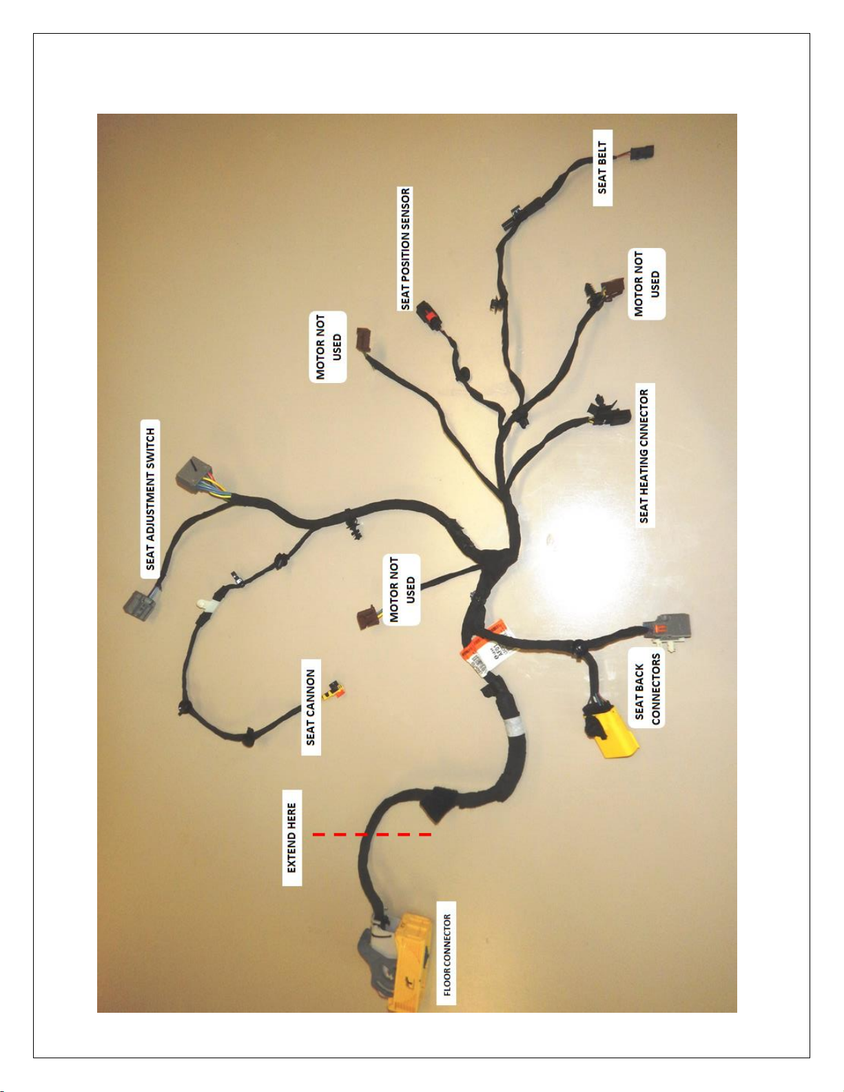
SEAT WIRING EXTENSION PROCESS
The wiring must be extended 80 inches. This extension is placed near the seat connectors that are under the seat.
The extension (80 inches) then passes under the LINK and loops around the back of the OEM seat –allowing the
seat and the LINK to travel in and out of the vehicle. Depending on the make, model and seat options, there are
components that must be disconnected, bypassed and/or relocated. On vehicle models with a seat position
memory function, the forward/backward, tilt and height adjustments as well as seat memory are replaced by the
LINK. However, the seat recline function is retained. (EXAMPLE: In the Ford F150, 2009-2014 model; the seat
height, tilt, forward and backward adjustment motors are disconnected and removed with the seat frame, but the
recline motor is retained. The control and memory box are relocated to the floor under the seat, next to the seat
connectors. The seat position sensor is also relocated to the floor under the seat. The wiring harness is then
extended from this point under the seat.)
PLEASE NOTE: If the ignition is turned on while extending a wire harness that includes airbags, this may cause the
airbag light to stay on following the installation.
ADAPT SOLUTIONS CANNOT BE HELD RESPONSIBLE FOR FAULTY WIRE EXTENSIONS.
Please use caution during the installation.
ANDROID TABLET –LINK I.T. SOFTWARE
If this is your first installation of a LINK, you will have also purchased an Android tablet that is required for the
installation and maintenance of the LINK product. This tablet will have the LINK IT software already installed.
We have prepared quick, easy and to the point tutorial videos imbedded into the software. Take a moment and
watch the video that shows all the features of the tablet. To do this, open the LINK IT app and tap on ‘INFO’.
Make sure your volume is turned up and tap on App-101. The video will start automatically.
REDUCED POWER MODE
A safeguard is integrated in the LINK system. Following any changes to the preset or sequence of the LINK, the
unit will enter a reduced power mode. This is to allow you to visually inspect the movements of the LINK to ensure
it is not damaging the vehicle or itself during its first cycle. On the tablet, a yellow bar will appear at the top of the
screen to indicate you are in reduced power mode. To exit, simply run the LINK a full cycle. NOTE:It is possible
that the LINK will stop during this cycle as power is reduced. Visually confirm nothing is impeding the movements
and then simply press the IN or OUT button again to continue the cycle. During the installation, if the 12V power is
removed and replaced at the same time as the 9V battery (LINK memory back up) is unplugged or fully drained,
the LINK will enter reduced power mode. Simply run a full cycle to exit. PLEASE NOTE: You will find an explanation
of this mode on a YELLOW tag attached to the hand pendant. Please explain the functions of the reduced power
mode to the LINK user (your client).
For technical support call 866.641.0419 or email tech@adaptsolutions.com
Please have the serial number of the unit on hand before placing your call.

LINK Silverado|Suburban|Tahoe|Sierra|Yukon|Escalade 2014 & 2018 |Driver FRONT p. 3
BEFORE STARTING THE INSTALLATION:
Make sure the steering wheel adjustment is fully UP and IN to allow maximum clearance for the driver
seat. When installing the LINK with hand controls, hand controls should be installed after the LINK.
1. Remove the driver side OEM seat and place it on a workbench or table. To do this, start by
disconnecting the seat belt from the side of the seat. Then, remove the four OEM bolts; two at the
rear of the seat and two at the front of the seat. Then, unplug the seat wire harness from the floor
connector.

LINK Silverado|Suburban|Tahoe|Sierra|Yukon|Escalade 2014 & 2018 |Driver FRONT p. 4
2. Remove all the plastic trims off both sides of the seat.
3. Disconnect and remove the seat belt pre-tensioner, and the seat belt receiver from either side of
the seat.

LINK Silverado|Suburban|Tahoe|Sierra|Yukon|Escalade 2014 & 2018 |Driver FRONT p. 5
4. Unbolt the seat back from the seat base. To do this, disconnect the seat back wiring connectors and
remove the hooks that keep the fabric flap in place. Then, remove the bolts on either side to
remove the seat back.
5. Now, remove the seat cushion from the seat base. To do this, remove the clips that hold the fabric
and the cushion onto the seat base.

LINK Silverado|Suburban|Tahoe|Sierra|Yukon|Escalade 2014 & 2018 |Driver FRONT p. 6
6. Remove the wire cushion support, (on some models the support is made of plastic) and the seat
pan. Be sure to detach the wire harness from the seat pan. NOTE: In some models, the seat pan is
spot welded onto the seat base. If this is the case, use a drill to remove the 6 spot welds to free the
seat pan from the base.
7. In models with ventilated seats, remove the fan from the wire cushion support. The Fan cannot be
reinstalled.

LINK Silverado|Suburban|Tahoe|Sierra|Yukon|Escalade 2014 & 2018 |Driver FRONT p. 7
8. Remove the wiring harness from the seat base.
9. Remove the seat trim support from the left side of the seat base, it will be reinstalled on to the
LINK seat adapter.

LINK Silverado|Suburban|Tahoe|Sierra|Yukon|Escalade 2014 & 2018 |Driver FRONT p. 8
10. Remove the seat position sensor from the seat base. Install it onto the provided bracket, # LK-
SILC14L-06. Plug the seat position sensor back into the wiring harness.
11. Run the power from the battery to the LINK. To do this, thread the red power cable (+) under the
doorstep molding and through the firewall. Make sure you pass through a grommet in the firewall
to prevent the cable from chaffing. Install the circuit breaker near the battery and then connect the
battery to the circuit breaker. Attach the black ground wire (-) to the vehicle’s frame, under the
doorstep moulding using a self-tapping screw. Locate a spot where the sheet metal is doubled-up to
ensure a proper ground.

LINK Silverado|Suburban|Tahoe|Sierra|Yukon|Escalade 2014 & 2018 |Driver FRONT p. 9
12. The wiring harness extension can now be made using the provided multibrand cable. Extend the OEM wire
harness with the provided connectors and 18 gauge multi strand extension. For best results, extend one
wire at a time. Test continuity of each wire through the extension to avoid errors. (If you wish to keep a
record of your wire extensions for reference, you will find a lined sheet at the very end of this manual for that
purpose.) The wiring extension will be routed out of the bottom left hand corner of the seat. Control box will
be relocated to the seat back.
2014 MODEL WITH CONTROL BOX BEFORE EXTENTION
LINK Silverado|Suburban|Tahoe|Sierra|Yukon|Escalade 2014 & 2018 |Driver FRONT p. 10
2018 MODEL, BEFORE WIRE EXTENTION

LINK Silverado|Suburban|Tahoe|Sierra|Yukon|Escalade 2014 & 2018 |Driver FRONT p. 11
2018 MODEL, AFTER EXTENTION

LINK Silverado|Suburban|Tahoe|Sierra|Yukon|Escalade 2014 & 2018 |Driver FRONT p. 12
13. Place the floor connector and the extended wire harness in the vehicle, on the floor before
installing the LINK floor adapters. (Do not plug in the floor connector at this time.) Part # LK-
SILC14L-01 installs towards the exterior of the vehicle, near the door. Tighten it in place with the
provided M10 X 40mm flat head bolt. Install part # LK-SILC14L-02 towards the interior or center of
the vehicle. Use the OEM bolt to secure it in place, but do not fully tighten it in place at this time.
14. Remove and modify the lower ‘B’ pillar trim using the provided stencil, then re-install.

LINK Silverado|Suburban|Tahoe|Sierra|Yukon|Escalade 2014 & 2018 |Driver FRONT p. 13
15. Connect auxiliary 12V power to the LINK and connect your Android tablet via Bluetooth. To do this,
turn on the Bluetooth function of your Android tablet and connect the Bluetooth module (small,
blue and white, 4 pronged connector) to the LINK pendant plug. Using the LINK IT application, go
to ‘BYPASS’. (If this is your first installation, please watch the tutorial that appears when you press
‘BYPASS’) Using the ‘BYPASS’ mode in the LINK IT app, press the ‘PIVOT OUTWARD’ button to
move the LINK out just enough to see the eight (8) bolt holes.
16. Place the LINK in the vehicle on the floor adapters. Use the four longer (3/8’’-16 x 1¼’’) socket cap
bolts to secure the LINK by the pivot, and use the four shorter (3/8’’-16 x 7/8’’) bolts to secure the
interior of the LINK. Be careful not to pinch the wire harness between the LINK and the floor
adapter. IMPORTANT: Run the LINK harness around and under the pivot. Do not run over the top
of the pivot as it can interfere with the function of the slide. Tighten the bolt on the inner floor
adapter. (# LK-SILC14L-02 ) Make sure the lower ‘B’ pillar shroud modification allows the LINK
pivot components to move freely.

LINK Silverado|Suburban|Tahoe|Sierra|Yukon|Escalade 2014 & 2018 |Driver FRONT p. 14
17. Connect the LINK to the vehicle’s 12V power supply. Using the ‘BYPASS’ mode on the tablet,
carefully use ‘PIVOT’ ‘TRAVEL’ and ’TILT’ to move the LINK out of the vehicle. Install the OEM wire
cushion support and seat pan onto the LINK seat adapter using the two provided ½’’x 1’’ x 3/8
shoulder bolts. Install the two brackets, parts # LK-SILC14-04 with the provided self-tapping screws
to fasten the seat pan to the LINK seat adapter. Re-install the seat cushion support.
18. Install the seat trim support onto the LINK seat adapter using the provided machine screws
and nuts.

LINK Silverado|Suburban|Tahoe|Sierra|Yukon|Escalade 2014 & 2018 |Driver FRONT p. 15
19. Place the seat wiring connectors near to the respective places, where they will be reconnected.
Route the wiring over the top of rear round tubing at the left hand side of the seat adaptor. If the
seat has a control box for the seat memory, it will have to be relocated, into the seatback.
20. Install the seatbelt receiver onto the LINK seat adapter using the provided 7/16-20 x 1’’ bolt, and
lock nut, place a washer on either side. Run the wiring to the plug of the extended harness and
reconnect it.
21. Install the seatbelt pre-tensioner to the seat adapter. Use the provided 7/16-20 x 2’’ bolt, and lock
nut. Pass the bolt through the pre-tensioner and place two washers as spacers. Install it onto the
seat adapter.

LINK Silverado|Suburban|Tahoe|Sierra|Yukon|Escalade 2014 & 2018 |Driver FRONT p. 16
22. If the vehicle is equipped with a fan in the seat base. The fan duct, in the seat cushion, must be
modified to allow clearance. Turn the seat cushion over and locate the fan duct in the seat cushion.
Trace around the outside of the vent. Remove the vent and cut out enough foam so that the vent is
embedded, and sits flush with the surface of the foam.
23. Next, install the seat cushion. In ‘BYPASS’ mode on the tablet, tilt the LINK up to allow access
for easier installation of the seat cushion.
Table of contents
Other ADAPT SOLUTIONS Automobile Accessories manuals

ADAPT SOLUTIONS
ADAPT SOLUTIONS XL-Seat XLS-DAKQ05R User manual

ADAPT SOLUTIONS
ADAPT SOLUTIONS XL-SEAT XLS-DAKC05L User manual

ADAPT SOLUTIONS
ADAPT SOLUTIONS SP-HDA18 User manual

ADAPT SOLUTIONS
ADAPT SOLUTIONS XL-SEAT XLS-COLX04R User manual

ADAPT SOLUTIONS
ADAPT SOLUTIONS Power-Pull User manual

ADAPT SOLUTIONS
ADAPT SOLUTIONS ASENTO EV-ACA17R User manual

ADAPT SOLUTIONS
ADAPT SOLUTIONS SPEEDY-LIFT SP-CHR17L User manual

ADAPT SOLUTIONS
ADAPT SOLUTIONS ASENTO EV-COLC15R User manual

ADAPT SOLUTIONS
ADAPT SOLUTIONS ASENTO EV-EXP18R User manual

ADAPT SOLUTIONS
ADAPT SOLUTIONS SPEEDY-LIFT SP-HDA05 User manual


