Helios Next 2 User manual
11
3100 28705-02
F
Apparecchio a LED con ottiche simmetriche rettangolari ed asimmetriche adatto per aree interne, esterne ed impianti
sportivi di medie dimensioni, con installazione mediante staffa, tramite montaggio a parete e su struttura metallica o
traversa.
LED luminaire with symmetric and asymmetric rectangular optics suitable for interior, exterior and sports facilities of small/
medium size, with bracket, wall, metal frame or crossbar mount.
Appareil à LED avec optiques symétriques rectangulaires et asymétriques adapté pour zones internes, externes et
installations sportives de petites/moyennes dimensions, avec installation au moyen d’étrier, par montage mural et sur
structure métallique ou traverse.
LED-Leuchte mit rechteckiger symmetrischer und asymmetrischer Optik für Innen- und Außenbereiche und mittelgroße
Sportanlagen, mit Installation über Halterung, Wandmontage und Metallrahmen oder Querträger.
NEXT 2-3-4-6/8 - CL. I
IP 66 - IK09
Peso massimo apparecchio: - Maximum weight of the appliance: - Poids maximum appareil: - Maximales Gewicht des Gerätes:
Next 2 5,7 Kg Next 3 6,3 Kg Next 4 7,8 Kg Next 6/8 13 Kg
Potenza massima apparecchio (LED + Driver): - Maximum power of the appliance (LED + Driver):
Puissance maximale appareil (LED + Driver): - Maximale Geräteleistung (LED + Driver):
Next 2 130W Next 3 162W Next 4 192W Next 6/8 400W
Altezze di installazione consigliate: da 5.0 a massimo 20.0 metri.
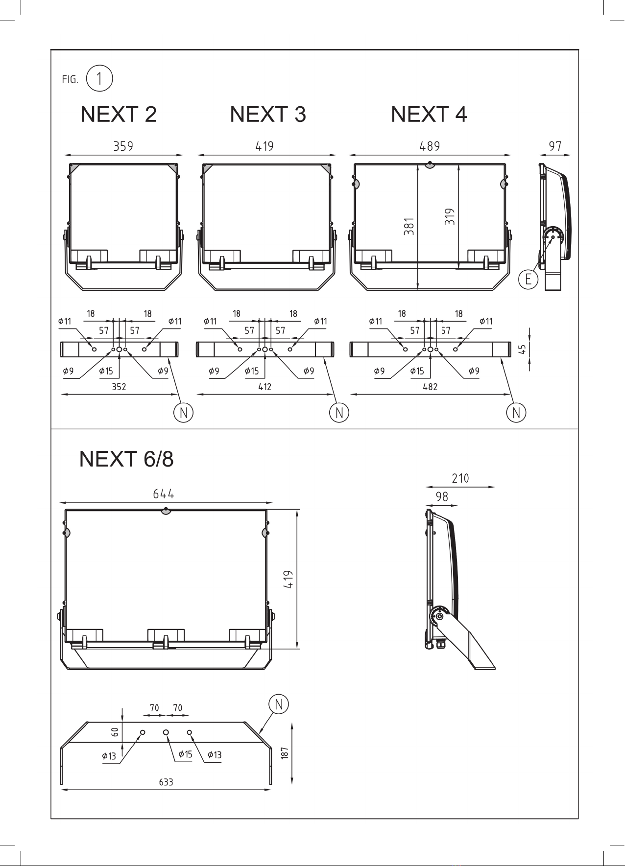
Tipologie, caratteristiche costruttive e ingombri degli apparecchi: vedere figura 1.
Supercie massima esposta al vento: vedere figura 2.
La distanza tra il proiettore e la supercie illuminata non deve essere inferiore a 1m: vedere figura 3.
Per garantire la sicurezza e l’integrità dell’apparecchio, attenersi fedelmente alle istruzioni sotto indicate.
Recommended installation height: from 5.0 up to 20.0 metres.
Type, constructional characteristics and size of the appliances; see figure 1.
Maximum surface area exposed to wind: check figure 2.
The distance between the oodlight and the illuminated surface must not exceed 1m: see figure 3.
Follow strictly the instructions below to ensure the safety degree and state of the appliance stay unchanged.
Hauteurs d’installation conseillées: de 5.0 à un maximum de 20.0 mètres.
Typologies, caractéristiques de construction et encombrements des appareils: voir figure 1.
Surface maximale exposée au vent: voir figure 2.
La distance entre le projecteur et la surface éclairée ne doit pas être inférieure à 1m: voir figure 3.
Pour garantir la sécurité et l’intégrité de l’appareil, veuillez respecter à la lettre les instructions indiquées ci-après.
Empfohlene Installationshöhe: von 5.0 bis maximal 20.0 Meter.
Typologien, bauliche Eigenschaften und Abmessungen der Geräte: siehe Abbildung 1.
Maximale freiliegende Windäche: siehe Abbildung 2.
Der Abstand zwischen dem Scheinwerfer und der beleuchteten Fläche muss mindestens 1m betragen: siehe Abbildung 3.
Um die Sicherheit und Integrität des Geräts zu gewährleisten, befolgen Sie bitte die nachstehenden Anweisungen.
2
3
Operating position: check the figure 4.
The appliance can be installed on normally
flammable surfaces provided that the distances
and aiming points shown in figures 6-7 are
respected.
Pay attention to the opening, for both versions,
because the glass is not connected to the body
of the luminaire.
The maximum thermal shock resistance of the
glass is 200°C.
Next 2-3-4-6/8 is fitted with a pressure
compensator filter made from Teflon.
During installation and before performing any
maintenance on the appliance, make sure it is
disconnected from the power supply.
To connect the bracket “N” (see figure 1) to the
body of the luminaire, tighten the screws “E”
(M10 for Next2-3-4 e M12 for Next6/8) to secure
the bracket (see figure 9) by applying a torque of
80Nm if M10 and 100Nm if M12.
To connect the bracket “N” (see figure 1) to
the metal frame or to the crossbar in case of
a through-hole, use an M10/12 bolt and flat or
toothed washers.
To install the floodlight on the wall, use at least
2 M10/12 screws and flat or toothed washers;
insert the screws in the holes available on the
bracket “N” (see figure 1).
To install the luminaire on horizontal surfaces
and in case of blind holes use at least 1 M10/12
screw in the middle to ensure the rotation of
the luminaire, and its relative flat and toothed
washer; use the holes available on the bracket
“N” (see figure 1).
Be sure to avoid operating appliances installed
externally during daylight hours to avoid
anomalous functioning of the electronic
components due to high environmental
temperatures.
Do not install the appliance near to heat sources
or in physical positions such as to exceed the
thermal limits of the appliance.
The projectors’ bodies feature 4 holes for
accessories (visors and protection grilles).
To install them, refer to the instructions for each
individual accessory.
The replacement of light sources can only be
performed by qualified personnel or by the
manufacturer of the device.
Any type of maintenance operation on the
components can only be performed by qualified
personnel or by the manufacturer of the
appliance.
Replace any damaged glass screens using
Fael spare parts only and, before closing the
projector, make sure that all the parts are in
their original position.
To ensure the proper and safe operation of the
luminaire, the installation operations must be
carried out by qualified personnel, following the
instructions herein.
Do not affix the light source while functioning.
Keep the instruction sheet after installation.
PHOTOBIOLOGICAL SAFETY according to the
standard IEC/TR62778:2014: Risk Group 1
Unlimited
“Applications of the 62471:2008 to light sources
and to lighting appliances for evaluation of the
risk of blue light”.
The appliance must be installed in such a
manner so that, in the case of direct illumination,
persons remaining for a prolonged time in the
vicinity of the light source are at a minimum
distance from the projector indicated in the table
set out below, named “threshold distance:Dthr”.
This threshold distance is calculated on the
basis of Standard IEC/TR 62778:2014 from
which it is possible to determine the minimum
IISTRUZIONI DI IMPIEGO
Posizioni di funzionamento: vedere figura 4.
L’apparecchio è adatto al montaggio su
superfici normalmente infiammabili rispettando
le distanze ed i puntamenti indicati nelle figure
6-7.
Prestare attenzione all’apertura, per entrambe le
versioni, il vetro è collegato alla parte inferiore
del corpo dell’ apparecchio.
La temperatura massima supportata dal vetro è
di 200°C.
L’apparecchio Next 2-3-4-6/8 è equipaggiato
con filtro di compensazione pressoria in teflon.
In fase di installazione e prima di eseguire
qualunque intervento di manutenzione
sull’apparecchio, accertarsi che sia disconnessa
l’alimentazione dell’apparecchio.
Per collegare la staffa “N” (vedere figura 1) al
corpo dell’apparecchio serrare a fondo le viti
“E” (M10 per Next2-3-4 e M12 per Next6/8)
per il serraggio della staffa (vedere figura 9)
applicando un momento torcente di 80Nm se
M10 e 100Nm se M12.
Per collegare la staffa “N” (vedere figura 1) alla
struttura metallica o alla traversa, in caso di foro
passante, utilizzare la soluzione con bullone
M10/12 e relative rondelle piane e dentate.
Per installare il proiettore amuro utilizzare
almeno 2 viti M10/12 e relative rondelle piane
e dentate, utilizzando i fori presenti sulla staffa
“N” (vedere figura 1).
Per installare l’apparecchio su superficie
orizzontale e foro cieco utilizzare almeno 1
vite M10/12 in posizione centrale, per rotazione
azimutale dell’apparecchio, e relativa rondella
piana e dentata, utilizzando i fori presenti sulla
staffa “N” (vedere figura 1).
Evitare in modo assoluto di far funzionare gli
apparecchi installati all’esterno durante le ore
diurne, per evitare funzionamenti anomali della
componentistica elettronica dovuti alle alte
temperature ambientali.
Non installare l’apparecchio vicino a fonti da
calore o in posizioni geometriche tali da superare
il limite termico dell’apparecchio.
I corpi dei proiettori sono predisposti di 4 fori
per il montaggio di accessori (visiere e griglie
di protezione). Per il montaggio degli stessi
fare riferimento alle istruzioni di ogni singolo
accessorio.
La sostituzione delle sorgenti luminose può
essere effettuata solo da personale qualificato
o dal costruttore dell’apparecchio.
Qualsiasi tipo di manutenzione alla
componentistica può essere effettuata solo
da personale qualificato o dal costruttore
dell’apparecchio.
Sostituire gli schermi di protezione in vetro
danneggiati, utilizzando esclusivamente
ricambi Fael e verificare, prima della chiusura
dell’apparecchio, che tutti i componenti siano
nella loro posizione originale.
Per garantire il buon funzionamento e la
sicurezza dell’apparecchio, l’installazione deve
essere eseguita da
personale qualificato che si deve attenere
scrupolosamente alle istruzioni ivi riportate.
Non fissare la sorgente luminosa durante il
funzionamento.
Una volta terminata l’installazione, conservare il
foglio di istruzioni.
SICUREZZA FOTOBIOLOGICA secondo la
norma IEC/TR62778:2014: Risk Group 1
Unlimited
“Applicazione della 62471:2008 alle sorgenti
luminose e agli apparecchi di illuminazione per
la valutazione del rischio della luce blu”.
L’apparecchio deve essere installato in modo
tale che, nel caso di illuminazione diretta, le
persone che sostano in modo prolungato in
prossimità del corpo illuminante, siano ad una
distanza minima dal proiettore indicata nella
tabella sotto riportata e denominata “distanza
di soglia:Dthr”.Tale distanza di soglia è calcolata
in base alla norma IEC/TR 62778:2014 tramite
la quale è possibile determinare la distanza
GB INSTRUCTIONS FOR USE FINSTRUCTIONS D’EMPLOI DANWEISUNGEN FÜR DIE
VERWENDUNG
Positions de fonctionnement: voir figure 4.
L’appareil est adapté pour être monté sur
des surfaces normalement inflammables
en respectant les distances et les pointages
indiqués dans les figures 6-7.
Prenez soin lors de l’ouverture, dans les deux
versions, étant donné que le verre n’est pas relié
au corps de l’appareil.
La température maximale supportée par le verre
est de 200°C.
L’appareil Next 2-3-4-6/8 est équipé de filtre de
compensation de pression en téflon.
En phase d’installation et avant d’effectuer
une quelconque intervention d’entretien sur
l’appareil, assurez-vous que l’alimentation de
l’appareil est bien déconnectée.
Pour connecter l’étrier “N” (voir figure 1) au
corps de l’appareil, serrer à fond les vis “E”
(M10 pour Next2-3-4 et M12 pour Next6 / 8)
pour serrer l’étrier (voir figure 9) en appliquant
un moment de torsion de 80 Nm si M10 et 100
Nm si M12.
Pour fixer l’étrier “N” (voir figure 1) à la
structure métallique ou à la traverse, en cas
de trou passant, utiliser la solution avec boulon
M10/12 et leurs rondelles plates et dentées.
Pour installer le projecteur au mur, utiliser au
moins 2 vis M10/12 et leurs rondelles plates et
dentées relatives, en utilisant les trous présents
sur l’étrier “N” (voir figure 1).
Pour installer l’appareil sur des surfaces
horizontales et trou borgne, utiliser au moins 1
vis M10/12 en position centrale, pour rotation
azimutale de l’appareil, et sa rondelle plate et
dentée, en utilisant les trous présents sur l’étrier
“N” (voir figure 1).
Éviter absolument de faire fonctionner les
appareils installés à l’extérieur durant les
heures du jour, afin d’éviter des fonctionnements
anormaux des composants électroniques dus à
des températures ambiantes élevées.
Ne pas installer l’appareil près de sources de
chaleur ou dans des positions géométriques qui
font dépasser la limite thermique de l’appareil.
Les corps des projecteurs sont pourvus de 4
trous pour le montage des accessoires (visières
et grilles de protection).
Pour leur montage, vous référer aux instructions
de chacun des accessoires.
Le remplacement des sources lumineuses peut
être effectué uniquement par un personnel
qualifié ou par le fabricant de l’appareil.
Seul des personnes qualifiées ou le Fabricant
sont autorisés à intervenir pour la maintenance
de l’appareil.
Remplacer les écrans de protection en verre
endommagés en utilisant exclusivement des
pièces de rechange Fael et, avant de fermer
l’appareil, vérifier que tous les composants se
trouvent bien dans leur position d’origine.
Afin de garantir le bon fonctionnement et la
sécurité de l’appareil, l’installation doit être
effectuée par un personnel qualifié qui doit
respecter scrupuleusement les instructions qui
y sont reportées.
Ne pas fixer la source lumineuse durant le
fonctionnement.
Au terme de l’installation, conserver le feuillet
d’instructions.
SÉCURITÉ PHOTOBIOLOGIQUE selon la norme
IEC/TR62778:2014: Risk Group 1 Unlimited
“Application de la 62471:2008 aux sources
lumineuses et aux appareils d’éclairage pour
l’évaluation du risque de la lumière bleue”.
L’appareil doit être installé afin que, dans le cas
d’éclairage direct, les personnes stationnant de
façon prolongée près du corps d’éclairage se
trouvent à une distance minimale du projecteur
indiquée dans le tableau reporté ci-dessous et
appelée “distance de seuil: Dthr”.
Cette distance de seuil est calculée sur la
base de la norme IEC/TR 62778:2014 laquelle
permet de déterminer la distance minimale
entre les sources lumineuses et les yeux d’un
observateur.
Arbeitspositionen: siehe Abbildung 4.
Das Gerät eignet sich für die Montage auf
normalerweise entflammbaren Oberflächen
unter Beachtung Abstände und Punkte, die in
den Abbildungen 6-7 angegeben sind.
Bei beiden Versionen auf die Öffnung achten, da
das Glas nicht am Gerätegehäuse angeschlossen
ist.
Die maximale Temperatur, die vom Glas
getragen wird, beträgt 200°C.
Das Gerät Next 2-3-4-6/8 1 ist mit einem Teflon-
Druckausgleichsfilter ausgestattet.
Vergewissern Sie sich während der Installation
und vor Wartungsarbeiten am Gerät, dass das
Gerät nicht angeschlossen ist.
Zur Verbindung der Halterung “N” (siehe
Abbildung 1) am Gehäuse des Gerätes, die
Schrauben “E” (M10 für Next2-3-4 und M12 für
Next6/8) für den Anzug der Halterung vollständig
(siehe Abbildung 9) mit einem Drehmoment von
80Nm ist M10 und 100Nm ist M12. festziehen.
Zur Verbindung der Halterung “N” (siehe
Abbildung 1) an der Metallstruktur oder am
Querträger, im Falle eines Durchgangsloch, die
Lösung mit Schraube M8 und die dazugehörigen
flachen und verzahnten Unterlegscheiben
verwenden.
Zur Installation des Scheinwerfers an der
Wand mindestens 2 Schrauben M8 und
die dazugehörigen flachen und verzahnten
Unterlegscheiben verwenden, dazu das Loch an
der Halterung “N” nutzen (siehe Abbildung 1).
Zur Installation des Gerätes auf einer horizontalen
Fläche und Sackloch, mindestens 1 Schraube M8
in mittlerer Position für die azimutale Drehung
des Gerätes und die dazugehörige flache und
gezahnte Unterlegscheibe verwenden, dazu
das Loch an der Halterung “N” nutzen (siehe
Abbildung 1).
Den Betrieb der im Freien installierten
Geräte während der Tageslichtstunden
unbedingt vermeiden, um Störungen der
elektronischen Komponenten aufgrund hoher
Umgebungstemperaturen zu vermeiden.
Installieren Sie das Gerät nicht in der Nähe
von Wärmequellen oder in geometrischen
Positionen, um die thermische Grenze des
Geräts zu überwinden.
Die Scheinwerfergehäuse haben 4 Löcher
für die Montage von Zubehör (Blenden und
Schutzgitter). Informationen zur Montage finden
Sie in den Anweisungen zu den einzelnen
Zubehörteilen.
Der Austausch der Lichtquellen darf nur von
qualifiziertem Personal oder vom Hersteller des
Geräts durchgeführt werden.
Die Wartungsarbeiten an den Komponenten
darf nur von qualifiziertem Personal oder vom
Hersteller des Geräts durchgeführt werden.
Ersetzen Sie beschädigte Glasabschirmungen
nur mit Ersatzteilen von Fael und überprüfen Sie,
ob sich alle Komponenten in ihrer ursprünglichen
Position befinden, bevor Sie das Gerät schließen.
Um die ordnungsgemäße Funktion und
Sicherheit des Geräts zu gewährleisten, muss
die Installation von
qualifiziertem Personal durchgeführt werden,
das die hier angegebenen Anweisungen
befolgen muss.
Bringen Sie die Lichtquelle während des Betriebs
nicht an.
Wenn die Installation abgeschlossen ist,
bewahren Sie die Anweisungen auf.
PHOTOBIOLOGISCHE SICHERHEIT gemäß
der Norm IEC/TR62778:2014: Risk Group 1
Unlimited
“Umsetzung der Richtlinie 62471:2008 in Bezug
auf Lichtquellen und Beleuchtungskörper zur
Risikobeurteilung von Blaulicht“. Das Gerät
muss so installiert werden, dass bei direkter
Beleuchtung Personen, die sich längere Zeit in
der Nähe des Beleuchtungskörpers aufhalten,
einen Mindestabstand zum Scheinwerfer haben,
der in der folgenden Tabelle angegeben ist und
als “Schwellenabstand: Dthr” bezeichnet wird”.

4

5
6
minima tra le sorgenti luminose e gli occhi
dell’osservatore. Tale distanza è in funzione della
distribuzione fotometrica dell’apparecchio, e
della temperatura di colore della sorgente a LED.
Distanza sicurezza fotobiologica: vedere figura
26.
ATTENZIONE: tale distanza non deve essere
intesa come altezza di installazione.
Si consiglia un’altezza minima, rispetto ai
corpi illuminati, uguale alla distanza di soglia
fotobiologica per gli apparecchi simmetrici.
In caso di apparecchi asimmetrici, fare
riferimento alla figura 26.
COLLEGAMENTO ELETTRICO NEXT VERSIONE
FISSA O 1-10V ESECUZIONE CL. I
A seconda della versione vedere immagine di
riferimento corrispondente:
• NEXT 2 Collegamento elettrico 1-10V CL. I
(vedere figura 16);
• NEXT 3 Collegamento elettrico 1-10V CL. I
(vedere figura 18);
• NEXT 4 Collegamento elettrico 1-10V CL. I
(vedere figura 20);
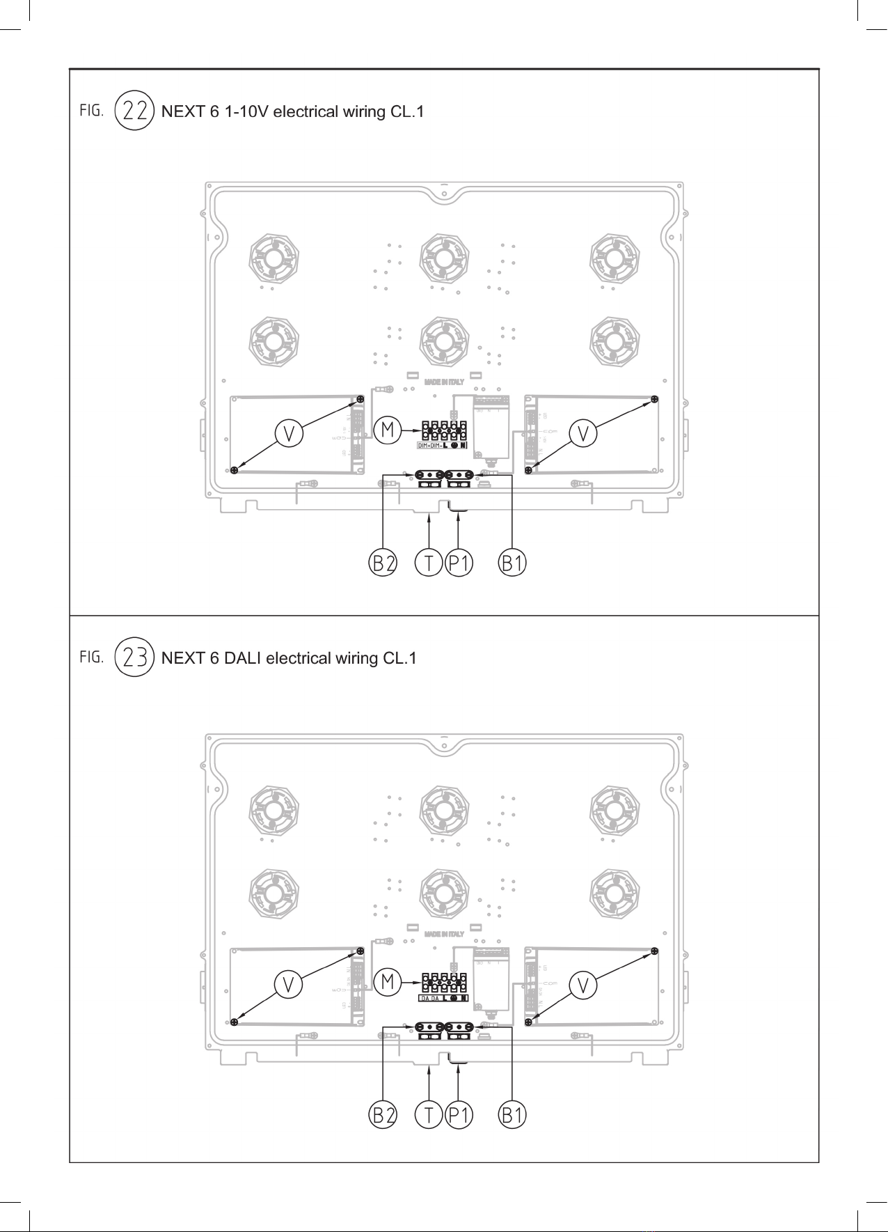
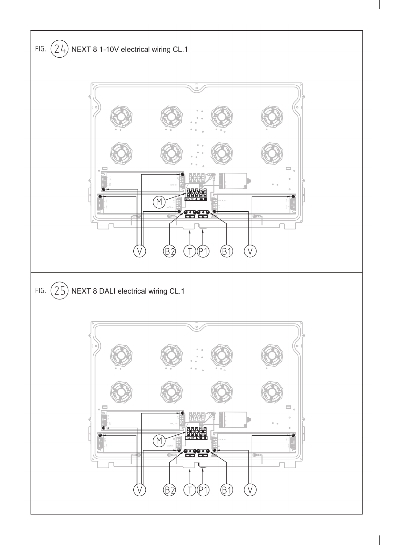
• NEXT 6/8 Collegamento elettrico 1-10V CL. I
(vedere figura 22);
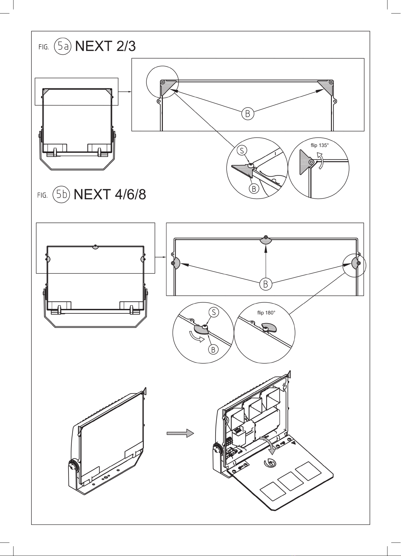
Per accedere alla parte interna dell’apparecchio
allentare le viti “S” fino a consentire la rotazione
di 135° o 180° (a seconda della versione
di apparecchio in dotazione) delle piastrine
fermavetro “B” che fissano il vetro “A” e
serrarle in posizione in modo che non intralcino
l’apertura del vetro. Sollevare quindi cautamente
il vetro nella parte superiore.
(vedere figura 5a o 5b).
Prestare attenzione all’apertura, il vetro si apre
con un’angolazione massima di circa 100°.
Versione con cavo di alimentazione separato
da eventuale cavo 1-10V
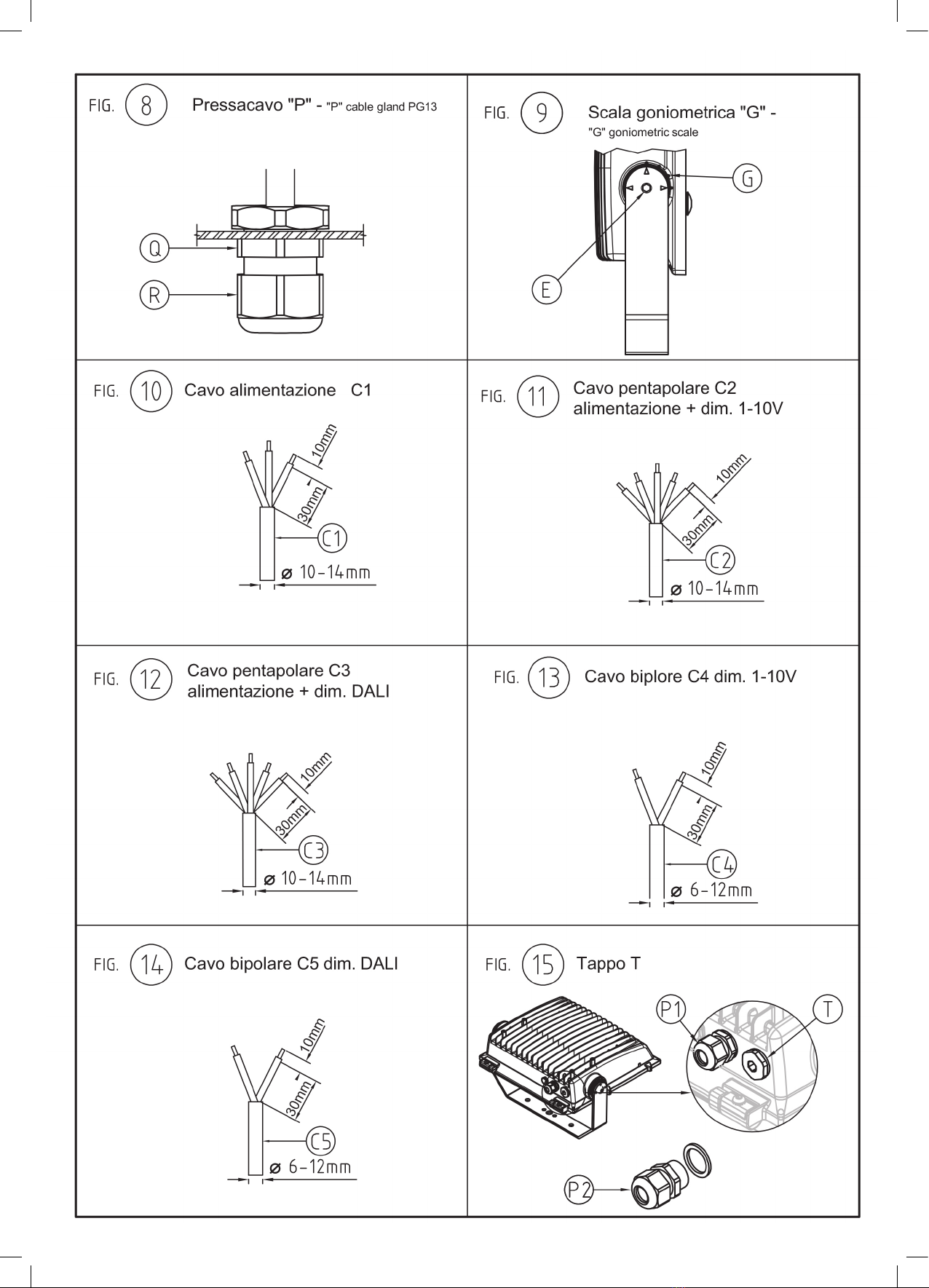
Far passare il cavo di alimentazione tripolare
“C1” (Fase, Neutro, Terra, vedere figura 10)
attraverso il pressacavo “P1” e sotto il serracavo
“B1”.
Collegare i conduttori ai poli L, N e Terra del
morsetto “M”.
Serrare il serracavo “B1” applicando un
momento torcente di 1.0Nm.
In caso di presenza cavo 1-10V:
Rimuovere il tappo “T” dal corpo dell’apparecchio
(vedere figura 15).
Montare il pressacavo “P2” presente nel
sacchetto fornito da FAEL.
Far passare il cavo di controllo 1-10V bipolare
“C4” (vedere figura 13) attraverso il pressacavo
“P2”, sotto il serracavo “B2” e collegarlo ai poli
DIM +, DIM - del morsetto “M” rispettando le
polarità.
Serrare il serracavo “B2” applicando un
momento torcente di 1.0Nm.
Versione con cavo di alimentazione + cavo
1-10V pentapolare
Far passare il cavo di alimentazione + cavo
1-10V pentapolare “C2” (Fase, Neutro,
Terra, 1-10V, vedere figura 11) attraverso il
pressacavo “P1” e sotto il serracavo “B1”.
Collegare i conduttori di Fase, Neutro e Terra ai
poli L, N e Terra del morsetto “M” e i conduttori
di controllo 1-10V ai poli DIM +, DIM - del
morsetto “M” rispettando le polarità.
Serrare il serracavo “B1” applicando un
momento torcente di 1.0Nm.
COLLEGAMENTO ELETTRICO NEXT VERSIONE
DALI ESECUZIONE CL. I
A seconda della versione vedere immagine di
riferimento corrispondente:
• NEXT 2 Collegamento elettrico DALI CL. I
(vedere figura 17);
• NEXT 3 Collegamento elettrico DALI CL. I
(vedere figura 19);
• NEXT 4 Collegamento elettrico DALI CL. I
(vedere figura 21);
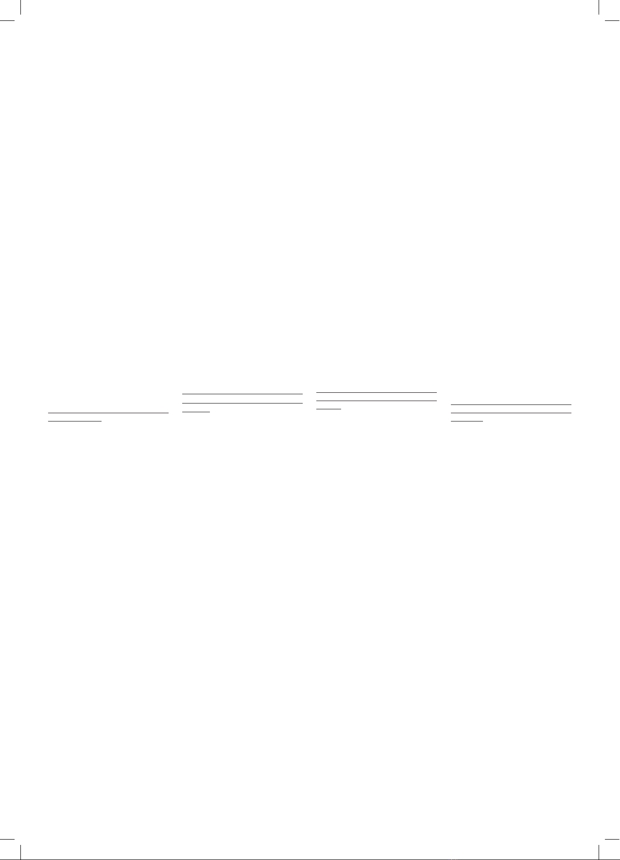
• NEXT 6/8 Collegamento elettrico DALI CL. I
(vedere figura 23);
Per accedere alla parte interna dell’apparecchio
allentare le viti “S” fino a consentire la rotazione
di 135° o 180° (a seconda della versione
di apparecchio in dotazione) delle piastrine
fermavetro “B” che fissano il vetro “A” e
serrarle in posizione in modo che non intralcino
l’apertura del vetro. Sollevare quindi cautamente
distance between the light sources and the eye
of the observer. This distance is a function of the
photometric distribution of the appliance, and of
the colour temperature of the LED source.
Photobiological safety distance: see figure 26.
ATTENTION: this distance must not be
understood as installation height.
We recommend a minimum height, compared to
illuminated bodies, equal to the photobiological
threshold distance for symmetrical luminaires.
In the case of asymmetric luminaires, refer to
figure 26.
ELECTRICAL CONNECTION NEXT VERSION
1-10V EXECUTION CL. I
Depending on the version, see the corresponding
reference image:
• NEXT 2 Electrical connection 1-10V CL. I
(see picture 16);
• NEXT 3 Electrical connection 1-10V CL. I
(see picture 18);
• NEXT 4 Electrical connection 1-10V CL. I
(see picture 20);
• NEXT 6/8 Electrical connection 1-10V CL. I
(see picture 22);
To access the inside of the luminaire, loosen the
“S” screws to enable a rotation by 135° or 180°
(depending on the luminaire version supplied) of
the glass fixing plates “B” that secure glass “A”
and tighten them in place so that they do not
hinder the opening of the glass. Then carefully
lift the glass from the top. (see figure 5a or 5b).
Pay attention to the opening, the glass opens at a
maximum angle of approximately 100°.
Version with power cord separate from 1-10V
cable
Pass the three-pole power supply cord
“C1”(Phase, Neutral, Ground; check the figure
10) through the cable gland “P1” and beneath
the cable clamp “B1”.
Connect the conductors to the L, N and Ground
poles of the terminal “M”.
Tighten the cable clamp “B1” by applying a
torque of 1.0Nm.
Remove the cap “T” from the body of the
luminaire (see figure 15).
Mount the cable gland “P2” in the bag provided
by FAEL.
Pass the two-pole 1-10V control cable “C4”
(check the figure 13) through the cable gland
“P2”, beneath the cable clamp “B2” and connect
it to the DIM +, DIM - poles of the terminal “M”;
make sure to observe the polarity.
Tighten the cable clamp “B2” by applying a
torque of 1.0Nm.
Version with power cord + cable 1-10V five-
pole
Pass the power cord + five-pole cable 1-10V
“C2“ (Phase, Neutral, Ground; 1-10V, check the
figure 11) through the cable gland “P1” and
beneath the cable clamp “B1”.
Connect the Phase, Neutral and Ground
conductors to the L, N and Ground poles of the
“M” clamp and the 1-10V control conductors
to the DIM+, DIM - poles of the “M” clamp,
observing the polarities.
Tighten the cable clamp “B1” by applying a
torque of 1.0Nm.
ELECTRICAL CONNECTION NEXT VERSION
DALI EXECUTION CL. I
Depending on the version, see the corresponding
reference image:
• NEXT 2 Electrical connection DALI CL. I
(see picture 17);
• NEXT 3 Electrical connection DALI CL. I
(see picture 19);
• NEXT 4 Electrical connection DALI CL. I
(see picture 21);
• NEXT 6/8 Electrical connection DALI CL. I
(see picture 23);
To access the inside of the luminaire, loosen the
“S” screws to enable a rotation by 135° or 180°
(depending on the luminaire version supplied) of
the glass fixing plates “B” that secure glass “A”
and tighten them in place so that they do not
Cette distance est fonction de la distribution
photométrique de l’appareil et de la température
de couleur de la source à LED.
Distance sécurité photobiologique: voir figure
26.
ATTENTION: cette distance ne doit pas être
considérée comme hauteur d’installation.
On conseille une hauteur minimum, par rapport
aux corps éclairés, égale à la distance de seuil
photobiologique pour les appareils symétriques.
Dans le cas d’appareils asymétriques, se référer
à la figure 26.
BRANCHEMENT ÉLECTRIQUE NEXT VERSION
1-10V EXÉCUTION CL. I
En fonction de la version, voir image
correspondante de référence:
• NEXT 2 Branchement électrique 1-10V CL. I
(voir figure 16);
• NEXT 2 Branchement électrique 1-10V CL. I
(voir figure 18);
• NEXT 2 Branchement électrique 1-10V CL. I
(voir figure 20);
• NEXT 6/8 Branchement électrique 1-10V
CL. I(voir figure 22);
Pour accéder à la partie interne de l’appareil,
desserrer les vis “S” pour permettre une rotation
de 135° ou de 180° (selon la version de l’appareil
en dotation) aux plaquettes de fixage du verre
“B” qui fixent le verre “A” et les serrer de façon à
ce qu’elles n’entravent pas l’ouverture du verre.
Puis soulever délicatement la partie supérieure
du verre. (voir figure 5a ou 5b).
Attention, lors de l’ouverture, l’angle maximum
du verre est d’environ 100°.
Version avec câble d’alimentation séparé du
câble 1-10V
Faire passer le câble d’alimentation tripolaire
“C1” (Phase, Neutre, Terre, voir figure 10 à
travers le pressecâble “P1” et sous le serre-
câbles “B1”.
Brancher les conducteurs aux pôles L, N et Terre
de la borne “M”.
Serrer le serre-câbles “B1” en appliquant un
moment de torsion de 1.0Nm.
Retirer le bouchon “T” du corps de l’appareil
(voir figure 15).
Monter le presse-câbles “P2” présent dans le
sachet fourni par FAEL.
Faire passer le câble de contrôle 1-10V bipolaire
“C4” (voir figure 13) à travers le presse-câbles
“P2”, sous le serre-câble “B2” et le brancher
aux pôles DIM +, DIM - de la borne “M” en
respectant les polarités.
Serrer le serre-câbles “B2” en appliquant un
moment de torsion de 1.0Nm.
Version avec câble d’alimentation + câble
1-10V pentapolaire
Faire passer le câble d’alimentation + câble
1-10V pentapolaire “C2” (Phase, Neutre, Terre,
1-10V, voir figure 11) à travers le presse-câbles
“P1” et sous le serre-câbles “B1”.
Brancher les conducteurs de Phase, Neutre et
Terre aux pôles L, N et Terre de la borne “M” et
les conducteurs de contrôle 1 1-10V aux pôles
DIM +, DIM - de la borne “M” en respectant les
polarités.
Serrer le serre-câbles “B1” en appliquant un
moment de torsion de 1.0Nm.
BRANCHEMENT ÉLECTRIQUE NEXT VERSION
DALI EXÉCUTION CL. I
En fonction de la version, voir image
correspondante de référence:
• NEXT 2 Branchement électrique DALI CL. I
(voir figure 17);
• NEXT 2 Branchement électrique DALI CL. I
(voir figure 19);
• NEXT 2 Branchement électrique DALI CL. I
(voir figure 21);
• NEXT 6/8 Branchement électrique DALI CL. I
(voir figure 23);
Pour accéder à la partie interne de l’appareil,
desserrer les vis “S” pour permettre une rotation
de 135° ou de 180° (selon la version de l’appareil
en dotation) aux plaquettes de fixage du verre
“B” qui fixent le verre “A” et les serrer de façon à
ce qu’elles n’entravent pas l’ouverture du verre.
Puis soulever délicatement la partie supérieure
du verre. (voir figure 5a ou 5b).
Attention, lors de l’ouverture, l’angle maximum
du verre est d’environ 100°.
Dieser Schwellenabstand wird gemäß der Norm
IEC/TR 62778:2014 berechnet, mit der es
möglich ist, den Mindestabstand zwischen den
Lichtquellen und den Augen des Betrachters
zu bestimmen. Dieser Abstand hängt von der
photometrischen Verteilung des Geräts und der
Farbtemperatur der LED-Quelle ab.
Photobiologischer Sicherheitsabstand: siehe
Abbildung 26.
ACHTUNG: Dieser Abstand darf nicht als
Installationshöhe verstanden werden. Es wird
eine Mindesthöhe zu Leuchtkörpern empfohlen,
die dem photobiologischen Schwellenabstand
für symmetrische Geräte entspricht. Bei
asymmetrischen Geräten, siehe Abbildung 26.
ELEKTRISCHER ANSCHLUSS NEXT VERSION
1-10V AUSFÜHRUNG CL. I
Je nach Version auf das entsprechende
Referenzbild Bezug nehmen:
• NEXT 2 Elektrisscher anschluss 1-10V CL. I
(siehe Abbildung 16);
• NEXT 3 Elektrisscher anschluss 1-10V CL. I
(siehe Abbildung 18);
• NEXT 4 Elektrisscher anschluss 1-10V CL. I
(siehe Abbildung 20);
• NEXT 6/8 Elektrisscher anschluss 1-10V
CL. I (siehe Abbildung 22);
Um Zugang zum Geräteinneren zu erhalten,
lösen Sie die Schrauben “S” um eine 135° oder
180° Drehung (je nach Version des gelieferten
Gerätes) der Glashalteplatten “B”, mit denen das
Glas “A” befestigt ist zu ermöglichen und ziehen
Sie sie in Position fest, um die Öffnung des
Glases nicht zu behindern. Dann vorsichtig das
Glas im oberen Teil anheben (siehe Abbildung
5a oder 5b). Auf die Öffnung achten, das Glas
öffnet sich mit einem maximalen Winkel von
ungefähr 100°.
Version mit Stromkabel getrennt vom Kabel
1-10V
Das dreipolige Stromkabel “C1” (Phase,
Neutral, Erdung, siehe Abbildung 10) durch
die Kabelverschraubung “P1” und unter dem
Kabelbaum “B1” durchführen. Die Leiter in
den Polen L, N und Erdung der Klemme “M”
einsetzen. Den Kabelbaum “B1” mit einem
Drehmoment von 1.0Nm anziehen. Den Deckel
“T” vom Gerätegehäuse entfernen (siehe
Abbildung 15). Die Kabeldurchführung “P2”
einbauen, die sich in der von FAEL gelieferten
Tüte befindet. Führen Sie das zweipolige
Steuerkabel 1-10V “C4” (siehe Abbildung 13)
durch die Kabelverschraubung “P2”, unter dem
Kabelbaum “B2” durch und schließen Sie es an
die Pole DIM +, DIM - der Klemme “M” an unter
Beachtung der Polarität. Den Kabelbaum “B2”
mit einem Drehmoment von 1.0Nm anziehen.
Version mit 5-poligem Stromkabel + Kabel
1-10V
Das 5-polige Stromkabel + Kabel 1-10V “C2”
(Phase, Neutral, Erdung, 1-10V, siehe Abbildung
11) durch die Kabelverschraubung “P1” und
unter dem Kabelbaum “B1” durchführen.
Die Leiter von Phase, Neutral und Erdung an
die Pole L, N und Erdung in der Klemme “M”
und die Leiter der Steuerung 1-10V an die Pole
DIM +, DIM - der Klemme “M” anschließen. Den
Kabelbaum “B1” mit einem Drehmoment von
1.0Nm anziehen.
ELEKTRISCHER ANSCHLUSS NEXT VERSION
DALI AUSFÜHRUNG CL. I
Je nach Version auf das entsprechende
Referenzbild Bezug nehmen:
• NEXT 2 Elektrisscher anschluss DALI CL. I
(siehe Abbildung 17);
• NEXT 3 Elektrisscher anschluss DALI CL. I
(siehe Abbildung 19);
• NEXT 4 Elektrisscher anschluss DALI CL. I
(siehe Abbildung 21);
• NEXT 6/8 Elektrisscher anschluss DALI CL. I
(siehe Abbildung 23);
Um Zugang zum Geräteinneren zu erhalten,
lösen Sie die Schrauben “S” um eine 135° oder
180° Drehung (je nach Version des gelieferten
Gerätes) der Glashalteplatten “B”, mit denen das
Glas “A” befestigt ist zu ermöglichen und ziehen
Sie sie in Position fest, um die Öffnung des
Glases nicht zu behindern. Dann vorsichtig das
Glas im oberen Teil anheben (siehe Abbildung
5a oder 5b). Auf die Öffnung achten, das Glas
7
il vetro nella parte superiore.
(vedere figura 5a o 5b).
Prestare attenzione all’apertura, il vetro si apre
con un’angolazione massima di circa 100°.
Versione con cavo di alimentazione separato
dal cavo DALI
Far passare il cavo di alimentazione tripolare
“C1” (Fase, Neutro, Terra, vedere figura 10)
attraverso il pressacavo “P1” e sotto il serracavo
“B1”.
Collegare i conduttori ai poli L, N e Terra del
morsetto “M”.
Serrare il serracavo “B1” applicando un
momento torcente di 1.0Nm.
Rimuovere il tappo “T” dal corpo dell’apparecchio
(vedere figura 15).
Montare il pressacavo “P2” presente nel
sacchetto fornito da FAEL.
Far passare il cavo di controllo DALI bipolare
“C5” (vedere figura 14) attraverso il pressacavo
“P2”, sotto il serracavo “B2” e collegarlo ai poli
DA, DA del morsetto “M”.
Serrare il serracavo “B2” applicando un
momento torcente di 1.0Nm.
Versione con cavo di alimentazione + cavo
DALI pentapolare
Far passare il cavo di alimentazione + cavo DALI
pentapolare “C3” (Fase, Neutro, Terra, DA, DA,
vedere figura 12) attraverso il pressacavo “P1”
e sotto il serracavo “B1”.
Collegare i conduttori di Fase, Neutro e Terra ai
poli L, N e Terra del morsetto “M” e i conduttori
di controllo DALI ai poli DA, DA del morsetto “M”.
Serrare il serracavo “B1” applicando un
momento torcente di 1.0Nm.
PARTE COMUNE PER TUTTI I CAPITOLI SOPRA
Per richiudere l’apparecchio accoppiare il vetro
al corpo assicurandosi che sia perfettamente
nella sua sede.
Allentare le viti “S” precedentemente bloccate,
riallineare le piastrine fermavetro “B” e chiudere
serrando le viti “S” in acciaio inox in maniera
graduale e contemporanea, applicando un
momento torcente da 3 a 4Nm.
(vedere figura 5a o 5b a seconda della versione)
Eseguire il puntamento dell’apparecchio
utilizzando la scala goniometrica “G” in figura 9
serrando le viti “E” a esagono (M10 per Next2-
3-4 e M12 per Next6/8) applicando un momento
torcente di 80Nm se M10 e 100Nm se M12.
In base al pressacavo utilizzato (P1 e P2):
verificare il serraggio, con chiave inglese, del
corpo “Q” (vedere figura 8) del pressacavo
“P” applicando un momento torcente di 4Nm;
serrare con cura e a fondo, con chiave inglese,
la ghiera “R” (vedere figura 8) del pressacavo
“P” applicando un momento torcente di 3.5Nm.
hinder the opening of the glass. Then carefully
lift the glass from the top. (see figure 5a or 5b).
Pay attention to the opening, the glass opens at a
maximum angle of approximately 100°.
Version with power cord separate from the
DALI cable
Pass the three-pole power supply cord
“C1”(Phase, Neutral, Ground; check the figure
10) through the cable gland “P1” and beneath
the cable clamp “B1”.
Connect the conductors to the L, N and Ground
poles of the terminal “M”.
Tighten the cable clamp “B1” by applying a
torque of 1.0Nm.
Remove the cap “T” from the body of the
luminaire (see figure 15).
Mount the cable gland “P2” in the bag provided
by FAEL.
Pass the two-pole “C5” DALI control cable
(check the figure 14) through the cable gland
“P2”, beneath the cable clamp “B2” and connect
it to the DA, DA poles of the terminal “M”.
Tighten the cable clamp “B2” by applying a
torque of 1.0Nm.
Version with power cord + 5-pole DALI cable
Pass the power cord + five-pole DALI cable
“C3” (Phase, Neutral, Ground, DA, DA, check
the figure 12) through the cable gland “P1” and
beneath the cable clamp “B1”.
Connect the Phase, Neutral and Ground
conductors to the L, N and Ground poles on the
terminal “M” and the DALI control conductors to
the DA,DA poles of the terminal “M”.
Tighten the cable clamp “B1” by applying a
torque of 1.0Nm.
PART SHARED BY ALL PREVIOUS CHAPTERS
To close the luminaire, secure the glass to the
body making sure it is perfectly fitted.
Loosen the “S” screws previously locked, realign
the “B” glazing plates and lock by tightening
the “S” stainless steel screws gradually and
simultaneously, applying a torque of 3 to 4Nm
(see figure 5a or 5b, depending on the version).
Aim the luminaire using the goniometric scale
“G” in figure 9; tighten the hex screws “E” (M10
for Next2-3-4 e M12 for Next6/8) by applying a
torque of 80Nm if M10 and 100Nm if M12.
Depending on the cable gland used (P1 and/or
P2): check that the “Q” body of the cable clamp
“P” is tightened (see figure 8), by applying a
torque moment of 4Nm; tighten carefully and
completely, with a spanner, the ring nut “R” (see
figure 8), of the cable clamp “P” by applying a
torque moment of 3.5Nm.
Version avec câble d’alimentation séparé du
câble DALI
Faire passer le câble d’alimentation tripolaire
“C1” (Phase, Neutre, Terre, voir figure 10) à
travers le presse-câble “P1” et sous le serre-
câbles “B1”.
Brancher les conducteurs aux pôles L, N et Terre
de la borne “M”.
Serrer le serre-câbles “B1” en appliquant un
moment de torsion de 1.0Nm.
Retirer le bouchon “T” du corps de l’appareil
(voir figure 15).
Monter le presse-câbles “P2” présent dans le
sachet fourni par FAEL.
Faire passer le câble de contrôle DALI bipolaire
“C5” (voir figure 13) à travers le presse-câbles
“P2”, sous le serre-câble “B2” et le brancher
aux pôles DA, DA de la borne “M”.
Serrer le serre-câbles “B2” en appliquant un
moment de torsion de 1.0Nm.
Version avec câble d’alimentation + câble
DALI pentapolaire
Faire passer le câble d’alimentation + câble DALI
pentapolaire “C3” (Phase, Neutre, Terre, DA, DA,
voir figure 11) à travers le presse-câbles “P1” et
sous le serre-câbles “B1”.
Brancher les conducteurs de Phase, Neutre et
Terre aux pôles L, N et Terre de la borne “M” et
les conducteurs de contrôle DALI aux pôles DA,
DA de la borne “M”.
Serrer le serre-câbles “B1” en appliquant un
moment de torsion de 1.0Nm.
PARTIE COMMUNE À TOUS LES CHAPITRES
CI-DESSUS
Pour refermer l’appareil, coupler le verre au
corps et assurez-vous qu’il loge parfaitement
dans son emplacement.
Desserrer les vis “S” précédemment bloquées,
réaligner les plaquettes de fixage du verre
“B” puis fermer en serrant graduellement et
simultanément les vis “S” en acier inox, en
appliquant un moment de torsion de 3 à 4Nm.
(voir figura 5a o 5b selon la version)
Effectuer le pointage de l’appareil en utilisant
l’échelle goniométrique “G”, en figure 9, en
serrant les vis “E” hexagonales (M10 pour
Next2-3-4 et M12 pour Next6 / 8) avec un
moment de torsion de 80 Nm si M10 et 100
Nm si M12. En fonction du presse-câbles utilisé
(P1 et P2): À l’aide d’une clé anglaise, vérifier le
serrage du corps “Q” (voir figure 8) du presse-
câbles “P” en appliquant un moment de torsion
de 4Nm; Toujours à l’aide d’une clé anglaise,
serrer avec soin et à fond le collier de serrage
“R” (voir figure 8) du presse-câbles “P” en
appliquant un moment de torsion de 3.5Nm.
öffnet sich mit einem maximalen Winkel von
ungefähr 100°.
Version mit Stromkabel getrennt vom Kabel
DALI
Das dreipolige Stromkabel “C1” (Phase,
Neutral, Erdung, siehe Abbildung 10) durch
die Kabelverschraubung “P1” und unter dem
Kabelbaum “B1” durchführen. Die Leiter in
den Polen L, N und Erdung der Klemme “M”
einsetzen. Den Kabelbaum “B1” mit einem
Drehmoment von 1.0Nm anziehen.
Den Deckel “T” vom Gerätegehäuse entfernen
(siehe Abbildung 15). Die Kabeldurchführung
“P2” einbauen, die sich in der von FAEL
gelieferten Tüte befindet. Führen Sie das
zweipolige Steuerkabel DALI “C5” (siehe
Abbildung 14) durch die Kabelverschraubung
“P2”, unter dem Kabelbaum “B2” durch
und schließen Sie es an die Pole DA, DA der
Klemme “M”. Den Kabelbaum “B2” mit einem
Drehmoment von 1.0Nm anziehen.
Version mit 5-poligem Stromkabel + Kabel
DALI
Das 5-polige Stromkabel + Kabel DALI
“C3” (Phase, Neutral, Erdung, DA, DA, siehe
Abbildung 12) durch die Kabelverschraubung
“P1” und unter dem Kabelbaum “B1”
durchführen. Die Phasenleiter, Neutralleiter
und Erdungsleiter an die Pole L, N und Erdung
der Klemme “M” und die Leiter DALI an die
Pole DA, DA der Klemme “M” anschließen.
Den Kabelbaum “B1” mit einem Drehmoment
von 1.0Nm anziehen. Gemeinsamer Teil für
alle oben aufgeführten Kapitel Um das Gerät
wieder zu schließen, koppeln Sie das Glas mit
dem Gehäuse und vergewissern Sie sich, dass
es richtig sitzt. Lösen Sie die zuvor blockierten
Schrauben “S”, richten Sie die Glashalteplatten
“B” wieder aus und schließen Sie sie, indem
Sie die Edelstahlschrauben “S” schrittweise
und gleichzeitig mit einem Drehmoment von 3
bis 4Nm anziehen. (siehe Abbildung 5a oder
5b je nach Version) Richten Sie das Gerät aus,
verwenden Sie dazu die Goniometerklasse
“G” in Abbildung 9 und ziehen Sie die
Sechskantschrauben “E” (M10 für Next2-3-4
und M12 für Next6/8) mit einem Drehmoment
von 80Nm ist M10 und 100Nm ist M12.
festziehen. Basierend auf der verwendeten
Kabeldurchführung (P1 und P2): Überprüfen
Sie, mit einem Drehmomentschlüssel, den
Anzug des Gehäuses “Q” (siehe Abbildung
8) der Kabeldurchführung “P” mit einem
Drehmoment von 4Nm; Ziehen Sie die
Ringmutter “R” (siehe Abbildung 8) der
Kabeldurchführung “P” vorsichtig mit einem
Drehmomentschlüssel mit Drehmoment 3.5Nm
vollständig an.
Numero massimo di apparecchi comandabili da ciascun interruttore magnetotermico.
Maximum number of luminaires that can be controlled by each circuit breaker according to the type of power supply used.
Nombre maximum d’appareils pouvant être commandés depuis chaque interrupteur magnétothermique selon le type d’alimentateur utilisé.
Maximale Anzahl von Geräten, die von jedem magnetothermischen Schalter gesteuert werden können basierend auf dem verwendeten
Netzgerät.
Model
MCB - B Type MCB - C Type
10A 13A 16A 20A 25A 10A 13A 16A 20A 25A
Next 2 4 5 7 8 10 7 9 11 14 18
Next 3 5 6 8 10 12 8 10 13 16 20
Next 4 4 5 7 8 10 7 9 11 14 18
Next 6 2234534579
Next 8 1223423456
8
9

10

11
12
13
14
USO E MANUTENZIONE
In caso di mancata prima accensione
In caso l’apparecchio appena installato non
funzioni, come prima cosa, accertarsi che arrivi
tensione all’apparecchio.
In caso non vi siano interruzioni di linea,
accertarsi di aver eseguito correttamente i
collegamenti elettrici.
Pertanto ripetere minuziosamente il punto:
• COLLEGAMENTO ELETTRICO NEXT
VERSIONE FISSA O 1-10V
ESECUZIONE CL. I
• COLLEGAMENTO ELETTRICO NEXT
VERSIONE DALI ESECUZIONE CL. I
a seconda della versione.
Se l’apparecchio continua a non funzionare
contattare il produttore.
In caso di mal funzionamenti
In caso di mal funzionamento dell’apparecchio,
come prima cosa, accertarsi che arrivi tensione
all’apparecchio.
In caso non vi siano interruzioni di linea,
contattare il produttore.
In caso di programmazione oraria
La programmazione avviene direttamente
in Fael, evitando all’utente la necessità di
programmazione dell’apparecchio in fase di
installazione.
Un microprocessore interno all’alimentatore
memorizza costantemente le accensioni e gli
spegnimenti dell’impianto seguendo l’alternarsi
delle stagioni.
Il funzionamento corretto del sistema comincia
dopo almeno tre giorni di autoapprendimento.
Per far andare a regime la programmazione
oraria non forzare tale processo subito dopo
la prima installazione per evitare problemi di
riconoscimento della mezzanotte virtuale.
SOSTITUZIONE DEL DRIVER DI
ALIMENTAZIONE
(vedere figure 16-17-18-19-20-21-22-23-24-25)
Operazione che può essere effettuata solo da
personale qualificato.
Prima di accedere all’interno dell’apparecchio
o di eseguire qualsiasi operazione di
manutenzione, accertarsi che sia disconnessa
l’alimentazione dell’apparecchio.
In caso di sostituzione del driver di alimentazione,
accedere alla parte interna dell’apparecchio
allentare le viti “S” fino a consentire la rotazione
di 135° o 180° (a seconda della versione
di apparecchio in dotazione) delle piastrine
fermavetro “B” che fissano il vetro “A” e
serrarle in posizione in modo che non intralcino
l’apertura del vetro. Sollevare quindi cautamente
il vetro nella parte superiore. (vedere figura 5a o
5b a seconda della versione).
Prestare attenzione all’apertura, il vetro si apre
con un’angolazione massima di circa 100°.
Svitare le due viti “V” che fissano il driver di
alimentazione.
Scollegare tutti i cavi che arrivano al driver da
sostituire prestando attenzione di ricollegarli
esattamente nelle stesse posizioni sul driver
nuovo una volta sostituito.
Inserire il nuovo driver di alimentazione avendo
cura di riposizionarlo nella sua sede, stringere
a fondo le due viti “V” applicando un momento
torcente di 2.5Nm.
accoppiare il vetro al corpo assicurandosi che sia
perfettamente nella sua sede.
Allentare le viti “S” precedentemente bloccate,
riallineare le piastrine fermavetro “B” e chiudere
serrando le viti “S” in acciaio inox in maniera
graduale e contemporanea, applicando un
momento torcente da 3 a 4Nm. (vedere figura
5a o 5b a seconda della versione)
USE AND MAINTENANCE MANUAL
In case of failed first start
If the device you just installed is not working,
first make sure that it is powered.
If there are no line breaks, ensure you
have successfully completed the electrical
connections.
Carefully repeat the steps:
• ELECTRICAL CONNECTION NEXT 1
VERSION 1-10V EXECUTION CL.I
• ELECTRICAL CONNECTION NEXT 1
VERSION DALI EXECUTION CL. I
depending on the version.
If the device still does not work, contact the
manufacturer.
In case of malfunction
If the device is malfunctioning, first make sure
that it is powered.
If there are no line breaks, contact the
manufacturer.
For time programming
Programming is conducted directly in Fael,
avoiding the user having to program the device
during the installation phase.
An internal micro-processor of the power supply
unit constantly saves switch-ons and switch-offs
of the system based on the alternating seasons.
Correct operation of the system starts after at
least three days of self-learning.
To have hourly programming fully operational,
do not force the process immediately after the
first installation to avoid problems of virtual
midnight recognition.
POWER SUPPLY DRIVER REPLACEMENT
(see figures 16-17-18-19-20-21-22-23-24-25)
This operation can only be carried out by
qualified personnel or by the manufacturer of
the device.
Prior to accessing inner side of the appliance or
to performing any maintenance operation, make
sure the projector has been disconnected from
the power supply mains.
In case of replacement of the power supply
driver, access the inside of the device and loosen
the 4 “S” screws until the “B” glazing plates that
secure the “A” glass can be rotated by 135°.
Then, tighten them into place so that they allow
for free removal of the glass. Then carefully lift
the glass (see figure 5a or 5b).
Pay attention to the opening, the glass opens at a
maximum angle of approximately 100°.
Unscrew the two “V” screws that fix the power
supply driver.
Disconnect all cables connected to the driver to
be replaced, taking care to reconnect them in
exactly the same positions on the new driver.
Reinsert the new power supply driver, paying
attention to place it in its housing and tighten the
two “V” screws by applying a torque of 2.5Nm.
On the new driver, set the DIP switches to the ON
position, or to the OFF position, just like the ones
on the replaced driver.
Secure the glass to the body making sure it is
perfectly fitted.
Loosen the 4 “S” screws previously locked,
realign the 4 “B” glazing plates and close by
tightening the 4 “S” stainless steel screws
gradually and simultaneously, applying a torque
of 1 to 1.5Nm.
(check the figure 5a or 5b).
USAGE ET ENTRETIEN
En cas de premier démarrage manqué
Si l’appareil à peine installé ne fonctionne pas,
s’assurer avant tout que la tension arrive à
l’appareil.
S’il n’y a pas d’interruptions de ligne, s’assurer
d’avoir effectué correctement les branchements
électriques.
Répéter minutieusement le point :
• CONNEXION ÉLECTRIQUE VERSION FIXE OU
1-10V EXÉCUTION CL. l
• CONNEXION ÉLECTRIQUE EXÉCUTION DE LA
VERSION DALI CL. l
suivant la version.
Si l’appareil continue à ne pas fonctionner,
contacter le producteur.
En cas de dysfonctionnements
Si l’appareil fonctionne mal, s’assurer avant tout
que la tension arrive à l’appareil.
Dans le cas d’interruptions de ligne, contacter
le producteur.
En cas de programmation horaire
La programmation se fait directement chez
Fael, ce qui évite à l’utilisateur la nécessité de
programmer l’appareil en phase d’installation.
Un microprocesseur à l’intérieur de l’appareil
mémorise constamment les mises en marche et
les arrêts de l’installation en suivant l’alternance
des saisons.
Le fonctionnement correct du système
commence après au moins trois jours d’auto-
apprentissage.
Pour faire aller la programmation à régime, ne
pas forcer ce processus tout de suite après la
première installation pour éviter des problèmes
de reconnaissance du minuit virtuel.
REMPLACEMENT DU DRIVER D’ALIMENTATION
(voir figures 16-17-18-19-20-21-22-23-24-25)
Opération qui ne peut être effectuée que par
du personnel qualifié ou par le fabricant de
l’appareil.
Avant d’accéder à l’intérieur de l’appareil ou
d’effectuer toute opération de maintenance,
assurez-vous que l’alimentation de l’appareil est
bien déconnectée. Dans le cas de remplacement
du driver d’alimentation, accéder à la partie
interne de l’appareil, desserrer les 4 vis “S”
pour consentir la rotation de 135° des plaquettes
de fixage du verre “B” qui fixent le verre “A”
et les serrer en position, de façon à ce qu’elles
n’entravent pas le retrait du verre. Puis soulever
délicatement le verre (voir figura 5a o 5b selon
la version). Attention, lors de l’ouverture, l’angle
maximum du verre est d’environ 100°.
Dévisser les deux vis “V” qui fixent le driver
d’alimentation.
Déconnecter tous les câbles qui arrivent au
driver à remplacer en veillant à les reconnecter
exactement dans les mêmes positions sur le
nouveau driver une fois remplacé.
Introduire le nouveau driver d’alimentation en
ayant soin de bien le repositionner dans son
emplacement puis serrer à fond les deux vis “V”
en appliquant un moment de torsion de 2.5Nm.
Sur le nouveau driver, configurer les DIP
switch en position ON, ou bien en position OFF,
exactement comme ceux présents sur le driver
remplacé.
Coupler le verre au corps en vous assurant qu’il
est parfaitement logé dans son emplacement.
Desserrer les 4 vis “S” bloquées précédemment,
réaligner les 4 plaquettes de fixage du verre
“B” et fermer en serrant les 4 vis “S” en acier
inox de manière graduelle et simultanée, en
appliquant un moment de torsion de 1 à 1,5Nm.
(voir figura 5a o 5b selon la version).
BEDIENUNG UND WARTUNG
Im Falle eines fehlgeschlagenen ersten
Einschaltens
Wenn das neu installierte Gerät nicht
funktioniert, stellen Sie zunächst sicher, dass
das Gerät eingeschaltet ist.
Wenn keine Leitungsunterbrechungen auftreten,
vergewissern Sie sich, dass Sie die elektrischen
Anschlüsse ordnungsgemäß hergestellt haben.
Dafür vorsichtig den Punkt:
• ELEKTRISCHER ANSCHLUSS NEXT
VERSION 1-10V AUSFÜHRUNG CL. I
• ELEKTRISCHER ANSCHLUSS NEXT
VERSION DALI AUSFÜHRUNG CL. I
abhängig von der Version.
Wenn der Scheinwerfer immer noch nicht
funktioniert, wenden Sie sich an den Hersteller.
Im Falle von Störungen
Im Falle von Störungen des Geräts, stellen Sie
zunächst sicher, dass das Gerät eingeschaltet
ist. Wenn keine Leitungsunterbrechungen
auftreten, wenden Sie sich an den Hersteller.
Bei stündlicher Programmierung
Die Programmierung erfolgt direkt bei Fael,
so dass der Benutzer das Gerät während der
Installation nicht programmieren muss.
Ein Mikroprozessor im Netzgerät speichert
ständig das Einschalten und Abschalten des
Systems je nach Wechsel der Jahreszeiten.
Die korrekte Funktionsweise des Systems
beginnt nach mindestens drei Tagen der
Selbsterlernung.
Um die stündliche Programmierung reibungslos
zu machen, erzwingen Sie diesen Prozess nicht
sofort nach der ersten Installation, um Probleme
bei der virtuellen Erkennung der Mitternacht zu
vermeiden.
AUSTAUSCH DES DRIVERS ZUR VERSORGUNG
(siehe Abbildung 16-17-18-19-20-21-22-23-
24-25)
Ein Vorgang, der nur von qualifiziertem Personal
oder vom Hersteller des Geräts durchgeführt
werden darf.
Bevor Sie auf das Innere des Gerätes zugreifen
oder Wartungsarbeiten durchführen, stellen Sie
sicher, dass das Gerät von der Stromversorgung
getrennt ist. Beim Austausch des Driver
zur Stromversorgung auf das Geräteinnere
zugreifen, die 4 Schrauben “S” lösen, um eine
135° Drehung der Glashalteplatten “B“, mit
denen das Glas “A” befestigt ist zu ermöglichen
und in Position festziehen, um das Entfernen
des Glases nicht zu behindern. Dann vorsichtig
das Glas anheben (siehe Abbildung 5a oder
5b je nach Version). Auf die Öffnung achten,
das Glas öffnet sich mit einem maximalen
Winkel von ungefähr 100°. Lösen Sie die beiden
Schrauben „V“, die den Driver zur Versorgung
befestigen. Trennen Sie alle Kabel, die zum
auszutauschenden Driver führen, und schließen
Sie sie nach dem Austausch genau an den
gleichen Positionen des neuen Drivers wieder
an. Setzen Sie den neue Driver zur Versorgung
ein und achten Sie darauf, sie in ihrem Sitz
neu zu positionieren. Ziehen Sie die zwei „V“
-Schrauben mit einem Drehmoment von 2.5Nm
fest an. Stellen Sie beim neuen Driver die DIP-
Schalter in die Position ON oder OFF, genau
wie beim ausgetauschten Driver. Das Glas mit
dem Gehäuse koppeln und vergewissern Sie
sich, dass es richtig sitzt. Lösen Sie die 4 zuvor
blockierten Schrauben “S”, richten Sie die 4
Glashalteplatten “B” wieder aus und schließen
Sie sie, indem Sie die 4 Edelstahlschrauben
“S” schrittweise und gleichzeitig mit einem
Drehmoment von 1 bis 1,5Nm anziehen. (siehe
Abbildung 5a oder 5b je nach Version).
15
INFORMAZIONI AGLI UTENTI
Ai sensi dell’art. 13 del Decreto Legislativo
25 luglio 2005, n. 151: “Attuazione delle
Direttive 2002/95/CE, 2002/96/CE e 2003/108/
CE, relative alla riduzione dell’uso di sostanze
pericolose nelle apparecchiature elettriche
ed elettroniche, nonché allo smaltimento dei
rifiuti”.
Il simbolo del cassonetto barrato riportato
sull’apparecchiatura indica che il prodotto, alla
fine della propria vita utile, deve essere trattato
separatamente dai rifiuti domestici. L’utente
dovrà, pertanto, conferire l’apparecchiatura
giunta a fine vita agli idonei centri di raccolta
differenziata dei rifiuti elettrici ed elettronici,
oppure riconsegnarla al rivenditore al momento
dell’acquisto di una nuova apparecchiatura di tipo
equivalente, in ragione di uno a uno. L’adeguata
raccolta differenziata per l’avvio successivo
dell’apparecchio dismesso al riciclaggio, al
trattamento e allo smaltimento ambientalmente
compatibile, contribuisce ad evitare possibili
effetti negativi sull’ambiente e sulla salute e
favorisce il riciclo dei materiali di cui è composta
l’apparecchiatura. Lo smaltimento abusivo
del prodotto da parte dell’utente comporta
l’applicazione delle sanzioni amministrative di cui
al D.Lgs. n. 22/1997 (articolo 50 e seguenti).
INFORMATION FOR USERS
Pursuant to art. 13 of Legislative Decree
No. 151 of July 25, 2005: “Implementation
of Directives 2002/95/EC, 2002/96/EC and
2003/108/EC, on the use of hazardous
substances in electrical and electronic
equipment as well as waste disposal”.
The symbol of the crossed out waste bin on the
product indicates that at the end of its service
life, the product must be disposed of separately
from other waste.
The user must, therefore, dispose of the product
in question at the appropriate recycling centres
for electronic waste, or hand it to the dealer
when buying a new equivalent product, on a one
to one basis.
Proper separate collection of the disused
equipment with subsequent shipment to
recycling centres and environmentally friendly
treatment and final disposal contribute to
avoiding adverse effects on the environment and
health and promotes the reuse and/or recycling
of materials constituting the equipment.
Illegal dumping of the product by the user
entails the administrative sanctions stated by
Legislative Decree No. 22/1997 (article 50 and
following).
INFORMATIONS AUX UTILISATEURS
Conformément à l’art. 13 du Décret Législatif
25 juillet 2005, n. 151: “Application des
Directives 2002/95/CE, 2002/96/CE et
2003/108/CE, relatives à la réduction de
l’usage de substances dangereuses dans les
appareillages électriques et électroniques,
ainsi qu’à l’élimination des déchets”.
Le symbole de la benne barrée reporté sur
l’appareil indique que le produit, à la fin de sa
vie utile, doit être traité séparément des déchets
domestiques. L’utilisateur devra donc remettre
l’appareil arrivé en fin de vie aux centres de tri
sélectif des déchets électriques et électroniques
adaptés, ou bien le remettre au revendeur
au moment de l’achat d’un nouvel appareil
de type équivalent, en raison d’un contre un.
Le tri sélectif adapté pour l’envoi à suivre de
l’appareil cédé au recyclage, au traitement et à
l’élimination environnementalement compatible
permet d’éviter de possibles effets négatifs
sur l’environnement et sur la santé et favorise
le recyclage des matériaux dont l’appareil se
compose. L’élimination abusive du produit de
la part de l’utilisateur comporte l’application des
sanctions administratives du D.Lgs. n. 22/1997
(article 50 et suivants).
INFORMATIONEN FÜR DIE BENUTZER
Gemäß Artikel 13 des Dekrets vom
25. Juli 2005 Nr.151 „Umsetzung des
Dekrets 2002/95/EG, 2002/96/EG und
2003/108/EG über die Beschränkung
der Verwendung gefährlicher Stoffe in
Elektro- und Elektronikgeräten sowie die
Abfallentsorgung“.
Das durchgestrichene Tonnensymbol auf dem
Gerät gibt an, dass das Produkt am Ende seiner
Lebensdauer getrennt vom Hausmüll entsorgt
werden muss. Der Benutzer muss daher das
Gerät am Ende seiner Lebensdauer getrennt vom
Hausmüll in einer Sammelstelle für Elektro- und
Elektronik-Altgeräte (WEEE) entsorgen oder bei
Kauf eines neuen gleichen Gerätes zurück an
den Händler geben. Die angemessene, getrennte
Entsorgung zur nachfolgenden Weiterleitung des
Gerätes zum Zweck von Recycling, Behandlung
und umweltgerechter Entsorgung verhindert
negative Auswirkungen auf die Umwelt und
die Gesundheit und fördert das Recycling von
Materialien, aus denen das Gerät besteht. Illegale
Entsorgung des Produkts durch den Benutzer
führt zu verwaltungsrechtlichen Sanktionen,
vorgesehen durch das Gesetzesdekret 22/1997
(Artikel 50 und folgende).

This manual suits for next models
3
Table of contents
Popular Outdoor Light manuals by other brands


LIGMAN
LIGMAN HAMILTON 1 instruction manual

Cooper Lighting
Cooper Lighting Traditionaire Series installation instructions

MaxLite
MaxLite ARE Series operating instructions

Signature Hardware
Signature Hardware PIMMITT installation instructions

Jula
Jula 422-216 installation instructions

Lucande
Lucande 9969080 Intended use


