MaxLite ARE Series User manual

Operating Instructions ARE Series
MaxLite ARE High Efficiency Area Luminaires
• This fixture is designed for outdoor lighting service, and should not be
used in areas of limited ventilation, or in high ambient temperatures.
• Before installing light fixtures, read and understand all cautions,
warnings, instructions, and product labels. Failure to do so could
result in injury and/or void the warranty.
• Installation should be done by a qualified electrician. Make sure power
is OFF before installing or maintaining fixture.
• Risk of injury or damage. Unit will fall if not installed properly.
Follow installation instructions.
• To reduce the risk of death, personal injury or property damage from fire,
electric shock, falling parts, cuts/abrasions, and other hazards read all
warnings and instructions included with and on the fixture box and all
fixture labels.
• Before installing, servicing, or performing routine maintenance upon
this equipment, follow these general precautions.
• Commercial installation, service and maintenance of luminaires
should be performed by a qualified licensed electrician.
• DO NOT INSTALL DAMAGED PRODUCT!
• This fixture is intended to be connected to a properly installed and grounded UL listed junction box.
WARNING:
RISK OF ELECTRICALS OCK
• Turn off electrical power at fuse or circuit breaker box before wiring fixture
to the power supply.
• Turn off the power when you perform any maintenance.
• Verify that supply voltage is correct by comparing it with the luminaire label information.
• Make all electrical and grounded connections in accordance with the National Electrical
Code and any applicable local code requirements.
• All wiring connections should be capped with UL approved wire connectors.
CAU ION:
RISK OF INJURY
• Unit will fall if not installed properly. Follow installation instructions.
• Wear gloves and safety glasses at all times when removing luminaire from carton, installing,
servicing or performing maintenance.
• Avoid direct eye exposure to the light source while it is on.
• Account for small parts and destroy packing material, as these may be hazardous to children.
CAU ION:
RISK OF FIRE
• Keep combustible and other materials that can burn away from luminaire and lamp/lens.
• MIN 90°C SUPPLY CONDUCTORS
Models:
ARE Series
Operating characteristics:
Operating temperature: -40°C to 50°C
Input voltage range: 100-277Vac, 277-480Vac, 50/60 z
1
®
Picture is for illustration purposes only.
Your model may vary.
General Safety Information
© Copyright 2021. MaxLite, Inc. All Rights Reserved.
12 York Ave, West Caldwell, NJ 07006 Tel: 800-555-5629 Fax: 973-244-7333 Email: info@maxlite.com
Page: 1
REV: 10/14/21

© Copyright 2021. MaxLite, Inc. All Rights Reserved.
12 York Ave, West Caldwell, NJ 07006 Tel: 800-555-5629 Fax: 973-244-7333 Email: info@maxlite.com
Page: 2
REV: 10/14/21
Installation & Operation
Drill fixed holes on the pole for direct bracket
Operating Instructions ARE Series
MaxLite ARE High Efficiency Area Luminaires
®
A: Flexible Arm Mounting:
This fixture can be mounted to a square pole or round pole using the RPA (Round Pole Adapter). The flexible arm can be aimed
0 to 78° both upward and downward in 30° increments (see FIG. 2).
1. If there is no existing hole pattern on the pole, drill holes according to the pattern in FIG. 3.
2. Open the side cover plate on the mounting arm by loosening the 4 M3 screws. (See FIG. 4).
3. Attach the round pole adapter to the mounting bracket if needed. Use the EVA gasket and thread plate if
needed as shown in FIG. 5.
Fig. 2 Fig. 3
Fig. 4 Fig. 5
General Wiring Diagram
CAU ION: urn off electrical power at fuse or circuit breaker box before wiring fixture to the power supply.
Connecting panels to AC source supply: All units must be individually connected to the AC supply.
Black = Line, White = Common, Green = Ground
Fig. 1

© Copyright 2021. MaxLite, Inc. All Rights Reserved.
12 York Ave, West Caldwell, NJ 07006 Tel: 800-555-5629 Fax: 973-244-7333 Email: info@maxlite.com
Page: 3
REV: 10/14/21
Installation & Operation
Operating Instructions ARE Series
MaxLite ARE High Efficiency Area Luminaires
®
A: Flexible Arm Mounting: (Continued)
4. Secure Pole mount bracket to the pole with 2 M10×50 internal ex head bolts. (See FIG. 6) Wire the fixture
using UL listed water proof wire connectors. Use the wiring diagram as shown. (See FIG. 7).
5. Secure the side cover plate on the mounting arm using the 4 M3 screws. (See FIG. 8)
6. To aim the fixture, loosen the M16x45 center knuckle bolt on the arm, adjust the aim 0 to 78° in either direction.
7. Inspect installation to ensure fixture is secure.
Fig. 6
Fig. 7
Fig. 8
Square Poles: Round Poles:

© Copyright 2021. MaxLite, Inc. All Rights Reserved.
12 York Ave, West Caldwell, NJ 07006 Tel: 800-555-5629 Fax: 973-244-7333 Email: info@maxlite.com
Page: 4
REV: 10/14/21
Operating Instructions ARE Series
MaxLite ARE High Efficiency Area Luminaires
®
Installation & Operation
B. Slipfitter Mounting:
This fixture can be mounted 0 to 90° in either direction aiming in 30° increments (see FIG. 2) and the slipfitter fits on industry
standard 2 3/8" OD tenons or brackets. Connect the power leads properly, make the wiring connections (see FIG. 9) and lay the
wires in the pole.
1. Once completed, insert the slipfitter onto the pole (see FIG. 10)
2. Tighten the four M8x20 bolts on the slipfitter and secure it to the pole (see FIG. 11).
3. To aim the fixture, loosen the M16x45 center knuckle bolt on the arm, adjust the aim 0 to 90° in either direction.
4. Inspect installation to ensure fixture is secure.
Fig. 9 Fig. 10 Fig. 11
Mounting Engineering Drawings
ARM:
8.1”
5.6”
0
78
78
4.9”
SLIP FITTER:
2 3/8"
0
90
90
3”
8.2”
3”

MaxLite Inc. warrants its products for a minimum period of FIVE (5) years from the date of original purchase from
MaxLite or its authorized distributor/dealer (the “Warranty Period”), as follows: If a Product fails to operate during the
Warranty Period as a result of defects in materials or workmanship, MaxLite will, at its option, repair it, replace it with
the same or like Product.
Please refer to Maxlite’s website (at http://maxlite.com/resources/warranties) for the complete
terms and conditions of our warranty.
Limitation of Liability
T E FOREGOING WARRANTY IS EXCLUSIVE, AND IS T E SOLE REMEDY FOR ANY AND ALL CLAIMS,
W ET ER IN CONTRACT, IN TORT OR OT ERWISE ARISING FROM T E FAILURE OF PRODUCT AND IS IN
LIEU OF ALL OT ER WARRANTIES, EXPRESS OR IMPLIED, INCLUDING ALL WARRANTIES OF
MERC ANTABILITY OR FITNESS FOR A PARTICULAR PURPOSE, W IC WARRANTIES ARE EREBY
EXPRESSLY DISCLAIMED TO T E EXTENT PERMITTED BY LAW AND, IN ANY EVENT, S ALL BE LIMITED TO
T E WARRANTY PERIOD SPECIFIED ABOVE. T E LIABILITY OF MAXLITE S ALL BE LIMITED TO T E TERMS
OF T E EXPRESS WARRANTY SET FORT EREIN. IN NO EVENT WILL MAXLITE BE LIABLE FOR ANY
SPECIAL, INCIDENTAL OR CONSEQUENTIAL DAMAGES INCLUDING, WIT OUT LIMITATION, DAMAGES
RESULTING FROM LOSS OF USE, PROFITS, BUSINESS OR GOODWILL, LABOR COSTS, REMOVAL OR
INSTALLATION COSTS, DECREASE IN T E LIG T OUTPUT OF T E LAMP, AND/OR DETERIORATION IN T E
LAMP’S PERFORMANCE, W ET ER OR NOT MAXLITE AS BEEN ADVISED OF T E POSSIBILITY T EREOF.
UNDER NO CIRCUMSTANCES S ALL MAXLITE’s ENTIRE LIABILITY FOR A DEFECTIVE PRODUCT EXCEED
T E PURC ASE PRICE OF T AT PRODUCT. WARRANTY SERVICES PROVIDED UNDER T ESE TERMS AND
CONDITIONS DO NOT ENSURE T E UNINTERRUPTED OPERATION OF PRODUCTS; MAXLITE S ALL NOT BE
LIABLE FOR DAMAGES CAUSED BY ANY DELAYS INVOLVING WARRANTY SERVICE.
This Limited Warranty gives you specific legal rights and you may also have other rights that may vary from state to
state. Because some states or jurisdictions do not allow the exclusion or limitation of liability for consequential or
incidental damages, this limitation may not apply to you.
Warranty Information
© Copyright 2021. MaxLite, Inc. All Rights Reserved.
12 York Ave, West Caldwell, NJ 07006 Tel: 800-555-5629 Fax: 973-244-7333 Email: info@maxlite.com
Page: 5
REV: 10/14/21
Operating Instructions ARE Series
MaxLite ARE High Efficiency Area Luminaires
®

Mode d’emploi Série ARE
Éclairage de zone MaxLite ARE à haut rendement
• Ce luminaire est conçu pour l’éclairage des zones extérieures et ne sera pas utilisé
dans les zones à ventilation limitée, ou dans les zones à température ambiante élevée.
• Avant d’installer le luminaire, lisez et comprenez toutes les précautions, les
avertissements, les instructions et les étiquettes du produit. Ne pas respecter
cette consigne pourrait avoir comme résultat des blessures corporelles et/ou
l’annulation de la garantie.
• L’installation sera effectuée par un électricien qualifié. Assurez-vous que l’alimentation
est COUPÉE avant d’installer ou réparer le luminaire.
• Risque de blessure ou dommage matériel. L’unité risque de tomber si l’installation n’est
pas adéquate. Respectez les instructions d’installation.
• Pour réduire le risque de décès, de blessure corporelle ou de dommage matériel provoqué par incendie, choc électrique,
chute d’objets, coupures / abrasions et autres risques, lisez tous les avertissements et les instructions qui accompagnent
l’emballage du luminaire et toutes les étiquettes du luminaire.
• Avant l’installation, la réparation ou la réalisation des opérations ordinaires d’entretien de cet équipement, suivez
ces précautions générales.
• L’installation commerciale, la réparation et l’entretien des luminaires seront effectués par un électricien qualifié et autorisé.
• NE PAS NSTALLER DE PRODU TS ENDOMMAGÉS!
• Ce luminaire a été conçu pour être connecté à une boîte de jonction homologuée UL, correctement installée et reliée à
la terre.
AVERTISSEMENT:
R SQUE DE CHOC ÉLECTR QUE
• Débranchez l’alimentation électrique au fusible ou au disjoncteur avant de connecter le luminaire à la
source d’alimentation.
• Débranchez l’alimentation lorsque vous effectuez des travaux d’entretien.
• Vérifiez si la valeur de la tension d’alimentation est correcte en la comparant aux informations dans le
tableau sur l’étiquette du luminaire.
• Réalisez toutes les connexions électriques et de terre en conformité avec le code électrique national et les
éventuelles exigences locales applicables du code.
• Toutes les connexions électriques seront terminées avec des connecteurs pour fils approuvés UL.
PRÉCA TION:
R SQUE DE BLESSURE
• L’unité risque de tomber si l’installation n’est pas adéquate. Respectez les instructions d’installation.
• Portez des gants et des lunettes de sécurité en tout temps, lorsque vous enlevez le luminaire de son
emballage, lors de l’installation, la réparation ou les travaux d’entretien.
• Évitez l’exposition directe des yeux à la source de lumière si le luminaire est allumé.
• Comptabilisez les composants de dimensions réduites et éliminez l’emballage, parce qu’il peut
représenter un risque pour les enfants.
PRÉCA TION:
R SQUE D’ NCEND E
• Gardez les matériaux combustibles et les autres matériaux qui peuvent brûler à distance des luminaires
et de la lampe / lentille.
• CONDUCTEURS D’AL MENTAT ON M N 90°C.
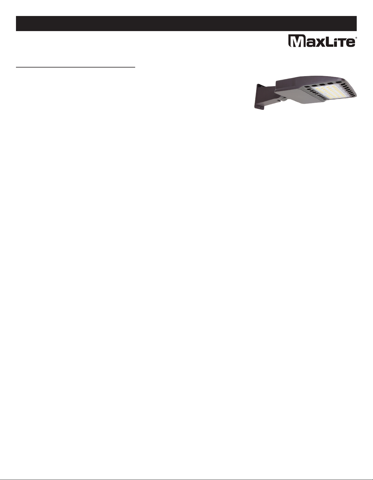
Modèles:
Série ARE
Caractéristiques de fonctionnement:
Température de fonctionnement: -40°C à 50°C
Plage de la tension d’entrée: 100-277Vca, 277-480Vca, 50/60Hz
1
®
L’image est pour des fins d’illustration
seulement. Votre modèle peut être
différent.
Consignes générales de sécurité
© Droits d’auteur 2021. MaxLite, nc. Tous droits réservés.
12 York Ave, West Caldwell, NJ 07006 Tél: 800-555-5629 Fax: 973-244-7333 Email: inf[email protected]
Page: 1
REV: 10/14/21

A: Montage sur bras flexible:
Ce luminaire peut être installé sur un poteau à profil carré ou rond en utilisant le RPA (adaptateur rond pour poteaux). Le bras
flexible peut être orienté de 0 à 78° vers le haut ou vers le bas par incréments de 30° (voir la FIG. 2).
1. Au cas où il n’y a pas de modèle de trous sur le poteau, percez des trous en conformité avec le modèle dans la FIG. 3.
2. Ouvrez la plaque de couverture latérale du bras de montage en desserrant les 4 vis M3. (voir la FIG. 4).
3. Attachez l’adaptateur rond pour poteaux au support de montage, le cas échéant. Utilisez le joint EVA et la plaque
filetée, le cas échéant, comme illustré dans la FIG. 5.
Vis M3
Plaque de
couverture
Silicone
Fig. 2 Fig. 3
Fig. 4
Adaptateur
rond pour poteau EVA
Adaptateur
rond pour poteau EVA Vis M3
Fig. 5
Schéma général de câblage
PRÉCA TION: Débranchez l’alimentation électrique au fusible ou au disjoncteur avant de connecter
le luminaire à la source d’alimentation.
Connexion des panneaux à la source d’alimentation CA: Toutes les unités seront connectées de manière
individuelle à la source d’alimentation CA. Noir = Phase, Blanc = Commun, Vert = Terre
Fig. 1
Mode d’emploi Série ARE
Éclairage de zone MaxLite ARE à haut rendement
1
®
© Droits d’auteur 2021. MaxLite, nc. Tous droits réservés.
12 York Ave, West Caldwell, NJ 07006 Tél: 800-555-5629 Fax: 973-244-7333 Email: inf[email protected]
Page: 2
REV: 10/14/21
Percez des trous fixes sur le poteau pour un support direct
Installation et fonctionnement

Page: 3
REV: 10/14/21
Installation et fonctionnement
A: Montage sur bras flexible: (Suite)
4. Fixez le support de montage au poteau avec 2 boulons M10×50 à tête hexagonale interne. (voir la FIG. 6) Câblez le
luminaire en utilisant des connecteurs imperméables homologués UL. Utilisez le schéma de câblage comme illustré.
(voir la FIG. 7).
5. Fixez la plaque de couverture latérale au bras de montage avec les 4 vis M3. (voir la FIG. 8)
6. Pour orienter le luminaire, desserrez le boulon central d’articulation M16x45 sur le bras, orientez de 0 à 90° en toute
direction.
7. Vérifiez l’installation pour confirmer si le luminaire est bien fixé.
Vis M10
Poteau carré
Plaque filetée
Vis M10
Poteau rond
Fig. 6
Noir
Vert
Blanc
Noir
Vert
Blanc
Fig. 7
Fig. 8
Poteaux carrés: Poteaux ronds:
Mode d’emploi Série ARE
Éclairage de zone MaxLite ARE à haut rendement
1
®
© Droits d’auteur 2021. MaxLite, nc. Tous droits réservés.
12 York Ave, West Caldwell, NJ 07006 Tél: 800-555-5629 Fax: 973-244-7333 Email: inf[email protected]

Installation et fonctionnement
B. Montage à raccord lisse:
Ce luminaire peut être installé de 0° à 90° en toute direction, orienté par incréments de 30° (voir la FIG. 2) et le raccord
lisse s’adapte aux tenons OD ou aux supports de 6,03cm (2 3/8") standard dans le domaine. Connectez les fils
d’alimentation correctement, réalisez le câblage (voir la FIG. 9) et posez les fils dans le poteau.
1. À la fin, insérez le raccord lisse sur le poteau (voir la FIG. 10)
2. Serrez les quatre boulons M8x20 sur le raccord lisse et fixez-le au poteau (voir la FIG. 11).
3. Pour orienter le luminaire, desserrez le boulon central d’articulation M16x45 sur le bras, orientez de 0 à 90°
en toute direction.
4. Vérifiez l’installation pour confirmer si le luminaire est bien fixé.
Fig. 9
Noir
Vert
Blanc
Poteau de 6,03cm
2,375” diamètre
Fig. 10
Vis M3
Fig. 11
Dessins techniques de montage
BRAS:
20,57cm (8,1”)
12,44cm (5,6”)
0
90
90
12,44cm (4,9”)
RACCORD LISSE:
6,03cm (2 3/8")
0
90
90
7,62cm (3”)
20,82cm (8,2”)
12,44cm (3”)
Mode d’emploi Série ARE
Éclairage de zone MaxLite ARE à haut rendement
1
®
© Droits d’auteur 2021. MaxLite, nc. Tous droits réservés.
12 York Ave, West Caldwell, NJ 07006 Tél: 800-555-5629 Fax: 973-244-7333 Email: inf[email protected]
Page: 4
REV: 10/14/21

MaxLite nc. garantit ses produits pour une période minimale de CINQ (5) ans à partir de la date de l’achat de
MaxLite ou son distributeur / revendeur autorisé (la « Période de Garantie »), comme suit: Si un Produit ne fonctionne
pas correctement pendant la Période de Garantie suite à des défauts de matériaux ou de fabrication, MaxLite va,
à sa discrétion, réparer ou remplacer le produit avec un modèle identique ou similaire.
Veuillez consulter le site web de Maxlite (sur http://maxlite.com/resources/warranties) pour la version complète des
termes et conditions de garantie.
Limitation de Responsabilité
LA GARANT E QU PRÉCÈDE EST EXCLUS VE ET REPRÉSENTE LE SEUL RECOURS POUR TOUTES LES
RÉCLAMAT ONS, QU'ELLES SO ENT CONTRACTUELLES, C V LES OU AUTREMENT DÉCOULANT DE LA
DÉFA LLANCE DU PRODU T ET REMPLACE TOUTES LES AUTRES GARANT ES, EXPRESSES OU MPL C TES,
Y COMPR S TOUTES LES GARANT ES DE COMMERC AL SAT ON OU L'ADÉQUAT ON À UN USAGE
PART CUL ER DONT LES GARANT ES SONT EXPRESSÉMENT DÉCL NÉES DANS LA MESURE PERM SE PAR
LA LO ET, EN TOUT CAS, SONT L M TÉES À LA PÉR ODE DE GARANT E SPÉC F ÉE C -DESSUS. LA
RESPONSAB L TÉ DE MAXL TE EST L M TÉE AUX TERMES DE LA GARANT E EXPRESSE DÉF N E DANS LES
PRÉSENTES. MAXL TE NE SERA EN AUCUN CAS RESPONSABLE DES DOMMAGES PART CUL ERS,
ACCESSO RES OU CONSÉCUT FS, Y COMPR S, SANS S'Y L M TER, LES DOMMAGES RÉSULTANT DE LA
PERTE D'UT L SAT ON, DES BÉNÉF CES, DES AFFA RES OU DE LA BONNE VOLONTÉ, DES FRA S DE MA N
D'OEUVRE, DES FRA S DE DÉMÉNAGEMENT OU D' NSTALLAT ON, DE LA D M NUT ON DU N VEAU DE
LUM ÈRE DE LA LAMPE, ET / OU LA DÉTÉR ORAT ON DES PERFORMANCES DE LA LAMPE, QUE MAXL TE
SO T AVERT OU NON DE CETTE POSS B L TÉ. EN AUCUN CAS LA RESPONSAB L TÉ DE MAXL TE POUR UN
PRODU T DÉFECTUEUX NE DÉPASSERA LE PR X D'ACHAT DE CE PRODU T. LES SERV CES DE GARANT E
FOURN S EN VERTU DE CES TERMES ET COND T ONS NE GARANT SSENT PAS LE FONCT ONNEMENT
N NTERROMPU DES PRODU TS; MAXL TE NE SERA PAS RESPONSABLE DES DOMMAGES CAUSÉS PAR
TOUT RETARD MPL QUANT LA RÉPARAT ON SOUS GARANT E.
Cette garantie limitée vous donne des droits légaux spécifiques et vous pouvez également avoir d'autres droits qui
peuvent varier d'un État à l'autre. Puisque certains États ou juridictions n'autorisent pas l'exclusion ou la limitation
de responsabilité pour les dommages indirects ou accessoires, cette limitation peut ne pas s'appliquer à vous.
Informations de garantie
Mode d’emploi Série ARE
Éclairage de zone MaxLite ARE à haut rendement
1
®
© Droits d’auteur 2021. MaxLite, nc. Tous droits réservés.
12 York Ave, West Caldwell, NJ 07006 Tél: 800-555-5629 Fax: 973-244-7333 Email: inf[email protected]
Page: 5
REV: 10/14/21
This manual suits for next models
12
Table of contents
Languages:
Other MaxLite Outdoor Light manuals

MaxLite
MaxLite SEC Series User manual

MaxLite
MaxLite DBL Series User manual

MaxLite
MaxLite BL-CLR Series User manual

MaxLite
MaxLite GuardMax SECS Series User manual

MaxLite
MaxLite AR Series User manual

MaxLite
MaxLite maxLED MLLWP40LED50DS 150 Series User manual

MaxLite
MaxLite GL Series User manual

MaxLite
MaxLite ML1E 2DAR Series User manual

MaxLite
MaxLite ML7L4USB30 Series User manual

MaxLite
MaxLite GL Series User manual