Helios AIR1-AAHA Series User manual

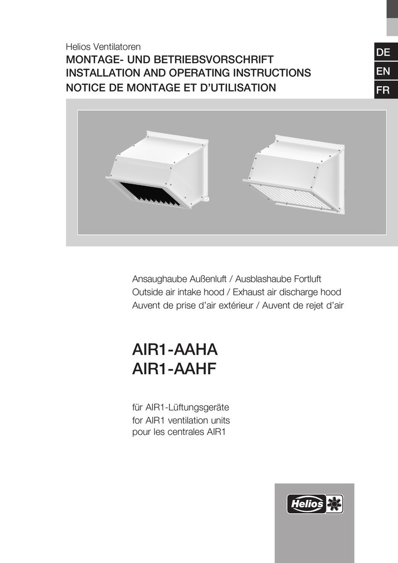
Ansaughaube Außenluft / Ausblashaube Fortluft
Outside air intake hood / Exhaust air discharge hood
Auvent de prise d’air extérieur / Auvent de rejet d’air
AIR1-AAHA
AIR1-AAHF
für AIR1-Lüftungsgeräte
for AIR1 ventilation units
pour les centrales AIR1
DE
EN
FR
Helios Ventilatoren
MONTAGE- UND BETRIEBSVORSCHRIFT
INSTALLATION AND OPERATING INSTRUCTIONS
NOTICE DE MONTAGE ET D’UTILISATION

DEDE
Ansaughaube Außenluft – AIR1-AAHA / Ausblashaube Fortluft – AIR1-AAHF
Montage- und Betriebsvorschrift
1
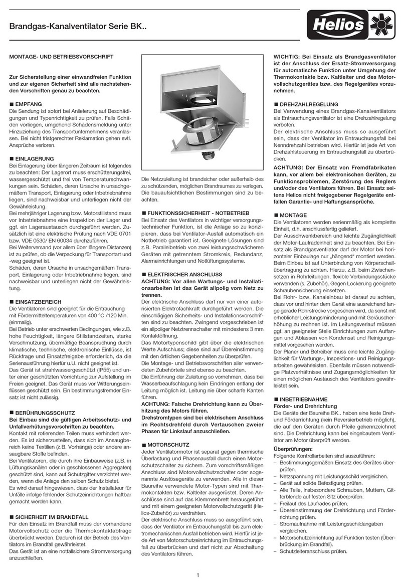
1.1 Wichtige Informationen
Zur Sicherstellung einer einwandfreien Funktion und zur eigenen Sicherheit sind alle nachstehenden Vorschriften genau
durchzulesen und zu beachten.
Dieses Dokument ist Teil des Produktes und als solches zugänglich und dauerhaft aufzubewahren. Der Betreiber ist
für die Einhaltung aller anlagenbezogenen Sicherheitsvorschriften verantwortlich.
1.2 Warnhinweise
Nebenstehende Symbole sind sicherheitstechnische Warnhinweise. Zur Vermeidung von Gefahrensituationen
müssen alle Sicherheitsvorschriften bzw. Symbole unbedingt beachtet werden!
m
GEFAHR
Warnung vor Gefahren, die bei Missachtung der Maßnahmen unmittelbar zu Tod oder schweren Verletzungen
führen.
m
WARNUNG
Warnung vor Gefahren, die bei Missachtung der Maßnahmen zu Tod oder schweren Verletzungen führen können.
mVORSICHT
Warnung vor Gefahren, die bei Missachtung der Maßnahmen zu Verletzungen führen können.
ACHTUNG
Warnung vor Gefahren, die bei Missachtung der Maßnahmen zu Sachschäden führen können.
1.3 Sicherheitshinweise
Für Einsatz und Betrieb gelten besondere Bestimmungen. Bei Zweifel ist Rückfrage erforder-
lich. Weitere Informationen sind den einschlägigen Normen und Gesetzestexten zu entnehmen.
m Bei allen Arbeiten am Gerät sind die allgemein gültigen Arbeitsschutz und
Unfallverhütungsvorschriften einzuhalten!
• Nicht unter der schwebenden Last aufhalten!
•Die Installation darf nur von geeignetem Fachpersonal durchgeführt werden!
• Gerät nur mit, für das Gewicht, geeigneten Transportmitteln bewegen. Beim Transport
Sicherheitsschuhe tragen!
• Beim Auspacken des Gerätes Handschuhe/Sicherheitsschuhe tragen.
• Geeignete Tragkraft und Trageigenschaften des Befestigungsuntergrunds sicherstellen und
diesbezüglich geeignete Befestigungsmittel verwenden.
• Alle anlagenbezogenen Sicherheitsvorschriften sind einzuhalten! Gegebenenfalls müssen
weitere länderspezifische Vorschriften eingehalten werden!
•Der Ausblasbereich muss frei von Gegenständen und Stoen sein, die weggeschleudert
werden können.
•Eine gleichmäßige Zuströmung und ein freier Ausblas sind zu gewährleisten!
1.4 Einsatzbereiche
Bestimmungsgemäßer Einsatz:
Die Ansaughaube Außenluft bzw. Ausblashaube Fortluft ist zur Installation an ein AIR1-Lüftungsgerät der Serie XH oder
RH, zur Verhinderung des Eindringens von Schmutzpartikeln oder ähnlichem, konzipiert. Die Ansaughaube Außenluft
hat einen Tropfenabscheider, um das Eindringen von Wasser in das Lüftungsgerät zu verhindern.
Die Ansaughaube Außenluft bzw. Ausblashaube Fortluft ist ausschließlich für AIR1-Lüftungsgeräte der Baureihe XH
oder RH von Helios Ventilatoren geeignet.
AIR1-AAHA AIR1-AAHF
Ansaughaube Außenluft Ausblashaube Fortluft
1.5 Personenqualifikation
Die Installation darf nur von Fachkräften (z.B. Industriemechaniker, Mechatroniker, Schlosser oder vergleichbar) durch-
geführt werden.
KAPITEL 1
SICHERHEIT
ACHTUNG
m
VORSICHT
m
WARNUNG
mm
GEFAHR

DEDE
Ansaughaube Außenluft – AIR1-AAHA / Ausblashaube Fortluft – AIR1-AAHF
Montage- und Betriebsvorschrift
2
2.1 Garantieansprüche – Haftungsausschluss
Alle Ausführungen dieser Dokumentation sowie der Montage- und Betriebsvorschrift des entsprechenden Lüftungsgeräts
müssen beachtet werden, sonst entfällt die Gewährleistung. Gleiches gilt für Haftungsansprüche an Helios Ventilatoren.
Der Gebrauch von Zubehörteilen die nicht von Helios empfohlen oder angeboten werden, ist nicht statthaft. Eventuell
auftretende Schäden unterliegen nicht der Gewährleistung. Veränderungen und Umbauten am Gerät sind nicht zuläs-
sig und führen zum Verlust der Konformität, jegliche Gewährleistung und Haftung ist in diesem Fall ausgeschlossen.
2.2 Transport
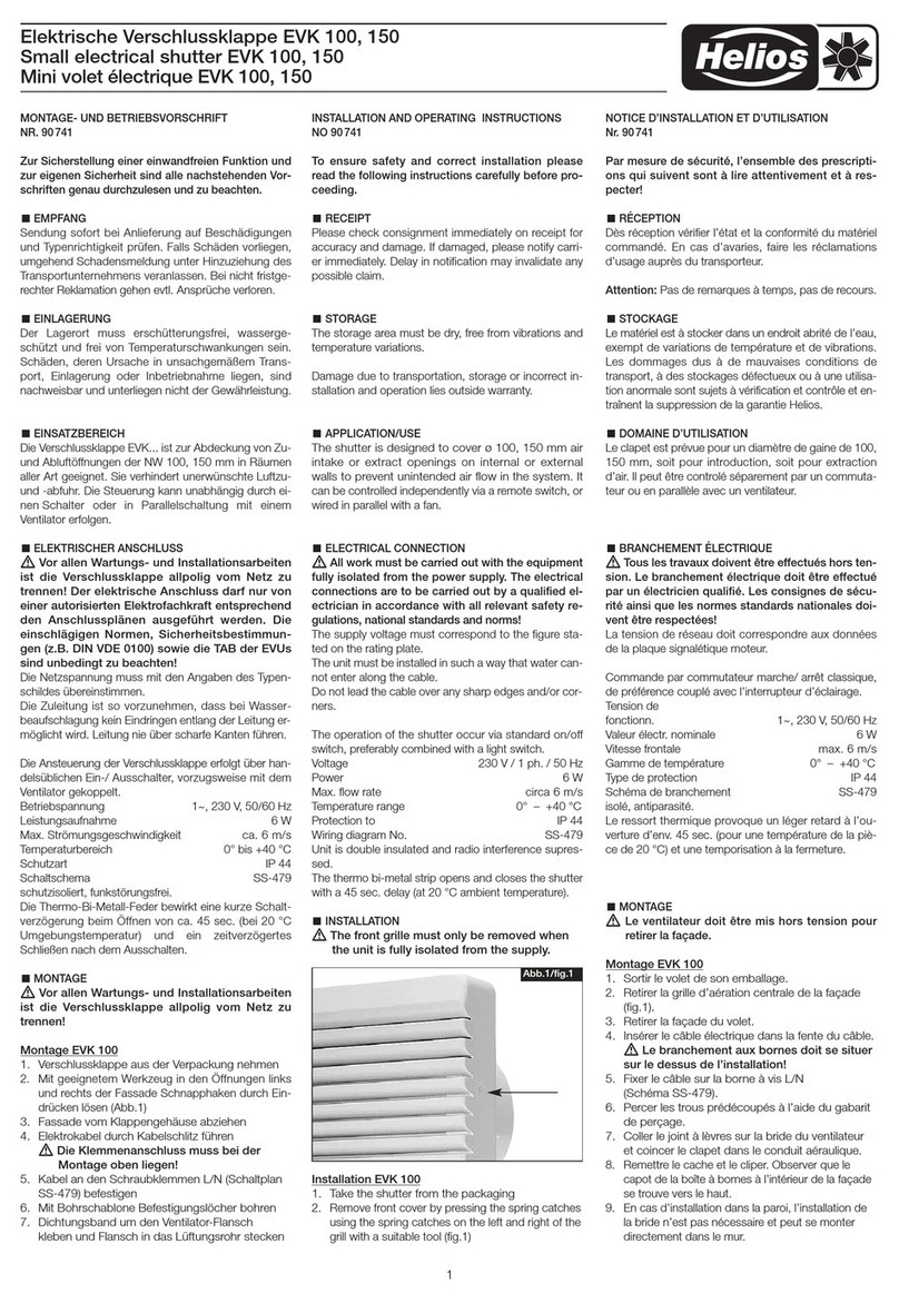
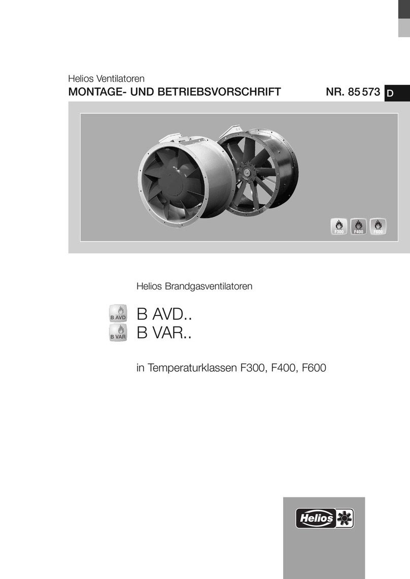
Die Ansaughaube Außenluft bzw. Ausblashaube Fortluft ist werkseitig so verpackt, dass sie gegen normale
Transportbelastungen geschützt ist. Der Transport ist sorgfältig durchzuführen. Es wird empfohlen das Gerät in der
Originalverpackung zu belassen.
2.3 Sendungsannahme
Die Sendung ist sofort bei Anlieferung auf Beschädigungen und Typenrichtigkeit zu prüfen. Falls Schäden vorliegen,
umgehend Schadensmeldung unter Hinzuziehung des Transportunternehmens veranlassen. Bei nicht fristgerechter
Reklamation gehen evtl. Ansprüche verloren.
3.1 Abmessungen
– Ansaughaube Außenluft AIR1-AAHA
KAPITEL 2
ALLGEMEINE HINWEISE
KAPITEL 3
MONTAGE
Type A B C D R S T U V W X
AIR1-AAHA XH 1000 375 270 332 162 343 238 315 210 – – –
AIR1-AAHA XH 1500/RH 1500 410 370 486 195 378 338 350 310 – – –
AIR1-AAHA XH 2500/RH 2000 530 370 486 195 498 338 470 310 – – –
AIR1-AAHA XH 3500-4500/RH 3000 640 470 525 200 608 438 580 410 – – –
AIR1-AAHA XH 5500/RH 5000-6000 915 530 525 200 883 438 855 410 498 – –
AIR1-AAHA XH 7000/RH 8000 1115 530 525 200 1083 438 1055 410 498 361,1 –
AIR1-AAHA XH 8500/RH 9500 1260 530 525 200 1228 438 1200 410 498 409,4 –
AIR1-AAHA RH 12000 1595 630 575 200 1503 538 1475 510 598 501,1 1563
AIR1-AAHA RH 15000 1720 830 675 200 1628 738 1600 710 798 814,2 1688
W
T
R
V
U
S
A
X
B
C
D
Art.-Nr.
Type
A
B
C
D
R
S
T
U
V
W
X
---
---
---
---
- -
-
-
Abb.1

DEDE
Ansaughaube Außenluft – AIR1-AAHA / Ausblashaube Fortluft – AIR1-AAHF
Montage- und Betriebsvorschrift
3
– Ausblashaube Fortluft AIR1-AAHF
3.2 Montage
Die Sicherheits- und Warnhinweise der Montage- und Betriebsvorschrift des AIR1-Lüftungsgeräts müssen unbe-
dingt beachtet werden!
m Gefahr von Personen- und Sachschäden!
Innenliegende Blechteile haben scharfe Kanten und Kerben, die bei der Installation und Wartung des Geräts
und/oder des Zubehörs zu Kratzern/Verletzungen führen können.
– Die Installation und Wartung des Geräts darf nur von qualifiziertem Fachpersonal durchgeführt werden.
– Geeignete Schutzausrüstung ist zu tragen.
Gefährdung durch bewegliche Teile (Gebläse) und heiße Oberflächen.
Wartung erst nach 3 Minuten Wartezeit durchführen!
Um einen Kurzschluß zu vermeiden und einen Abstand zwischen der Außen- und Fortlufthaube nach DIN 16798 zu
gewährleisten, ist eine Kanalverlängerung für die Außenluftansaugung oder Fortluftführung einzuplanen.
1. Dichtstreifen auf die Dichtoberfläche der Ansaug- bzw. Ausblashaube aufbringen, s. Abb.3.
W
T
R
V
U
S
A
X
B
C
Art.-Nr.
Type
A
B
C
R
S
T
U
V
W
X
---
---
---
---
- -
-
-
Abb.2
Type A B C R S T U V W X
AIR1-AAHF XH 1000 375 270 235 343 238 315 210 – – –
AIR1-AAHF XH 1500/RH 1500 410 370 338 378 338 350 310 – – –
AIR1-AAHF XH 2500/RH 2000 530 370 338 498 338 470 310 – – –
AIR1-AAHF XH 3500-4500/RH 3000 640 470 375 608 438 580 410 – – –
AIR1-AAHF XH 5500/RH 5000-6000 915 530 375 883 438 855 410 498 – –
AIR1-AAHF XH 7000/RH 8000 1115 530 375 1083 438 1055 410 498 361,1 –
AIR1-AAHF XH 8500/RH 9500 1260 530 375 1228 438 1200 410 498 409,4 –
AIR1-AAHA RH 12000 1595 630 415 1503 538 1475 510 598 501,1 1563
AIR1-AAHA RH 15000 1720 830 566 1628 738 1600 710 798 814,2 1688
nmlr
m
WARNUNG
m
WARNUNG
Abb.3

DEDE
Ansaughaube Außenluft – AIR1-AAHA / Ausblashaube Fortluft – AIR1-AAHF
Montage- und Betriebsvorschrift
4
2. Ansaug- bzw. Ausblashaube an den vier Ecken des Geräts sowie ggfs. vorhandenen Zwischenbohrungen, mit
Schrauben und Unterlegscheiben M8x16, montieren, s.Abb.4.
4.1 Instandhaltung und Wartung
Reinigungs- und Wartungsarbeiten dürfen nur von einer Elektrofachkraft durchgeführt werden.
m Lebensgefahr durch elektrischen Stromschlag!
Vor allen Wartungs- und Installationsarbeiten sowie vor Önen des Klemmenkastens ist das Gerät allpolig
vom Netz zu trennen!
Gefährdung durch elektrischen Schlag, bewegliche Teile (Ventilatoren) und ggf. heiße Oberflächen von optio-
nalen Nachheizregistern.
m Gefahr von Personen- und Sachschäden!
Innenliegende Blechteile haben scharfe Kanten und Kerben, die bei der Installation und Wartung des Geräts
und/oder des Zubehörs zu Kratzern/Verletzungen führen können.
– Die Installation und Wartung des Geräts darf nur von qualifiziertem Fachpersonal durchgeführt werden.
– Geeignete Schutzausrüstung ist zu tragen.
Es wird empfohlen die Ansaughaube Außenluft bzw. Ausblashaube Fortluft alle 6 Monate auf Schäden und Schmutz
zu überprüfen.
Abb.4
KAPITEL 4
INSTANDHALTUNG UND
WARTUNG
m
GEFAHR
nmlr
m
WARNUNG

ENEN
Outside air intake hood – AIR1-AAHA / Exhaust air discharge hood – AIR1-AAHF
Installation and Operating Instructions
1
1.1 Important information
In order to ensure complete and eective operation and for your own safety, all of the following instructions should be
read carefully and observed.
This document should be regarded as part of the product and as such should be kept accessible and durable. The
operator is responsible for complying with all plant-related safety regulations.
1.2 Warning instructions
The adjacent symbols are safety-relevant prominent warning symbols. All safety regulations and/or symbols
in this document must be absolutely adhered to, so that any risks of injury and dangerous situations are pre-
vented!
m DANGER
Indicates dangers which will directly result in death or serious injury if the safety instruction is not followed.
m WARNING
Indicates dangers which will result in death or serious injury if the safety instruction is not followed.
m CAUTION
Indicates dangers which can result in injuries if the safety instruction is not followed.
ATTENTION
Indicates dangers which can result in material damage if the safety instruction is not followed.
1.3 Safety instructions
Special regulations apply for use, connection and operation; consultation is required in case of
doubt. Further information can be found in the relevant standards and legal texts.
m With regard to all work, the generally applicable safety at work and accident prevention
regulations must be observed!
• Do not stand under suspended loads!
•The installation must only be carried out by suitable specialist personnel!
• Only transport fans using means of transport that are appropriate for the weight. Wear pro-
tective footwear during transport!
• Wear protective gloves/footwear when unpacking the unit.
• Ensure the suitable load capacity and properties of the mounting surface and use suitable
mounting material.
• All plant-related safety regulations must be observed! If applicable, further country-specific
regulations must also be observed!
•The outlet area must be kept free from objects and material that could be ejected.
•A uniform inflow and free outlet must be ensured!
1.4 Area of application
Intended use:
The outside air intake hood or exhaust air discharge hood is designed for installation on an AIR1 ventilation unit in
series XH or RH to prevent the freezing of dirt particles or the like. The outside air intake hood has a droplet separator
to prevent the ingress of water in the ventilation unit.
The outside air intake hood or exhaust air discharge hood is designed exclusively for AIR1 ventilation units in series XH
or RH from Helios Ventilatoren.
AIR1-AAHA AIR1-AAHF
Outside air intake hood Exhaust air discharge hood
1.5 Personnel qualification
The installation may only be carried out by specialists (e.g. industrial mechanics, mechatronics engineers, metal workers
or persons with comparable training).
CHAPTER 1
SAFETY
ATTENTION
m
CAUTION
m
WARNING
mm
DANGER

ENEN
Outside air intake hood – AIR1-AAHA / Exhaust air discharge hood – AIR1-AAHF
Installation and Operating Instructions
2
2.1 Warranty claims – Exclusion of liability
All versions of this documentation must be observed, otherwise the warranty shall cease to apply. The same applies
to liability claims against Helios Ventilatoren. The use of accessory parts, which are not recommended or oered by
Helios, is not permitted. Any possible damages are not covered by the warranty. Changes and modifications to the
unit are not permitted and lead to a loss of conformity, and any warranty and liability shall be excluded in this case.
2.2 Shipping
The outside air intake hood or exhaust air discharge hood is packed ex works in such a way that it is protected against
normal transport strain. Carry out the shipping carefully. It is recommended to leave the unit in the original packaging.
2.3 Receipt
The shipment must be checked for damage and correctness immediately upon delivery. If there is any damage,
promptly report the damage with the assistance of the transport company. If complaints are not made within the agreed
period, any claims could be lost.
3.1 Dimensions
– Outside air intake hood AIR1-AAHA
CHAPTER 2
GENERAL INFORMATION
CHAPTER 3
INSTALLATION
Type A B C D R S T U V W X
AIR1-AAHA XH 1000 375 270 332 162 343 238 315 210 – – –
AIR1-AAHA XH 1500/RH 1500 410 370 486 195 378 338 350 310 – – –
AIR1-AAHA XH 2500/RH 2000 530 370 486 195 498 338 470 310 – – –
AIR1-AAHA XH 3500-4500/RH 3000 640 470 525 200 608 438 580 410 – – –
AIR1-AAHA XH 5500/RH 5000-6000 915 530 525 200 883 438 855 410 498 – –
AIR1-AAHA XH 7000/RH 8000 1115 530 525 200 1083 438 1055 410 498 361,1 –
AIR1-AAHA XH 8500/RH 9500 1260 530 525 200 1228 438 1200 410 498 409,4 –
AIR1-AAHA RH 12000 1595 630 575 200 1503 538 1475 510 598 501,1 1563
AIR1-AAHA RH 15000 1720 830 675 200 1628 738 1600 710 798 814,2 1688
W
T
R
V
U
S
A
X
B
C
D
Art.-Nr.
Type
A
B
C
D
R
S
T
U
V
W
X
---
---
---
---
- -
-
-
Fig.1

ENEN
Outside air intake hood – AIR1-AAHA / Exhaust air discharge hood – AIR1-AAHF
Installation and Operating Instructions
3
– Exhaust air discharge hood AIR1-AAHF
3.2 Installation
The safety and warning instructions in the Installation and Operating Instructions for the AIR1 ventilation unit must
be observed in any case!
m Risk of personal injury and material damage!
Internal sheet metal parts have sharp edges and notches that can cause scratches/injuries during installation
and maintenance of the unit and/or accessories.
– The installation and maintenance of the unit may only be carried out by qualified specialist personnel.
– Suitable protective equipment must be worn.
Risk due to electric shock, moving parts (fan) and hot surfaces.
Only carry out maintenance after a waiting period of 3 minutes!
In order to avoid a short circuit and to ensure a distance between the outside and exhaust air hood in accordance with
EN 16798, a duct extension must be planned for the outside air intake or exhaust air duct.
1. Apply sealing strips to the sealing surface of the intake or discharge hood, see Fig.3.
W
T
R
V
U
S
A
X
B
C
Art.-Nr.
Type
A
B
C
R
S
T
U
V
W
X
---
---
---
---
- -
-
-
Fig.2
Type A B C R S T U V W X
AIR1-AAHF XH 1000 375 270 235 343 238 315 210 – – –
AIR1-AAHF XH 1500/RH 1500 410 370 338 378 338 350 310 – – –
AIR1-AAHF XH 2500/RH 2000 530 370 338 498 338 470 310 – – –
AIR1-AAHF XH 3500-4500/RH 3000 640 470 375 608 438 580 410 – – –
AIR1-AAHF XH 5500/RH 5000-6000 915 530 375 883 438 855 410 498 – –
AIR1-AAHF XH 7000/RH 8000 1115 530 375 1083 438 1055 410 498 361,1 –
AIR1-AAHF XH 8500/RH 9500 1260 530 375 1228 438 1200 410 498 409,4 –
AIR1-AAHA RH 12000 1595 630 415 1503 538 1475 510 598 501,1 1563
AIR1-AAHA RH 15000 1720 830 566 1628 738 1600 710 798 814,2 1688
nmlr
m
WARNING
m
WARNING
Fig.3

ENEN
Outside air intake hood – AIR1-AAHA / Exhaust air discharge hood – AIR1-AAHF
Installation and Operating Instructions
4
2. Mount the intake or discharge hood on the four corners of the unit and, if available, provisional holes, with
screws and washers M8x16, see Fig.4.
4.1 Servicing and maintenance
Cleaning and maintenance work may only be carried out by an electrician.
m Danger to life due to electric shock!
The AIR1 unit must be fully isolated from the mains power supply before all maintenance and installation work!
Danger of electric shock, moving parts (fans) and potentially hot surfaces of optional auxiliary heating regis-
ters.
m Risk of personal injury and material damage!
Internal sheet metal parts have sharp edges and notches that can cause scratches/injuries during installation
and maintenance of the unit and/or accessories.
– The installation and maintenance of the unit may only be carried out by qualified specialist personnel.
– Suitable protective equipment must be worn.
It is recommended to check the outside air intake hood or exhaust air discharge hood for damage and dirt every 6
months.
Fig.4
CHAPTER 4
SERVICING AND
MAINTENANCE
m
DANGER
nmlr
m
WARNING

FRFR
Auvent de prise d’air extérieur – AIR1-AAHA / Auvent de rejet d’air – AIR1-AAHF
Notice de montage et d’utilisation
1
1.1 Informations importantes
Il est important de bien lire et suivre l’ensemble des consignes suivantes pour le bon fonctionnement de l’appareil et
pour la sécurité des utilisateurs.
Ce document fait partie du produit et doit être conservé à portée de main comme référence. L’exploitant est tenu de
faire respecter toutes les règles de sécurité relatives à l’installation.
1.2 Précautions
Les symboles ci-contre indiquent une consigne de sécurité. Toutes les consignes de sécurité ainsi que les
symboles doivent être impérativement respectés afin d’éviter tout danger!
m
DANGER
Mise en garde contre des dangers qui, en cas de non-respect des mesures, entraînent immédiatement la mort ou de
graves blessures.
m
AVERTISSEMENT
Mise en garde contre des dangers qui, en cas de non-respect des mesures, peuvent entraîner la mort ou de graves
blessures.
mATTENTION
Mise en garde contre des dangers qui, en cas de non-respect des mesures, peuvent entraîner des blessures.
Point important
Mise en garde contre des dangers qui, en cas de non-respect des mesures, peuvent entraîner des dégâts matériels.
1.3 Consignes de sécurité
Le fonctionnement et l’utilisation relèvent de dispositions spécifiques; en cas de doute, nous
contacter. Des informations supplémentaires sont consultables dans les normes et textes de
loi.
m Lors de la manipulation de l’appareil, veiller à bien respecter les règles de sécurité
afin d’éviter tout accident!
• Ne pas rester sous une charge suspendue!
•L’installation doit exclusivement être eectuée par un personnel dûment qualifié!
• Pour déplacer l’appareil, toujours utiliser des moyens de transport prévus pour supporter
son poids. Lors du transport, porter des chaussures de sécurité!
• Porter des gants de protection et des chaussures de sécurité lors du déballage de l’appareil.
• Vérifier la capacité de charge et les caractéristiques du support de fixation afin d’utiliser les
moyens de fixation adéquats.
• Toutes les consignes d’installation doivent être respectées! Le cas échéant, les autres ré-
glementations nationales spécifiques doivent être respectées!
•La zone de rejet d’air doit être exempte d’objets et de substances susceptibles d’être pro-
jetés.
•Veiller à ce que l’amenée d’air soit uniforme et à ce que le rejet d’air soit libre!
1.4 Domaines d’utilisation
Utilisation conforme:
L’auvent de prise d’air extérieur et l’auvent de rejet d’air sont conçus pour être installés sur les centrales AIR1 XH ou RH
afin d’empêcher la pénétration de particules de saleté ou d’autres particules similaires. L’auvent de prise d’air extérieur
dispose d’un séparateur de gouttelettes qui empêche la pénétration d’eau dans la centrale.
L’auvent de prise d’air extérieur et l’auvent de rejet d’air sont uniquement compatibles avec les centrales AIR1 XH et
RH d’Helios Ventilateurs.
AIR1-AAHA AIR1-AAHF
Auvent de prise d’air extérieur Auvent de rejet d’air
1.5 Qualification du personnel
L’installation doit exclusivement être eectuée par du personnel qualifié (par ex., mécanicien industriel, mécatronicien,
mécanicien-ajusteur, etc.).
CHAPITRE 1
SÉCURITÉ
POINT IMPORTANT
m
ATTENTION
m AVERTISSEMENT
m m
DANGER

FRFR
Auvent de prise d’air extérieur – AIR1-AAHA / Auvent de rejet d’air – AIR1-AAHF
Notice de montage et d’utilisation
2
2.1 Demandes de garantie – Réserves du constructeur
Toutes les consignes énoncées dans le présent document et dans la notice de montage et d’utilisation de la centrale
AIR1 concernée doivent être respectées sous peine d’annulation de la garantie. Il en est de même pour toute impli-
cation de responsabilité d’Helios Ventilateurs. L’utilisation d’accessoires non conseillés ou proposés par Helios n’est
pas permise. Les dégâts causés par cette mauvaise utilisation ne sont pas couverts par la garantie. Les changements
et transformations de l’appareil sont interdits et entraînent une perte de conformité: la garantie et la responsabilité du
fabricant s’annulent.
2.2 Transport
L’auvent de prise d’air extérieur et l’auvent de rejet d’air sont emballés en usine de manière à être protégés des dégâts
de transport courants. Transporter l’appareil avec précautions. Il est préférable de laisser l’appareil dans son emballage
d’origine.
2.3 Réception de la marchandise
Dès réception, vérifier l’état et la conformité du matériel commandé. En cas de dégâts, les signaler immédiatement
en mentionnant le nom du transporteur. Attention, le non-respect de ces procédures peut entraîner le rejet de la ré-
clamation.
3.1 Dimensions
– Auvent de prise d’air extérieur AIR1-AAHA
CHAPITRE 2
INFORMATIONS
GÉNÉRALES
CHAPITRE 3
MONTAGE
W
T
R
V
U
S
A
X
B
C
D
Art.-Nr.
Type
A
B
C
D
R
S
T
U
V
W
X
---
---
---
---
- -
-
-
Fig.1
Type A B C D R S T U V W X
AIR1-AAHA XH 1000 375 270 332 162 343 238 315 210 – – –
AIR1-AAHA XH 1500/RH 1500 410 370 486 195 378 338 350 310 – – –
AIR1-AAHA XH 2500/RH 2000 530 370 486 195 498 338 470 310 – – –
AIR1-AAHA XH 3500-4500/RH 3000 640 470 525 200 608 438 580 410 – – –
AIR1-AAHA XH 5500/RH 5000-6000 915 530 525 200 883 438 855 410 498 – –
AIR1-AAHA XH 7000/RH 8000 1115 530 525 200 1083 438 1055 410 498 361,1 –
AIR1-AAHA XH 8500/RH 9500 1260 530 525 200 1228 438 1200 410 498 409,4 –
AIR1-AAHA RH 12000 1595 630 575 200 1503 538 1475 510 598 501,1 1563
AIR1-AAHA RH 15000 1720 830 675 200 1628 738 1600 710 798 814,2 1688

FRFR
Auvent de prise d’air extérieur – AIR1-AAHA / Auvent de rejet d’air – AIR1-AAHF
Notice de montage et d’utilisation
3
– Auvent de rejet d’air AIR1-AAHF
3.2 Montage
Les précautions et les consignes de sécurité figurant dans la notice de montage et d’utilisation de la centrale AIR1
doivent impérativement être respectés!
m Risque de dommages corporels et matériels!
Les pièces en tôle situées à l’intérieur présentent des arêtes coupantes et des encoches qui peuvent provo-
quer des rayures/blessures lors de l’installation et de l’entretien de l’appareil et/ou des accessoires.
– L’installation et la maintenance de l’appareil doivent exclusivement être eectués par un personnel qualifié.
– Porter un équipement de protection individuelle.
Danger lié aux pièces mobiles (ventilateur) et aux surfaces chaudes.
Attendre 3minutes avant d’eectuer la maintenance!
Afin d‘éviter un court-circuit et de garantir une distance entre les hottes d‘air extérieur et d‘air rejeté conformément à
la norme DIN 16798, une extension de conduit doit être prévue pour le conduit d‘air extérieur et d‘air rejeté.
1. Appliquer des bandes d’étanchéité sur la surface d’étanchéité de l’auvent de prise d’air extérieur et de l’auvent
de rejet d’air (voir Fig.3).
W
T
R
V
U
S
A
X
B
C
Art.-Nr.
Type
A
B
C
R
S
T
U
V
W
X
---
---
---
---
- -
-
-
Fig.2
Type A B C R S T U V W X
AIR1-AAHF XH 1000 375 270 235 343 238 315 210 – – –
AIR1-AAHF XH 1500/RH 1500 410 370 338 378 338 350 310 – – –
AIR1-AAHF XH 2500/RH 2000 530 370 338 498 338 470 310 – – –
AIR1-AAHF XH 3500-4500/RH 3000 640 470 375 608 438 580 410 – – –
AIR1-AAHF XH 5500/RH 5000-6000 915 530 375 883 438 855 410 498 – –
AIR1-AAHF XH 7000/RH 8000 1115 530 375 1083 438 1055 410 498 361,1 –
AIR1-AAHF XH 8500/RH 9500 1260 530 375 1228 438 1200 410 498 409,4 –
AIR1-AAHA RH 12000 1595 630 415 1503 538 1475 510 598 501,1 1563
AIR1-AAHA RH 15000 1720 830 566 1628 738 1600 710 798 814,2 1688
nmlr
m AVERTISSEMENT
m AVERTISSEMENT
Fig.3

FRFR
Auvent de prise d’air extérieur – AIR1-AAHA / Auvent de rejet d’air – AIR1-AAHF
Notice de montage et d’utilisation
4
2. Monter les auvents de prise d’air extérieur et de rejet d’air en plaçant des vis M8x16 et des rondelles aux quatre
coins et, le cas échéant, dans les trous intermédiaires (voir Fig.4).
4.1 Entretien et maintenance
Les travaux de nettoyage et de maintenance doivent être eectués exclusivement par un électricien qualifié.
m Danger de mort par choc électrique!
Mettre impérativement l’appareil hors tension avant tous travaux d’entretien, d’installation et avant l’ouverture
du coret électrique!
Risque de choc électrique, risque lié aux pièces mobiles (ventilateurs) et aux surfaces chaudes des batteries
de chaue, le cas échéant.
m Risque de dommages corporels et matériels!
Les pièces en tôle situées à l’intérieur présentent des arêtes coupantes et des encoches qui peuvent provo-
quer des rayures/blessures lors de l’installation et de l’entretien de l’appareil et/ou des accessoires.
– L’installation et la maintenance de l’appareil doivent exclusivement être eectués par un personnel qualifié.
– Porter un équipement de protection individuelle.
Il est recommandé de contrôler l’absence d’endommagement et de saletés au niveau des auvents de prise d’air exté-
rieur et de rejet d’air tous les 6mois.
Fig.4
CHAPITRE 4
MAINTENANCE ET
ENTRETIEN
m
DANGER
nmlr
m AVERTISSEMENT

Auvent de prise d’air extérieur – AIR1-AAHA / Auvent de rejet d’air – AIR1-AAHF
Notice de montage et d’utilisation
FR

Auvent de prise d’air extérieur – AIR1-AAHA / Auvent de rejet d’air – AIR1-AAHF
Notice de montage et d’utilisation
FR

Als Referenz am Gerät gribereit aufbewahren! Druckschrift-Nr.
Please keep this manual for reference with the unit! Print-No.
Conservez cette notice à proximité de l’appareil! N° Réf. 29 729-001/23-0375/V03/0519/1023
Service und Information
DHELIOS Ventilatoren GmbH + Co KG · Lupfenstraße 8 · 78056 VS-Schwenningen FHELIOS Ventilateurs · Le Carré des Aviateurs · 157 av. Charles Floquet · 93155 Le Blanc Mesnil Cedex
CH HELIOS Ventilatoren AG · Tannstrasse 4 · 8112 Otelfingen GB HELIOS Ventilation Systems Ltd. · 5 Crown Gate · Wyncolls Road · Severalls Industrial Park ·
AHELIOS Ventilatoren · Postfach 854 · Siemensstraße 15 · 6023 Innsbruck Colchester · Essex · CO4 9HZ
www.heliosventilatoren.de
Other manuals for AIR1-AAHA Series
1
This manual suits for next models
1
Table of contents
Languages:
Other Helios Ventilation Hood manuals
Popular Ventilation Hood manuals by other brands
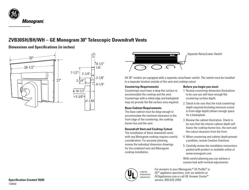
GE
GE ZVB30SH/BH/WH Dimensions and specifications
NEFF
NEFF D 96E2 N0 Operating and installation instructions
Grundig
Grundig GEDD 5481 XB User instructions
Greenheck
Greenheck Stainless Steel Round Backdraft Damper... Specification sheet

AEG
AEG X99384MV03 installation manual

Siemens
Siemens LC98KA570B instruction manual
