Helios BK Series User manual

Brandgas-Kanalventilator Serie BK..
1
MONTAGE- UND BETRIEBSVORSCHRIFT
Zur Sicherstellung einer einwandfreien Funktion
und zur eigenen Sicherheit sind alle nachstehen-
den Vorschriften genau zu beachten.
EMPFANG
Die Sendung ist sofort bei Anlieferung auf Beschädi-
gungen und Typenrichtigkeit zu prüfen. Falls Schä-
den vorliegen, umgehend Schadensmeldung unter
Hinzuziehung des Transportunternehmens veranlas-
sen. Bei nicht fristgerechter Reklamation gehen evtl.
Ansprüche verloren.
EINLAGERUNG
Bei Einlagerung über längeren Zeitraum ist folgendes
zu beachten: Der Lagerort muss erschütterungsfrei,
wassergeschützt und frei von Temperaturschwan-
kungen sein. Schäden, deren Ursache in unsachge-
mäßem Transport, Einlagerung oder Inbetriebnahme
liegen, sind nachweisbar und unterliegen nicht der
Gewährleistung.
Bei mehrjähriger Lagerung bzw. Motorstillstand muss
vor Inbetriebnahme eine Inspektion der Lager und
ggf. ein Lageraustausch durchgeführt werden. Zu-
sätzlich ist eine elektrische Prüfung nach VDE 0701
bzw. VDE 0530/ EN 60034 durchzuführen.
Bei Weiterversand (vor allem über längere Distanzen)
ist zu prüfen, ob die Verpackung für Transportart und
-weg geeignet ist.
Schäden, deren Ursache in unsachgemäßem Trans-
port, Einlagerung oder Inbetriebnahme liegen, sind
nachweisbar und unterliegen nicht der Gewährleis-
tung.
EINSATZBEREICH
Die Ventilatoren sind geeignet für die Entrauchung
mit Fördermitteltemperaturen von 400 °C /120 Min.
(einmalig).
Bei Betrieb unter erschwerten Bedingungen, wie z.B.
hohe Feuchtigkeit, längere Stillstandzeiten, starke
Verschmutzung, übermäßige Beanspruchung durch
klimatische, technische, elektronische Einflüsse, ist
Rückfrage und Einsatzfreigabe erforderlich, da die
Serienausführung hierfür u.U. nicht geeignet ist.
Das Gerät ist strahlwassergeschützt (IP55) und un-
ter einer geschützten Vorrichtung zur Aufstellung im
Freien geeignet. Das Gerät muss vor Witterungsein-
flüssen geschützt sein. Ein bestimmungsfremder Ein-
satz ist nicht zulässig.
BERÜHRUNGSSCHUTZ
Bei Einbau sind die gültigen Arbeitsschutz- und
Unfallverhütungsvorschriften zu beachten.
Kontakt mit rotierenden Teilen muss verhindert wer-
den. Es ist sicherzustellen, dass sich im Ansaugbe-
reich keine Textilien (z.B. Vorhänge) oder andere an-
saugbare Stoffe befinden.
Bei Ventilatoren, die durch ihre Einbauweise (z.B. in
Lüftungskanälen oder in geschlossenen Aggregaten)
geschützt sind, kann auf Schutzgitter verzichtet wer-
den, wenn die Anlage den selben Schutz bietet.
Es wird darauf hingewiesen, dass der Installateur für
Unfälle infolge fehlender Schutzeinrichtungen haftbar
gemacht werden kann.
SICHERHEIT IM BRANDFALL
Für den Einsatz im Brandfall muss der vorhandene
Motorvollschutz oder die Thermokontaktabfrage
überbrückt werden. Dadurch ist der Betrieb des Ven-
tilators im Brandfall gewährleistet.
Das Gerät ist an eine notfallsichere Stromversorgung
anzuschließen.
Die Netzzuleitung ist brandsicher oder außerhalb des
zu schützenden, möglichen Brandraumes zu verlegen.
Die bauaufsichtlichen Bestimmungen sind zu be-
achten.
FUNKTIONSSICHERHEIT - NOTBETRIEB
Bei Einsatz des Ventilators in wichtiger versorgungs-
technischer Funktion, ist die Anlage so zu konzi-
pieren, dass bei Ventilator-Ausfall automatisch ein
Notbetrieb garantiert ist. Geeignete Lösungen sind
z.B. Parallelbetrieb von zwei leistungsschwächeren
Geräten mit getrenntem Stromkreis, Redundanz,
Alarmeinrichtungen und Notlüftungssysteme.
ELEKTRISCHER ANSCHLUSS
ACHTUNG: Vor allen Wartungs- und Installati-
onsarbeiten ist das Gerät allpolig vom Netz zu
trennen.
Der elektrische Anschluss darf nur von einer auto-
risierten Elektrofachkraft durchgeführt werden. Die
einschlägigen Sicherheits- und Installationsvorschrif-
ten sind zu beachten. Zwingend vorgeschrieben ist
ein allpoliger Netztrennschalter mit mindestens 3 mm
Kontaktöffnung.
Das Motortypenschild gibt über die elektrischen
Werte Aufschluss; diese sind auf Übereinstimmung
mit den örtlichen Gegebenheiten zu überprüfen.
Die Montage- und Betriebsvorschriften aller verwen-
deten Zubehörteile sind ebenso zu beachten.
Die Einführung der Zuleitung so vornehmen, dass bei
Wasserbeaufschlagung kein Eindringen entlang der
Leitung möglich ist. Leitung nie über scharfe Kanten
führen.
ACHTUNG: Falsche Drehrichtung kann zu Über-
hitzung des Motors führen.
Drehstromtypen sind bei elektrischem Anschluss
im Rechtsdrehfeld durch Vertauschen zweier
Phasen für Linkslauf anzuschließen.
MOTORSCHUTZ
Jeder Ventilatormotor ist separat gegen thermische
Überlastung und Phasenausfall durch einen Motor-
schutzschalter zu sichern. Zum vorschriftsmäßigen
Anschluss sind Motorvollschutzschalter oder soge-
nannte Auslösegeräte zu verwenden. Alle in dieser
Baureihe verwendete Motor-Typen sind mit Ther-
mokontakten bzw. Kaltleiter ausgerüstet. Deren An-
schlüsse sind auf das Klemmenbrett herausgeführt
und mit einem geeigneten Motorvollschutzgerät (He-
lios-Zubehör) zu verdrahten.
Der elektrische Anschluss muss so ausgeführt sein,
dass der Ventilator im Entrauchungsfall bis zum elek-
tromechanischen Ausfall betrieben wird. Hierfür ist je-
de Art von Motorschutzeinrichtung im Entrauchungs-
fall zu überbrücken und darf nicht zur Abschaltung
des Ventilators führen.
WICHTIG: Bei Einsatz als Brandgasventilator
ist der Anschluss der Ersatz-Stromversorgung
für automatische Funktion unter Umgehung der
Thermokontakte bzw. Kaltleiter und des Motor-
vollschutzgerätes bzw. des Regelgerätes vorzu-
nehmen.
DREHZAHLREGELUNG
Bei Verwendung eines Brandgas-Kanalventilators
als Entrauchungsventilator ist eine Drehzahlregelung
verboten.
Der elektrische Anschluss muss so ausgeführt
sein, dass der Ventilator im Entrauchungsfall bei
Nenndrehzahl betrieben wird. Hierfür ist jede Art von
Drehzahlsteuerung im Entrauchungsfall zu überbrü-
cken.
ACHTUNG: Der Einsatz von Fremdfabrikaten
kann, vor allem bei elektronischen Geräten, zu
Funktionsproblemen, Zerstörung des Reglers
und/oder des Ventilators führen. Bei Einsatz sei-
tens Helios nicht freigegebener Regelgeräte ent-
fallen Garantie- und Haftungsansprüche.
MONTAGE
Die Ventilatoren werden serienmäßig als komplette
Einheit, d.h. anschlussfertig geliefert.
Der Ausschwenkbereich und leichte Zugänglichkeit
der Motor-Laufradeinheit sind zu beachten. Bei Ein-
satz als Brandgasventilator darf der Motor bei hori-
zontaler Einbaulage nur „hängend“ montiert werden.
Beim Einbau ist auf Unterbindung von Körperschall-
übertragung zu achten. Hierzu, z.B. beim Zwischen-
setzen in Rohrleitungen, flexible Verbindungsstücke
verwenden (s. Zubehör). Gegen Lockerung geeignete
Schraubensicherung einsetzen.
Bei Rohr- bzw. Kanaleinbau ist darauf zu achten,
dass vor und hinter dem Gerät eine ausreichend lan-
ge gerade Rohrstrecke vorgesehen wird, da sonst mit
erheblicher Leistungsminderung und mit Geräuscher-
höhung zu rechnen ist. Im Leitungsverlauf müssen
ggf. an geeigneter Stelle Einrichtungen zum Auffan-
gen und Ablassen von Kondensat und Reinigungs-
mittel vorgesehen werden.
Der Planer und Betreiber muss eine leichte Zugäng-
lichkeit für Wartungs-, Inspektions- und Reinigungs-
arbeiten gewährleisten. Ebenfalls müssen notwendi-
ge Platzverhältnisse und Zugangsmöglichkeiten für
einen möglichen Austausch des Ventilators gewähr-
leistet sein.
INBETRIEBNAHME
Förder- und Drehrichtung
Die Geräte der Baureihe BK.. haben eine feste Dreh-
und Förderrichtung (kein Reversierbetrieb möglich),
die auf den Geräten durch Pfeile gekennzeichnet
sind. Die Drehrichtung kann bei eingebautem Venti-
lator am Motor überprüft werden.
Überprüfungen:
Folgende Kontrollarbeiten sind auszuführen:
– Bestimmungsgemäßen Einsatz des Gerätes über-
prüfen.
– Netzspannung mit Leistungsschild vergleichen.
– Gerät auf solide Befestigung prüfen.
– Alle Teile, insbesondere Schrauben, Muttern, Git-
terblende auf festen Sitz überprüfen.
– Freilauf des Laufrades prüfen.
– Übereinstimmung der Drehrichtung und Förder-
richtung prüfen.
– Stromaufnahme mit Leistungsschildangaben
vergleichen.
– Motorschutzeinrichtung auf Funktion testen (Über-
brückung im Brandfall).
– Schutzleiteranschluss prüfen.

2
Brandgas-Kanalventilator Serie BK..
–
Abdichtung des Anschlusskabels und festen
Klemmsitz der Adern prüfen.
– Inbetriebnahme darf nur erfolgen, wenn der Be-
rührungsschutz des Laufrades sichergestellt ist.
HINWEISE / STÖRUNGSURSACHEN
–
Auslösung des thermischen Überlastungsschutzes
deutet auf Verschmutzung, Schwergängigkeit des
Laufrades und/oder der Lager hin. Eine zu hohe
Wicklungstemperatur durch zu geringe Motorküh-
lung, zu hohe Fördermittel- oder Umgebungstem-
peratur kann ebenfalls die Ursache sein.
– Anormale Geräusche können die Folge von aus-
gelaufenen Lagern sein.
– Vibrationen und Schwingungen können ihre Ur-
sache in einem unwuchtigen u.U. mit Schmutz be-
aufschlagten Laufrad oder in der Einbausituation
haben.
WARTUNG
ACHTUNG: Vor allen Wartungs- und Installati-
onsarbeiten ist das Gerät allpolig vom Netz zu
trennen.
Übermäßige Ablagerungen von Schmutz, Staub,
Fetten usw. auf Laufrad, Motor, Gitterblende und
v.a. zwischen Gehäuse und Laufrad sind unzulässig
und durch periodische Reinigung zu unterbinden. Die
Motor-Laufradeinheit ist zur Revision und Reinigung
ausschwenkbar. Alle Teile sind frei zugänglich.
Sofern das Gerät eine versorgungstechnisch wichti-
ge Funktion übernimmt, ist eine Wartung in halbjäh-
rigen Abstand, im Falle längeren Stillstands bei Wie-
derinbetriebnahme, durchzuführen.
Geräte, die nicht regelmäßig in Betrieb sind oder nur
für den Brandgaseinsatz vorgesehen sind, müssen
mindestens alle 3 Monate für mindestens eine Stun-
de betrieben werden.
REPARATUR
Defekte Brandgas-Ventilatoren sind komlpett zu tau-
schen. Eigene Reparaturversuche sind in keinem Fall
zulässig.
Der defekte Brandgas-Ventilator ist komplett in das
Werk der Firma Helios Ventilatoren zurück zu senden!
Helios Kundendienst kontkatieren.
Das Gerät muss nach erfolgtem Entrauchungsbe-
trieb entsorgt werden!
GERÄUSCHPEGEL
Die im Katalog genannten Geräuschwerte können
im Einbaufall erheblich abweichen, da der Schall-
druckpegel vom Absorptionsvermögen des Raumes,
der Einbausituation u.a. Faktoren abhängig ist. Ge-
räuschminderungen können durch den Einsatz von
Schalldämpfern (zu bestimmten Typen als Zubehör
lieferbar) erzielt werden.
STÖRUNGEN
Auslösen des Thermokontaktes/Motorschutzgerätes
kann verursacht werden durch:
– Starke Verschmutzung, Schwergängigkeit des
Laufrades und/oder der Kugellager,
– zu hohe Fördermitteltemperatur,
– zu geringen Druckverlust im Kanalnetz.
Anormale Geräusche können Ihre Ursache in
– falscher Drehrichtung,
– ausgelaufenen Kugellagern haben.
Vibrationen und Schwingungen können verursacht
werden durch:
–
ein unwuchtiges, u.U. mit Schmutz beaufschlag-
tem, Laufrad oder die Einbausituation.
Stark geminderte Leistung kann auftreten, wenn:
– die sich einstellenden Rohrleitungs- und Bauteil-
widerstände (Gitter, Klappen, Filter usw.) höher als
geplant liegen.
ZUBEHÖR, SCHALT- UND STEUERELEMENTE
Der Gebrauch von Zubehörteilen, die nicht von Helios
empfohlen oder angeboten werden, ist nicht statt-
haft. Eventuell auftretende Schäden unterliegen nicht
der Gewährleistung.
GARANTIE
Wenn die vorausgehenden Ausführungen nicht be-
achtet werden, entfällt unsere Gewährleistung und
Behandlung auf Kulanz. Gleiches gilt für abgeleitete
Haftungsansprüche an den Hersteller.
ZERTIFIZIERUNG
Diese Geräteserie ist nach DIN EN 12101-3 geprüft.
VORSCHRIFTEN / RICHTLINIEN
Bei ordnungsgemäßer Installation und bestimmungs-
gemäßem Betrieb entspricht das Gerät den zum Zeit-
punkt seiner Herstellung gültigen Vorschriften und
CE-Richtlinien.
3
Brandgas-Kanalventilator Serie BK..
M 3~
PTC
MSA, PTC Überwachung
Electronics for PTC monitoring
Électronique pour PTC surveillance
RHS 6+2
Revisions Hauptschalter
Revision main switches
Révision interrupteur principal
Versorgung Brandfall
Supply for emergency operation
Alimentation de secours
Versorgung, normaler Lüftungsbetrieb
Supply, normal operation
Alimentation, fonctionn. ventilation normale
RHS 6+2*
Revisions
Hauptschalter
K1
K1S1
S0
L1
N
S2
K2
K10
K10
K10
K11T
K2
K2
K1
K11T K2
1sec
Schaltungsvorschlag
Operation recommendation / Consigne de branchement
Prinzip-Steuerung
Principle layout
Principe contrôle
Steuerkontakt
Brandfall-Alarm
Control port contact emergency
Contact de contrôle alarme incendie
Normal-Betrieb
Normal operation
Fonctionn. normal
Ein
On
Marche
Brandfall
Emergency
operation
Cas d' incendie
Alarm
Alarm
Alarme
K1 K2
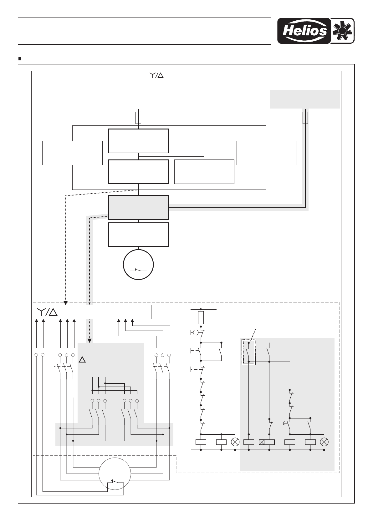
3~ mit bzw. ohne ThermoschutzBrandgas Ventilatoren
Smoke extract fan / Ventilateurs de désenfumage
DS 2, Aus/Y/D
Manual switch off/Y/
Commutateur manuel arrêt/ Y/
D
D
DS 2 FU
0-100% 100%
PTC
MSA
MD max. 25 A
MD, Motorvollschutzschalter
Motor protection unit
Protection moteur avec TK
FU Frequenzumrichter
Frequency inverters
Variateur de fréquence
85266 001 SS-1023 25.04.12
*mit FU, SS-924 beachten
with FU, follow SS-924
suivre SS-924 avec FU
MSA, MD,
F1,
F1, Motorschutzschalter
motor protection switch
disjoncteur moteur
F1
MD, F1
Schaltschema SS-1023

4
92614 002 SS-565 25.07.05
K1
K4K3
K2
U1
V1
W1 V2
U2
W2
M 3 ~
mit TK
K2K1
K2S1
S0
L1
N
S2
K3
K4
L1
L1
TK TK U1 V1 W1
L2
L2
L3
L3
L3 L2 L1
V2 U2 W2
MD
(TK)
K10
K10
K10
K11T
K4
K3 K4
K1
K2
K11T K4
1sec
-Betrieb, hohe Drehzahl
high speed /
Fonctionn. pleine vitesse
Brandfall !
Emergency operation / Cas d' incendie
MD / SS-518
Motorvollschutz
mit TK
M 4 / SS-144
Motorvollschutz
Y/ mit TKD DS 2 / SS-87
Aus/Stern/Dreieck
Drehzahlumschalter
Leistungsteil
Schützsteuerung
Y/D
RDS / SS-139
Trafo-Drehzahlst.
mit Motorvollsch. TK
Leistungsteil
Brandfall
RHS 6+2 / SS-505
Revisions
Hauptschalter
M 3 ~
mit TK
Versorgung, normaler Lüftungsbetrieb
Supply, normal operation
Alimentation, fonctionn. ventilation normale
Versorgung Brandfall
Supply for emergency operation
Alimentation de secours
MD
Motor protection unit
Protection moteur avec TK
M 4 Y/
Motor protection with Y/switch
Protection moteur avec Y/ comm.
D
D
D
RDS
Transfomer speed controller
with Motor protection
Transformateur régulateur de
vitesse avec protection moteur TK
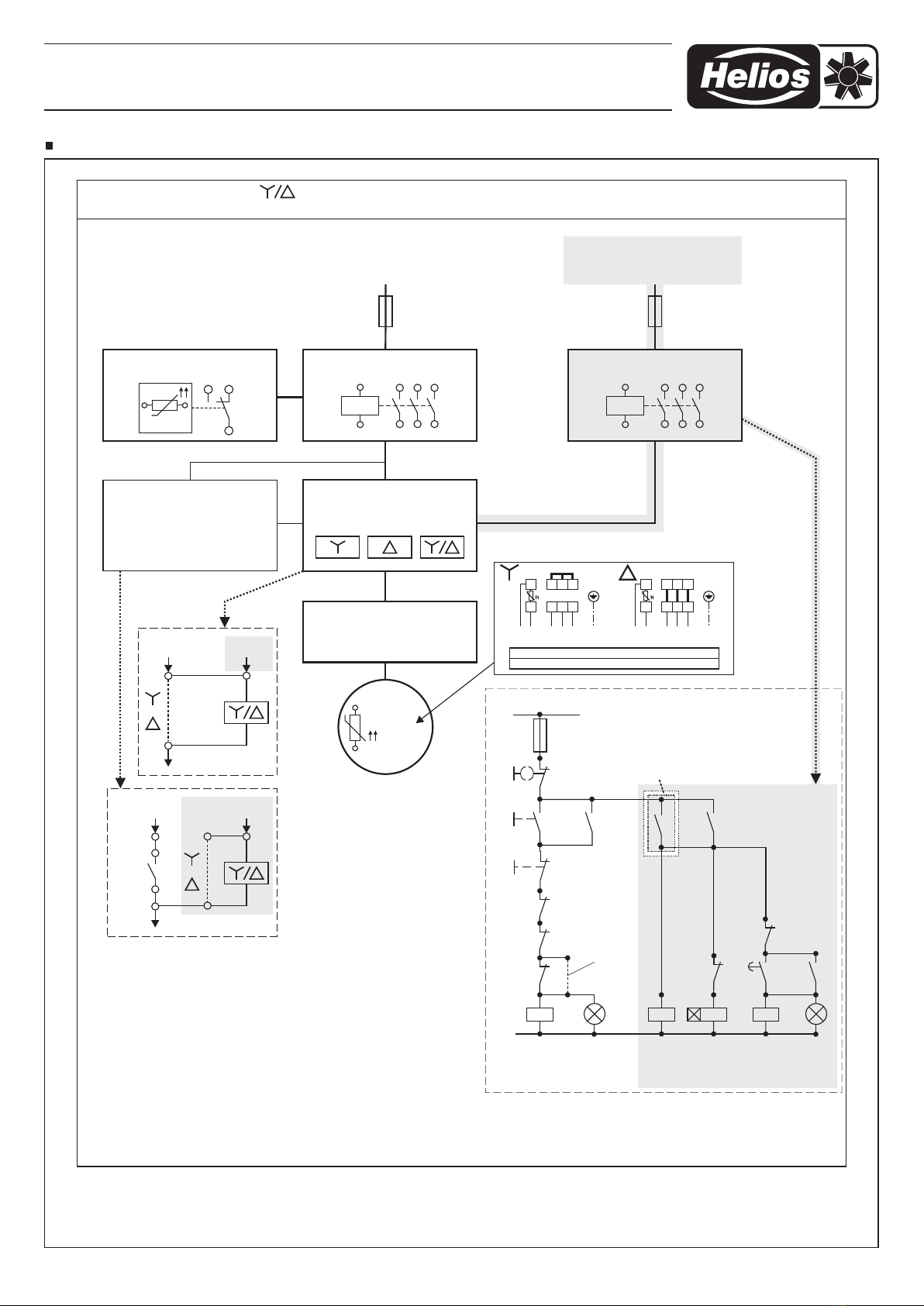
DS 2 Aus/Y/
Manual switch off/Y/
Commutateur manuel arrêt/ Y/
D
D
DLeistungsteil Schützst. Y/
Power unit, contactor control Y/
Circuit de puissance, contrôle
circuit contacteur Y/
D
D
D
Leistungsteil Brandfall
Power unit for emergency operation
Circuit de puissance en cas
d' incendie
RHS 6+2
Main switch
Interrupteur principal
Leistungsteil Brandfall, Schaltungsvorschlag / Power unit for emergency operation,
recommendation / Circuit de puissance en cas d' incendie, consigne de branchement
Prinzip-Steuerung
Principle layout
Principe contrôle
Steuerkontakt
Brandfall-Alarm
Control port contact emergency
Contact de contrôle alarme incendie
Normal-Betrieb
Normal operation
Fonctionn. normal
Ein
On
Marche
Brandfall
Emergency
operation
Cas d' incendie
Alarm
Alarm
Alarme
Normal - Betrieb Operation / Fonctionn.
Brandgas Ventilatoren
moke extract fan / Ventilateurs de désenfumage
Zweitourige 3~ mit TK
Two speed s à deux vitesses
Schaltschema SS-565, Motor für BK, 3 ~ AC mit Thermokontakt, BKD Prinzipanschluss
Brandgas-Kanalventilator Serie BK..

5
M
3~
PTC
PTC
MSA / SS-325.1
MSA
PTC Überwachung
Electronics for PTC monitoring
Électronique pour PTC surveillance Schützsteuerung
Circuit for motor control
Circuit pour moteur contrôle
RHS 6+2
Revisions Hauptschalter
Revision main switches
Révision interrupteur principal
Versorgung Brandfall
Supply for emergency operation
Alimentation de secours
Versorgung, normaler Lüftungsbetrieb
Supply, normal operation
Alimentation, fonctionn. ventilation normale
DS 2 / SS-87
Aus/Stern/Dreieck
Schalter manuell
Leistungsteil
Schützsteuerung
RHS 6+2 / SS-505
Revisions
Hauptschalter
K1
K1S1
S0
L1
N
S2
K2
MSA
K10
K10
K10
K11T
K2
K2
K1
K11T K2
1sec
Schaltungsvorschlag
Operation recommendation / Consigne de branchement
Prinzip-Steuerung
Principle layout
Principe contrôle
Steuerkontakt
Brandfall-Alarm
Control port contact emergency
Contact de contrôle alarme incendie
Normal-Betrieb
Normal operation
Fonctionn. normal
Ein
On
Marche
Brandfall
Emergency
operation
Cas d' incendie
Alarm
Alarm
Alarme
K1
K2
Bei Motor ohne PTC,
Brücke anstatt MSA-Öffner
notwendig!
Brandgas VentilatorenEintourige 3~ mit PTC bzw. ohne Thermoschutz
S with PTC avec PTCmoke extract fan / Ventilateurs de désenfumage
DS 2
Aus/Y/D
Manual switch off/Y/
Commutateur manuel arrêt/ Y/
D
D
Brandfall
Emergency operation
Cas d' incendie
92855 001 SS-776
W2 U2 V2KL
U1 V1 W1KL
KLKL L1 L2 L3 PE
W2 U2 V2KL
U1 V1 W1KL
KLKL L1 L2 L3 PE
Kaltleiter/
Thermistor
PTC PTC
Kaltleiter/
Thermistor
400 V 230 V/
690 V 400 V/
K1 K2
DS 2
K1 K2
Normal-Betrieb
92909 002 SS-565.1 04.02.10
Brandfall-Betrieb
Schaltschema SS-565.1, Motor für BK, 3 ~ AC mit PTC, BKD Prinzipanschluss
Brandgas-Kanalventilator Serie BK..
6
K1 K2
U1
U2
K1
K1S1
S0
L1
N
S2
K2
K2
K2
MW-H
(TK)
L1TK TK L1 N N
85499 033 SS-1269 12.02.18
1~ 1~
1~
Brandgas Ventilatoren, Thermokontakt separat / Smoke extract fan, thermal contact separate /
Ventilateurs de désenfumage, thermocontact sèparè
MD / SS-518
Motorvollschutz
mit TK
MW-H
Motor protection unit
Protection moteur avec TK
MWS
Transfomer speed controller
with Motor protection unit
Transformateur régulateur de
vitesse avec protection
moteur TK
Manueller Schalter Ein/Aus
Manual switch on/off
Commutateur manuel
marche/arrêt
Schützst. Ein/Aus
Power unit, contactor on/off
Circuit de puissance, contrôle
circuit contacteur marche/arrêt
RHS 3/1
Main switch
Interrupteur principal
MWS / SS-440
Trafo-Drehzahlst.
mit Motorvollsch. TK Manueller
Schalter
Ein / Aus
Schützsteuerung
Ein / Aus
RHS 3+1, Revisions
Hauptschalter
M 1 ~
mit TK
Schaltungsvorschlag / Recommendation / Consigne de branchement
Normal - Betrieb
Operation/Fonctionn.
Brandfall / Emergency
operation /
Cas d' incendie
M 1 ~
mit TK
Prinzip-Steuerung
Principle layout
Principe contrôle
Normal-Betrieb
Normal operation
Fonctionn. normal
Ein
On
Marche
Brandfall
Emergency
operation
Cas d' incendie
Alarm
Alarm
Alarme
Steuerkontakt
Brandfall-Alarm
Control port contact emergency
Contact de contrôle alarme incendie
Versorgung Brandfall
Supply for emergency operation
Alimentation de secours
Versorgung, normaler Lüftungsbetrieb
Supply, normal operation
Alimentation, fonctionn. ventilation normale
K1
K2
Anschlussbeispiel
connection examples
exemples de branchement
SS-1272
Beispiel
example
exemple
SS-1268
Schaltschema SS-1269, Motor für BK, 1~ mit Thermokontakt, BKW Prinzipanschluss
Brandgas-Kanalventilator Serie BK..
7
Schaltschema SS-1268, Klemmenkasten für BKW mit Thermokontakt in separat
85499 032 SS-1268 12.02.18
TB TB NL PE
U1
Z1TK
TK
Z2
C
C
U2
(TK) (TK)
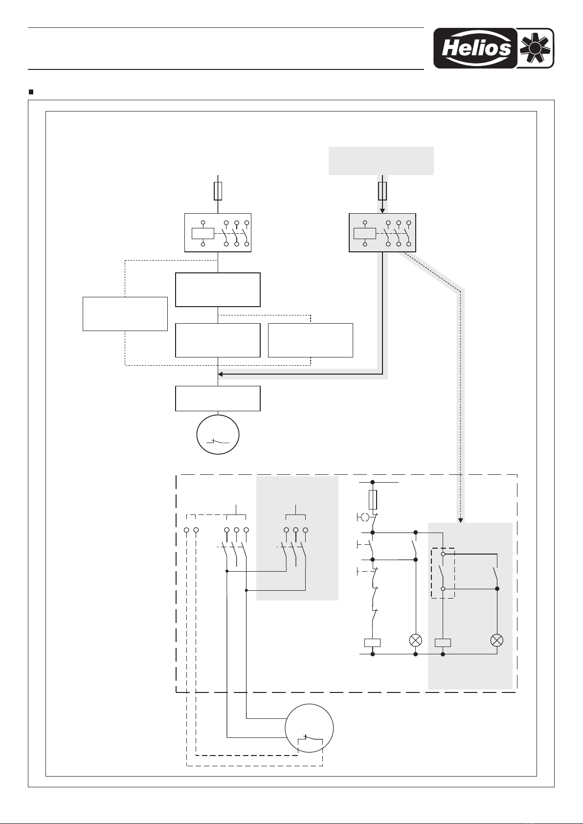
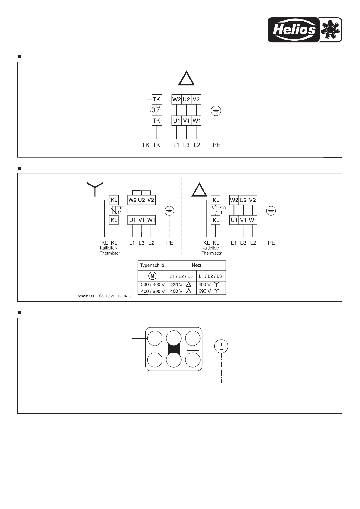
Schaltschema SS-1234, Klemmenkasten für BKD, 3 ~ AC mit Thermokontakt
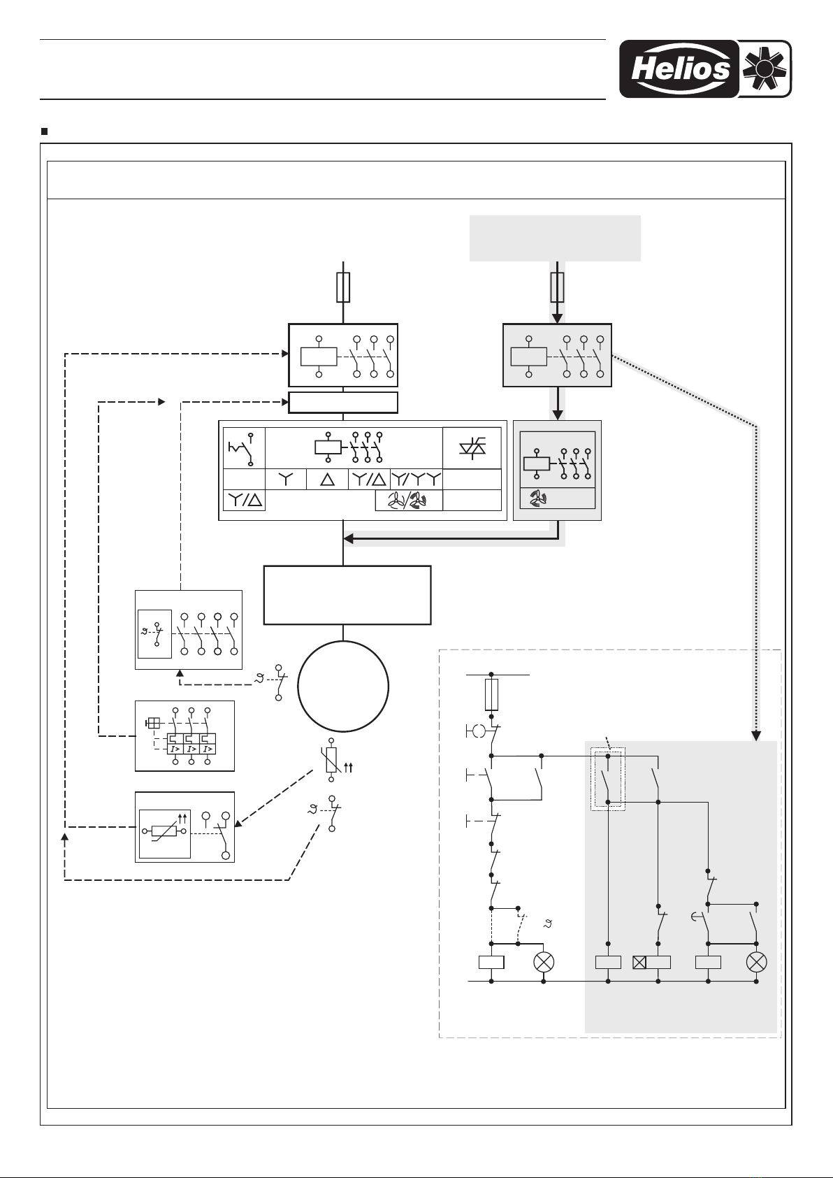
Schaltschema SS-1235, Klemmenkasten für BKD, 3 ~ Stern/Dreieck mit Kaltleiter (PTC)
Brandgas-Kanalventilator Serie BK..

8
Brandgas-Kanalventilator Serie BK..
/ Câblage usine
Enlever les barrettes
Déplacer le fil U2 de la
borne centrale vers la
borne à droite C
Enlever les fils des bornes
C/droite.
U1/gauche, U2/milieu
et
Déplacer le fil U1 de la
borne gauche vers la
borne centrale
Raccorder les fils C et U1
sur la borne centrale.
Raccorder le fil U2 sur la
borne de droite.
Mettre une barrette
entre Z1 / U1
Mettre une barrette
entre Z1 / U2
Bornier ventilateur modifié pour
raccordement séparé
des thermocontacts !
Enlever les barrettes
/ Wiring as supplied
Remove links Remove links
Change wire U2 from
middle to right terminal C
Disconnect wires
C/right
from terminal.
U1/left,
U2/middle and
Change wire U1 from
left to middle terminal.
Connect wire C and U1
to middle terminal, wire
U2 to right terminal.
Put a link between Z1 / U1 Put a link between Z1 / U2
Modified terminal plate for separate connection of thermal contacts.
U2
Z1TK
TK
U1
C
Z2
C
L N
TK Z1 Z2
C
TK U1 U2
1
2
Lieferzustand
U2
Z1TK
TK
U1 C
Z2
C
TK Z1 Z2
C
TK U1 U2
Brücken entfernen
3
U2
Z1TK
TK
U1
C
Z2
C
TK Z1 Z2
C
TK U1 U2 U2
Draht von
mittlere auf rechte
Klemmstelle legen
U2
C
4
Z1TK
TK
U1
Z2
C
TK Z1 Z2
C
TK U1 U2
Draht von linker
auf mittlere
Klemmstelle legen
U1
U1
5
C
U2
Z1TK
Z2
C
TK Z1 Z2
C
U2
Brücke auf /Z1 U1
U1
U1
C
U2
TK
TK
Z1TK
Z2
C
TK Z1 Z2
C
U2
U1
U1
C
U2
TK
TK
L NTKTK
Fertige Anpassung für separaten TK Anschluss !
AB
U2
Z1TK
TK
U1 C
Z2
C
TK Z1 Z2
TK U1 U2
NL
C
U2
Z1TK
TK
U1 C
Z2
C
TK Z1 Z2
TK U1 U2
C
U2
Z1TK
TK
U1
C
Z2
C
TK Z1 Z2
C
TK U1 U2
Draht
/rechts vonC,
U1 U2/links, /mitte
und
Klemmstelle nehmen
Z1TK
TK
Z2
C
TK Z1 Z2
C
TK U1 U2
Draht auf
mittlere Klemmstelle
Draht auf rechte
Klemmstelle legen.
C und U1
,
U2
Z1TK
U2
Z2
C
TK Z1 Z2
C
U1 U2
U1
C
TK
TK
Brücke auf /Z1 U2
Z1TK
U2
Z2
C
TK Z1 Z2
C
U1 U2
U1
C
TK
TK
L NTKTK
92931 001 SS-825 26.03.04
Brücken entfernen
Schaltschema SS-825, Klemmbrettumbau von TK in Reihe auf TK separat
In-line rectangular smoke exhaust fan series BK..
1
INSTALLATION AND OPERATING
INSTRUCTIONS
In order to ensure trouble-free operation and for
your own safety, all of the following instructions
should be carefully observed.
RECEIPT
The shipment must be checked for damage and
correctness immediately upon delivery. If there is
any damage, promptly report the damage with the
assistance of the transport company. If complaints
are not made within the agreed period, any claims
could be lost.
STORAGE
When storing for a prolonged time, the following
steps are to be taken: The storage location must be
Vibration-free, water-tight and free from temperature
fluctuations. Damages due to improper transportati-
on, storage or commissioning must be verified and
are not liable for warranty.
In case of several years of storage or motor stand-
still, the bearings must be inspected and replaced,
if necessary, before commissioning. Electrical testing
must also be carried out according to VDE 0701 or
VDE 0530/ EN 60034.
In case of reshipment (above all, over longer distan-
ces), it must be checked whether the packaging is
suitable for the form and route of transport.
Damages due to improper transportation, storage or
commissioning must be verified and are not liable for
warranty.
AREA OF APPLICATION
The fans are suitable for smoke extraction at air flow
temperatures of 400 °C /120 min. (one-off).
In case of operation under difficult conditions e.g.
high humidity, longer periods of standstill, heavy con-
tamination, excessive loads due to climatic, technical
or electronic influences, further enquiry and release
approval is necessary as the standard version may
not be suitable.
The unit is jet water-protected (IP55) and suitable for
sheltered outdoor installation. The unit must be pro-
tected against the effects of weather. The fan may
only be used according to its intended purpose.
PROTECTION AGAINST CONTACT
The generally applicable safety at work and ac-
cident prevention regulations must be observed
for installation.
Contact with rotating parts must be avoided. It must
be ensured that there are no textiles (e.g. curtains) or
other materials that could be sucked up in the intake
area.
Fans which are protected by their installation method
(e.g. installation in ventilation ducts or closed assem-
blies) do not require protection guards if the plant
provides the same level of safety.
Please note that the installer can be held liable for
accidents as a consequence of missing protection
systems.
SAFETY IN CASE OF FIRE
The available full motor protection or thermal contact
s must be bridged for use in case of fire. This will
ensure fan operation in case of fire.
The unit must be connected to an emergency power
supply.
The mains supply line must be fireproof or installed
outside of the possible fire zone to be protected.
The building inspectorate regulations must be obser-
ved.
FUNCTIONAL RELIABILITY - EMERGENCY
OPERATION
When using the fan in an important technical supply
function, the system must be designed so that emer-
gency operation is automatically guaranteed in case
of fan failure. Suitable solutions include the parallel
operation of two less powerful devices with separa-
te electric circuit, redundancy, alarm systems and
emergency ventilation systems.
ELECTRICAL CONNECTION
ATTENTION: The unit must be fully isolated from
the mains power supply before any maintenance
and installation work.
The electrical connection must only be carried out by
an authorised, qualified electrician. The relevant saf-
ety and installation regulations must be observed. An
all-pole mains switch with at least a 3 mm contact
opening is mandatory.
The motor type plate provides information about the
electrical values; these must be checked for confor-
mity with the local conditions.
The installation and operating instructions for all used
accessory parts must also be observed.
The mains supply line must be inserted so that water
cannot penetrate along the cable in case of water ex-
posure. Never lead cables over sharp edges.
ATTENTION: Incorrect direction of rotation can
lead to the overheating of the motor.
Three phase current types must be connected
by interchanging two phases for anti-clockwise
rotation in case of electrical connection in the
clockwise field of rotation.
MOTOR PROTECTION
Each fan motor must be protected separately against
thermal overload and phase failure by a motor pro-
tection circuit breaker. Motor protection circuit brea-
kers or so-called triggering devices must be used for
correct connection. All motor types used in this se-
ries must be equipped with thermal contacts or PTC
thermistors. They must be connected to the terminal
board and wired with a suitable full motor protection
device (Helios accessories).
The electrical connection must be established so that
the fan is operated until electromechanical failure in
case of smoke extraction. In this respect, each type
of motor protection device must be bridged in case
of smoke extraction and not cause the fan to deac-
tivate.
IMPORTANT: When using as a smoke exhaust
fan, the replacement power supply for automatic
function must be connected bypassing the ther-
mal contacts or PTC thermistors and the full mo-
tor protection device or control unit.
SPEED CONTROL
When using an in-line rectangular smoke exhaust fan
as a smoke extraction fan, speed control is prohibi-
ted.
The electrical connection must be established so
that the fan is operated at nominal speed in case of
smoke extraction. In this respect, each type of speed
controller must be bridged in case of smoke extrac-
tion.
ATTENTION: The use of other brands, especially
other electronic devices, can lead to functional
problems, destruction of the controller and/or the
fan. Control units that have not be approved by
Helios are not liable for warranty and guarantee
claims.
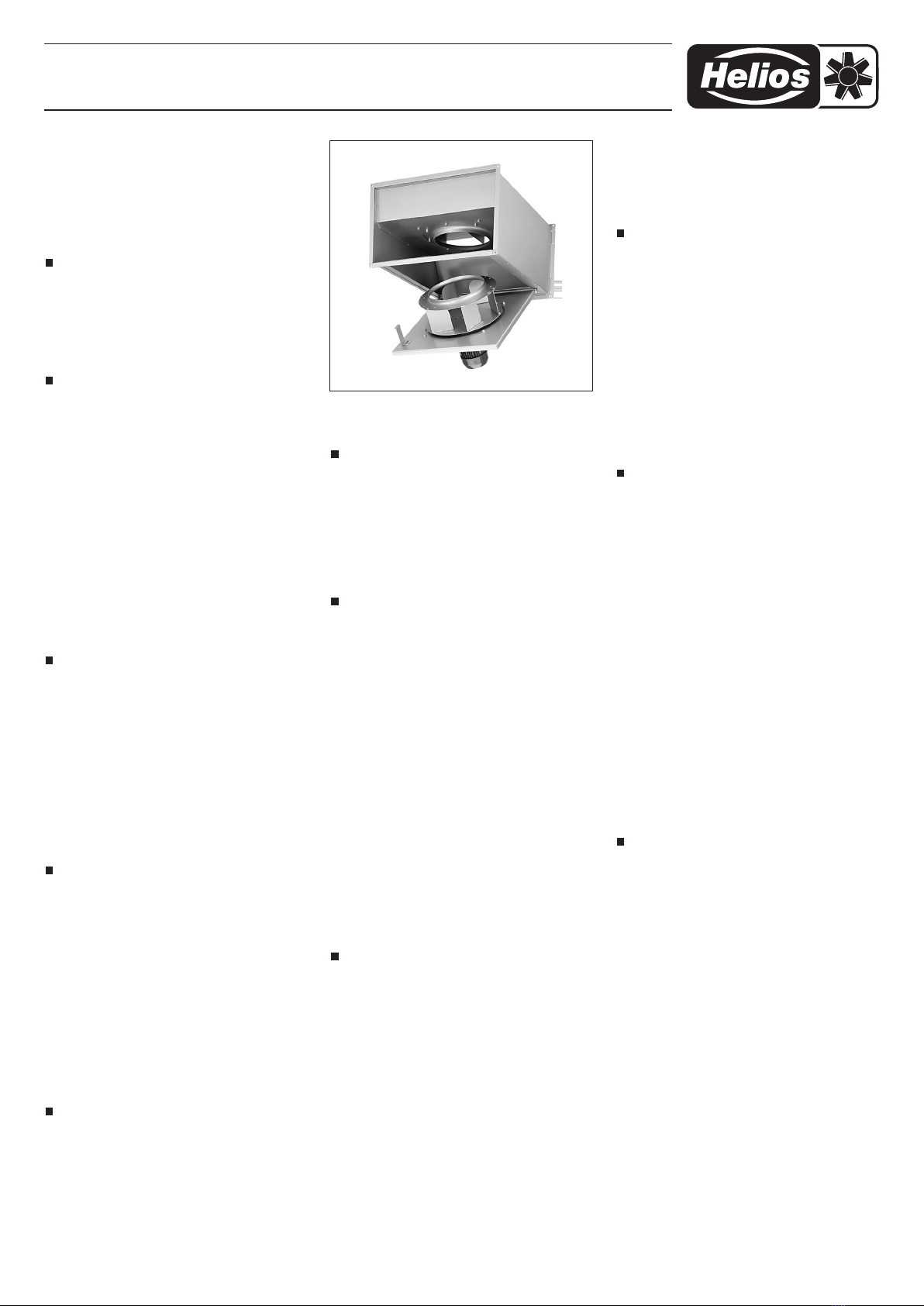
INSTALLATION
The fans are delivered as complete units as standard,
i.e. ready to install.
The swing-out area and ease of access to the mo-
tor-impeller unit must be ensured. When using as a
smoke exhaust fan, the motor may only be mounted
“suspended” in the horizontal mounting position. The
prevention of structure-borne sound transmission
must be ensured during installation. For this purpose,
use flexible connectors (see Accessories) e.g. bet-
ween fan and ducting. Insert suitable screw locks to
prevent loosening.
In case of pipe or duct installation, it must be ensured
that a sufficiently long duct section is installed before
and after the unit, otherwise a significant reduction in
performance and increase in noise levels can be ex-
pected. Devices for collecting and discharging con-
densation and cleaning agents must be provided at
suitable points in the ducting.
The planners and operators must ensure easy ac-
cess for maintenance, inspection and cleaning work.
The necessary space conditions and access possibi-
lities must also be guaranteed for possible fan repla-
cement.
COMMISSIONING
Air flow direction and direction of rotation
The units in series BK.. have a fixed direction of ro-
tation and air flow direction (reverse operation not
possible), which are marked on the units with arrows.
The direction of rotation can be checked on the mo-
tor for installed fans.
Checks:
The following checks are to be carried out:
– check for operation according to the intended pur-
pose of the unit.
– compare power supply voltage with motor rating
plate.
– check that the unit is securely mounted.
– check all parts especially screws, nuts and grilles
for tight fit.
– check free movement of the impeller.
– check if direction of rotation and air flow direction
correspond.
– compare power consumption with data on the ra-
ting plate.
– test functioning of motor protection device (brid-
ging in case of fire).
– test protective conductor connection.
–
check sealing of the connection cable and tight
clamping of the cable wire.

2
In-line rectangular smoke exhaust fan series BK..
– Commissioning may only take place if protection
against contact with the impeller is provided.
INFORMATION / FAULT CAUSES
–
If the thermal overload protection is triggered, this
could be the result of contamination, stiffness of
the impeller and/or bearings. The cause can also
be a winding temperature that is too high due to
insufficient motor cooling, or air flow temperatures
or ambient temperatures that are too high.
– Abnormal noises can be caused by worn out bea-
rings.
– Vibrations can originate from an unbalanced or dir-
ty impeller or due to the installation situation.
MAINTENANCE
ATTENTION: The unit must be fully isolated from
the mains power supply before any maintenance
and installation work.
Excessive deposits of dirt, dust, grease, etc. on the
impeller, motor, protection guard and, above all, bet-
ween the casing and the impeller, are not permitted
and must be prevented by periodic cleaning. The
motor-impeller unit can swing-out for inspection and
cleaning. All parts are freely accessible.
Insofar as the unit has an important technical supply
function, regular six-monthly maintenance is required.
In cases of longer periods of standstill, maintenance
must be carried out when the unit is restarted.
Units which are not regularly operated or are only in-
tended for fire gas operation must be operated for a
minimum of one hour at least every 3 months.
REPAIR WORK
Defective smoke exhaust fans must be completely
replaced. Customer repair attempts are not permis-
sible under any circumstances.
The defective smoke exhaust fan must be fully re-
turned to the Helios Ventilatoren factory!
Contact Helios customer service team.
The unit must be disposed of following smoke
extraction operation!
SOUND LEVELS
The sound levels stated in the catalogue can differ
considerably after installation as the sound pressu-
re level depends on the absorption capacity of the
room, the installation situation and other factors.
Sound reduction is possible by using sound atte-
nuators (available as accessories for certain types).
FAULTS
The thermal contacts/motor protection devices may
be triggered by:
– Heavy contamination, stiffness of the impeller and/
or ball bearing,
– air flow temperature too high,
– too little pressure loss in the duct network.
Abnormal noises can be caused by
– incorrect direction of rotation,
– work out ball bearings.
Vibrations can be caused by:
–
an unbalanced or dirty impeller or the installation
situation.
Heavily reduced performance can occur if:
– the actual duct and component resistances (grille,
dampers, filters, etc.) are higher than planned.
ACCESSORIES, SWITCH AND CONTROL ELE
MENTS
The use of accessory parts, which are not recom-
mended or offered by Helios, is not permitted. Pos-
sible damage will not be covered by warranty.
WARRANTY
If the previous instructions are not observed, our war-
ranty and goodwill treatment will cease to apply. The
same applies to derived liability claims against the
manufacturer.
CERTIFICATION
This unit series has been tested according to DIN EN
12101-3.
REGULATIONS / GUIDELINES
If the unit is installed correctly and used to its inten-
ded purpose, it conforms to all applicable regulations
and CE guidelines.

3
In-line rectangular smoke exhaust fan series BK..
M 3~
PTC
MSA, PTC Überwachung
Electronics for PTC monitoring
Électronique pour PTC surveillance
RHS 6+2
Revisions Hauptschalter
Revision main switches
Révision interrupteur principal
Versorgung Brandfall
Supply for emergency operation
Alimentation de secours
Versorgung, normaler Lüftungsbetrieb
Supply, normal operation
Alimentation, fonctionn. ventilation normale
RHS 6+2*
Revisions
Hauptschalter
K1
K1S1
S0
L1
N
S2
K2
K10
K10
K10
K11T
K2
K2
K1
K11T K2
1sec
Schaltungsvorschlag
Operation recommendation / Consigne de branchement
Prinzip-Steuerung
Principle layout
Principe contrôle
Steuerkontakt
Brandfall-Alarm
Control port contact emergency
Contact de contrôle alarme incendie
Normal-Betrieb
Normal operation
Fonctionn. normal
Ein
On
Marche
Brandfall
Emergency
operation
Cas d' incendie
Alarm
Alarm
Alarme
K1 K2
3~ mit bzw. ohne ThermoschutzBrandgas Ventilatoren
Smoke extract fan / Ventilateurs de désenfumage
DS 2, Aus/Y/D
Manual switch off/Y/
Commutateur manuel arrêt/ Y/
D
D
DS 2 FU
0-100% 100%
PTC
MSA
MD max. 25 A
MD, Motorvollschutzschalter
Motor protection unit
Protection moteur avec TK
FU Frequenzumrichter
Frequency inverters
Variateur de fréquence
85266 001 SS-1023 25.04.12
*mit FU, SS-924 beachten
with FU, follow SS-924
suivre SS-924 avec FU
MSA, MD,
F1,
F1, Motorschutzschalter
motor protection switch
disjoncteur moteur
F1
MD, F1
Wiring diagram SS-1023
4
92614 002 SS-565 25.07.05
K1
K4K3
K2
U1
V1
W1 V2
U2
W2
M 3 ~
mit TK
K2K1
K2S1
S0
L1
N
S2
K3
K4
L1
L1
TK TK U1 V1 W1
L2
L2
L3
L3
L3 L2 L1
V2 U2 W2
MD
(TK)
K10
K10
K10
K11T
K4
K3 K4
K1
K2
K11T K4
1sec
-Betrieb, hohe Drehzahl
high speed /
Fonctionn. pleine vitesse
Brandfall !
Emergency operation / Cas d' incendie
MD / SS-518
Motorvollschutz
mit TK
M 4 / SS-144
Motorvollschutz
Y/ mit TKD DS 2 / SS-87
Aus/Stern/Dreieck
Drehzahlumschalter
Leistungsteil
Schützsteuerung
Y/D
RDS / SS-139
Trafo-Drehzahlst.
mit Motorvollsch. TK
Leistungsteil
Brandfall
RHS 6+2 / SS-505
Revisions
Hauptschalter
M 3 ~
mit TK
Versorgung, normaler Lüftungsbetrieb
Supply, normal operation
Alimentation, fonctionn. ventilation normale
Versorgung Brandfall
Supply for emergency operation
Alimentation de secours
MD
Motor protection unit
Protection moteur avec TK
M 4 Y/
Motor protection with Y/switch
Protection moteur avec Y/ comm.
D
D
D
RDS
Transfomer speed controller
with Motor protection
Transformateur régulateur de
vitesse avec protection moteur TK
DS 2 Aus/Y/
Manual switch off/Y/
Commutateur manuel arrêt/ Y/
D
D
DLeistungsteil Schützst. Y/
Power unit, contactor control Y/
Circuit de puissance, contrôle
circuit contacteur Y/
D
D
D
Leistungsteil Brandfall
Power unit for emergency operation
Circuit de puissance en cas
d' incendie
RHS 6+2
Main switch
Interrupteur principal
Leistungsteil Brandfall, Schaltungsvorschlag / Power unit for emergency operation,
recommendation / Circuit de puissance en cas d' incendie, consigne de branchement
Prinzip-Steuerung
Principle layout
Principe contrôle
Steuerkontakt
Brandfall-Alarm
Control port contact emergency
Contact de contrôle alarme incendie
Normal-Betrieb
Normal operation
Fonctionn. normal
Ein
On
Marche
Brandfall
Emergency
operation
Cas d' incendie
Alarm
Alarm
Alarme
Normal - Betrieb Operation / Fonctionn.
Brandgas Ventilatoren
moke extract fan / Ventilateurs de désenfumage
Zweitourige 3~ mit TK
Two speed s à deux vitesses
Wiring diagram SS-565, motor for BK, 3 ~ AC with thermal contact, BKD connection diagram
In-line rectangular smoke exhaust fan series BK..
5
M
3~
PTC
PTC
MSA / SS-325.1
MSA
PTC Überwachung
Electronics for PTC monitoring
Électronique pour PTC surveillance Schützsteuerung
Circuit for motor control
Circuit pour moteur contrôle
RHS 6+2
Revisions Hauptschalter
Revision main switches
Révision interrupteur principal
Versorgung Brandfall
Supply for emergency operation
Alimentation de secours
Versorgung, normaler Lüftungsbetrieb
Supply, normal operation
Alimentation, fonctionn. ventilation normale
DS 2 / SS-87
Aus/Stern/Dreieck
Schalter manuell
Leistungsteil
Schützsteuerung
RHS 6+2 / SS-505
Revisions
Hauptschalter
K1
K1S1
S0
L1
N
S2
K2
MSA
K10
K10
K10
K11T
K2
K2
K1
K11T K2
1sec
Schaltungsvorschlag
Operation recommendation / Consigne de branchement
Prinzip-Steuerung
Principle layout
Principe contrôle
Steuerkontakt
Brandfall-Alarm
Control port contact emergency
Contact de contrôle alarme incendie
Normal-Betrieb
Normal operation
Fonctionn. normal
Ein
On
Marche
Brandfall
Emergency
operation
Cas d' incendie
Alarm
Alarm
Alarme
K1
K2
Bei Motor ohne PTC,
Brücke anstatt MSA-Öffner
notwendig!
Brandgas VentilatorenEintourige 3~ mit PTC bzw. ohne Thermoschutz
S with PTC avec PTCmoke extract fan / Ventilateurs de désenfumage
DS 2
Aus/Y/D
Manual switch off/Y/
Commutateur manuel arrêt/ Y/
D
D
Brandfall
Emergency operation
Cas d' incendie
92855 001 SS-776
W2 U2 V2KL
U1 V1 W1KL
KLKL L1 L2 L3 PE
W2 U2 V2KL
U1 V1 W1KL
KLKL L1 L2 L3 PE
Kaltleiter/
Thermistor
PTC PTC
Kaltleiter/
Thermistor
400 V 230 V/
690 V 400 V/
K1 K2
DS 2
K1 K2
Normal-Betrieb
92909 002 SS-565.1 04.02.10
Brandfall-Betrieb
Wiring diagram SS-565.1, motor for BK, 3 ~ AC with PTC, BKD connection diagram
In-line rectangular smoke exhaust fan series BK..

6
K1 K2
U1
U2
K1
K1S1
S0
L1
N
S2
K2
K2
K2
MW-H
(TK)
L1TK TK L1 N N
85499 033 SS-1269 12.02.18
1~ 1~
1~
Brandgas Ventilatoren, Thermokontakt separat / Smoke extract fan, thermal contact separate /
Ventilateurs de désenfumage, thermocontact sèparè
MD / SS-518
Motorvollschutz
mit TK
MW-H
Motor protection unit
Protection moteur avec TK
MWS
Transfomer speed controller
with Motor protection unit
Transformateur régulateur de
vitesse avec protection
moteur TK
Manueller Schalter Ein/Aus
Manual switch on/off
Commutateur manuel
marche/arrêt
Schützst. Ein/Aus
Power unit, contactor on/off
Circuit de puissance, contrôle
circuit contacteur marche/arrêt
RHS 3/1
Main switch
Interrupteur principal
MWS / SS-440
Trafo-Drehzahlst.
mit Motorvollsch. TK Manueller
Schalter
Ein / Aus
Schützsteuerung
Ein / Aus
RHS 3+1, Revisions
Hauptschalter
M 1 ~
mit TK
Schaltungsvorschlag / Recommendation / Consigne de branchement
Normal - Betrieb
Operation/Fonctionn.
Brandfall / Emergency
operation /
Cas d' incendie
M 1 ~
mit TK
Prinzip-Steuerung
Principle layout
Principe contrôle
Normal-Betrieb
Normal operation
Fonctionn. normal
Ein
On
Marche
Brandfall
Emergency
operation
Cas d' incendie
Alarm
Alarm
Alarme
Steuerkontakt
Brandfall-Alarm
Control port contact emergency
Contact de contrôle alarme incendie
Versorgung Brandfall
Supply for emergency operation
Alimentation de secours
Versorgung, normaler Lüftungsbetrieb
Supply, normal operation
Alimentation, fonctionn. ventilation normale
K1
K2
Anschlussbeispiel
connection examples
exemples de branchement
SS-1272
Beispiel
example
exemple
SS-1268
Wiring diagram SS-1269, motor for BK, 1~ with thermal contact, BKW connection diagram
In-line rectangular smoke exhaust fan series BK..

7
Wiring diagram SS-1268, terminal box for BKW with thermal contact separate
85499 032 SS-1268 12.02.18
TB TB NL PE
U1
Z1TK
TK
Z2
C
C
U2
(TK) (TK)
Wiring diagram SS-1234, terminal box for BKD, 3 ~ AC with thermal contact
Wiring diagram SS-1235, terminal box for BKD, 3 ~ star/delta with thermistor (PTC)
In-line rectangular smoke exhaust fan series BK..
Print no. 90 766 -000/ 0218
MBV-BK-2018-02
Service and Information
DHELIOS Ventilatoren GmbH & Co · Lupfenstraße 8 · 78056 VS-Schwenningen FHELIOS Ventilateurs · Le Carré des Aviateurs · 157 avenue Charles Floquet · 93155 Le Blanc Mesnil Cedex
CH HELIOS Ventilatoren AG · Tannstrasse 4 · 8112 Otelfingen GB HELIOS Ventilation Systems Ltd. · 5 Crown Gate · Wyncolls Road · Severalls Industrial Park ·
AHELIOS Ventilatoren · Postfach 854 · Siemensstraße 15 · 6023 Innsbruck Colchester · Essex · CO4 9HZ
In-line rectangular smoke exhaust fan series BK..
/ Câblage usine
Enlever les barrettes
Déplacer le fil U2 de la
borne centrale vers la
borne à droite C
Enlever les fils des bornes
C/droite.
U1/gauche, U2/milieu
et
Déplacer le fil U1 de la
borne gauche vers la
borne centrale
Raccorder les fils C et U1
sur la borne centrale.
Raccorder le fil U2 sur la
borne de droite.
Mettre une barrette
entre Z1 / U1
Mettre une barrette
entre Z1 / U2
Bornier ventilateur modifié pour
raccordement séparé
des thermocontacts !
Enlever les barrettes
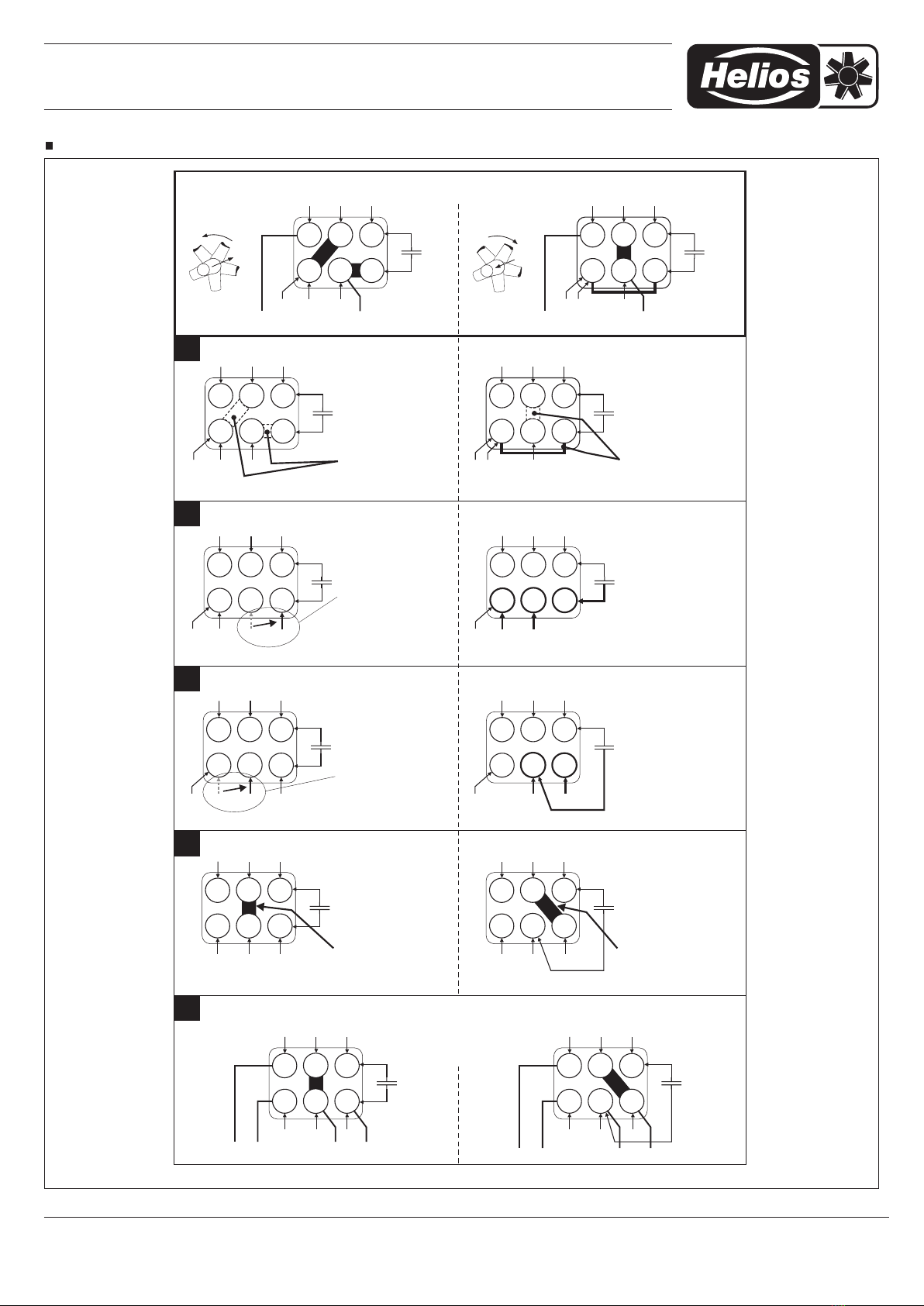
/ Wiring as supplied
Remove links Remove links
Change wire U2 from
middle to right terminal C
Disconnect wires
C/right
from terminal.
U1/left,
U2/middle and
Change wire U1 from
left to middle terminal.
Connect wire C and U1
to middle terminal, wire
U2 to right terminal.
Put a link between Z1 / U1 Put a link between Z1 / U2
Modified terminal plate for separate connection of thermal contacts.
U2
Z1TK
TK
U1 C
Z2
C
L N
TK Z1 Z2
C
TK U1 U2
1
2
Lieferzustand
U2
Z1TK
TK
U1 C
Z2
C
TK Z1 Z2
C
TK U1 U2 Brücken entfernen
3
U2
Z1TK
TK
U1 C
Z2
C
TK Z1 Z2
C
TK U1 U2 U2
Draht von
mittlere auf rechte
Klemmstelle legen
U2
C
4
Z1TK
TK
U1
Z2
C
TK Z1 Z2
C
TK U1 U2
Draht von linker
auf mittlere
Klemmstelle legen
U1
U1
5
C
U2
Z1TK Z2
C
TK Z1 Z2
C
U2 Brücke auf /Z1 U1
U1
U1
C
U2
TK
TK
Z1TK Z2
C
TK Z1 Z2
C
U2
U1
U1
C
U2
TK
TK
L NTKTK
Fertige Anpassung für separaten TK Anschluss !
AB
U2
Z1TK
TK
U1 C
Z2
C
TK Z1 Z2
TK U1 U2
NL
C
U2
Z1TK
TK
U1 C
Z2
C
TK Z1 Z2
TK U1 U2
C
U2
Z1TK
TK
U1 C
Z2
C
TK Z1 Z2
C
TK U1 U2
Draht
/rechts vonC,
U1 U2/links, /mitte
und
Klemmstelle nehmen
Z1TK
TK
Z2
C
TK Z1 Z2
C
TK U1 U2
Draht auf
mittlere Klemmstelle
Draht auf rechte
Klemmstelle legen.
C und U1
,
U2
Z1TK
U2
Z2
C
TK Z1 Z2
C
U1 U2
U1
C
TK
TK
Brücke auf /Z1 U2
Z1TK
U2
Z2
C
TK Z1 Z2
C
U1 U2
U1
C
TK
TK
L NTKTK
92931 001 SS-825 26.03.04
Brücken entfernen
Wiring diagram SS-825, terminal board modification from TK in series to TK separate
Other manuals for BK Series
1
Table of contents
Other Helios Ventilation Hood manuals


