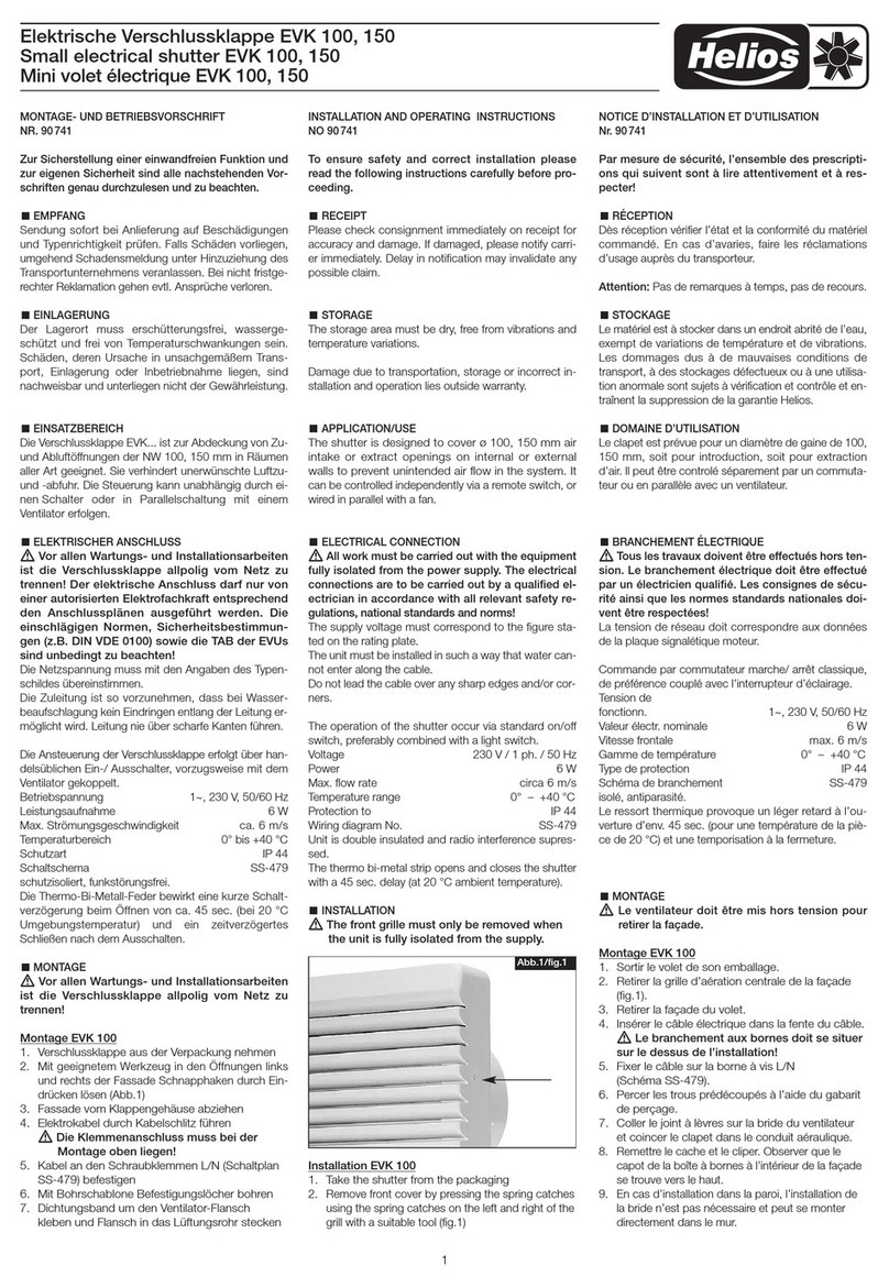
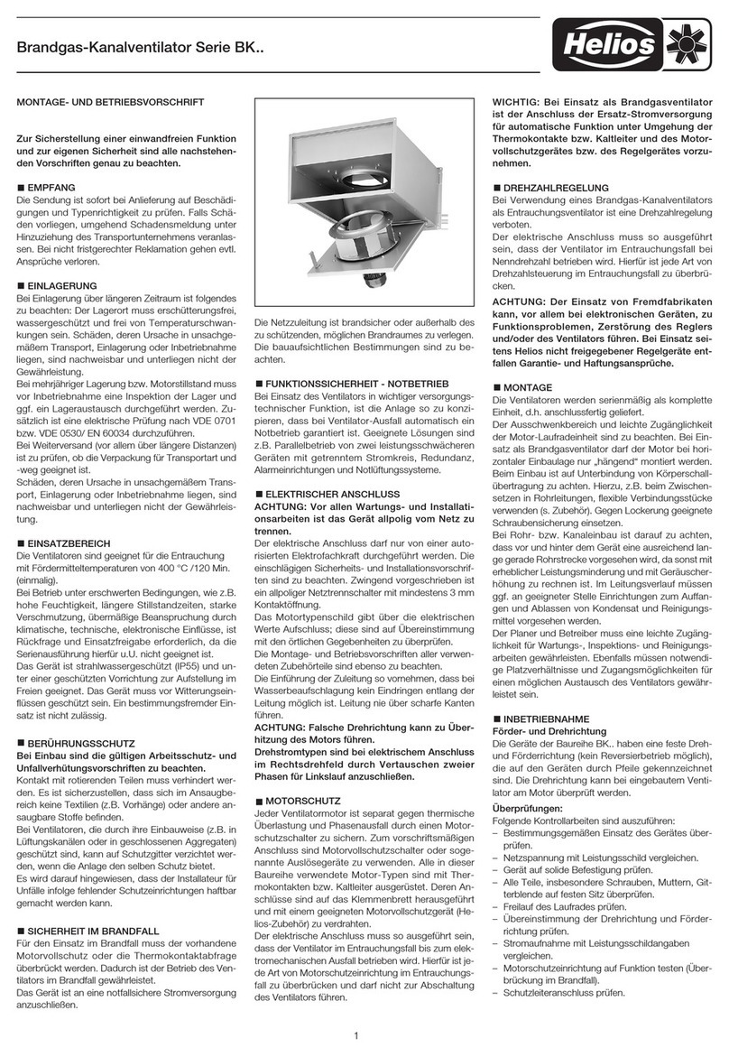
Helios EVK 100 User manual

Elektrische Verschlussklappe EVK 100, 150
Small electrical shutter EVK 100, 150
Mini volet électrique EVK 100, 150
MONTAGE- UND BETRIEBSVORSCHRIFT
NR. 90 741
Zur Sicherstellung einer einwandfreien Funktion und
zur eigenen Sicherheit sind alle nachstehenden Vor-
schriften genau durchzulesen und zu beachten.
EMPFANG
Sendung sofort bei Anlieferung auf Beschädigungen
und Typenrichtigkeit prüfen. Falls Schäden vorliegen,
umgehend Schadensmeldung unter Hinzuziehung des
Transportunternehmens veranlassen. Bei nicht fristge-
rechter Reklamation gehen evtl. Ansprüche verloren.
EINLAGERUNG
Der Lagerort muss erschütterungsfrei, wasserge-
schützt und frei von Temperaturschwankungen sein.
Schäden, deren Ursache in unsachgemäßem Trans-
port, Einlagerung oder Inbetriebnahme liegen, sind
nachweisbar und unterliegen nicht der Gewährleistung.
EINSATZBEREICH
Die Verschlussklappe ist zur Abdeckung von Zu- und
Abluftöffnungen der NW 100, 150 mm in Räumen aller
Art geeignet. Sie verhindert unerwünschte Luftzu- und
-abfuhr. Die Steuerung kann unabhängig durch einen
Schalter oder in Parallelschaltung mit einem Ventilator
erfolgen.
ELEKTRISCHER ANSCHLUSS
ACHTUNG: Alle Arbeiten sind im spannungsfreien
Zustand durchzuführen.
Der elektrische Anschluss darf nur von einer autor.
Elektrofachkraft durchgeführt werden. Die einschlägigen
Sicherheitsvorschriften, Normen (wie VDE 0100, VDE
0530 u. VDE 0700 sowie die TAB’s der EVU’s u. UVV)
sind einzuhalten. Die Netzspannung muss mit den An-
gaben des Typenschildes übereinstimmen.
Die Zuleitung ist so vorzunehmen, dass bei Wasser-
beaufschlagung kein Eindringen entlang der Leitung er-
möglicht wird. Leitung nie über scharfe Kanten führen.
Ansteuerung über handelsüblichen Ein-/ Ausschalter,
vorzugsweise mit dem Ventilator gekoppelt.
Betriebspannung 1~, 230 V, 50/60 Hz
Leistungsaufnahme 8 W
Temperaturbereich 0 ° bis +40 °C
Schutzart IP 44
Schaltschema SS-479
schutzisoliert, funkstörungsfrei.
Die Thermo-Bi-Metall-Feder bewirkt eine kurze Schalt-
verzögerung beim Öffnen von ca. 45 sec. (bei 20 ° C
Umgebungstemperatur) und ein zeitverzögertes
Schließen nach dem Ausschalten.
MONTAGE
Beiliegende Kabeltülle für den verwendeten Kabel-
durchmesser aufschneiden und Kabel durchführen.
Den Montageflansch vom Gehäuse abziehen und
nach dem Montieren der Tülle so an der Wand befe-
stigen, dass der Kabeldurchtritt links oben liegt.
Auf ebene Auflage zur Wand achten!
Die Fassade durch leichtes Eindrücken der Schnapp-
haken links und rechts am Gehäuse lösen (Abb.).
Kabeltülle am Gehäuse durchstechen, Kabel ein-
führen und Gehäuse am Montageflansch mit den bei-
liegenden 2 Schrauben befestigen. Dabei muss der
Klemmenkasten oben liegen. Elektroanschluss aus-
führen und die Fassade wieder so aufstecken und
einrasten lassen, dass die innenliegende Klemmen-
kasten-Abdeckung oben liegt.
Bei Innenwand-Montage kann der Montageflansch
entfallen und das Gehäuse direkt an der Wand befe-
stigt werden.
Die Fassade darf nur entfernt werden, wenn das
Gerät elektrisch spannungsfrei geschaltet ist.
INSTALLATION AND OPERATING INSTRUCTIONS
NO 90 741
To ensure safety and correct installation please
read the following instructions carefully before pro-
ceeding.
RECEIPT
Please check consignment immediately on receipt for
accuracy and damage. If damaged, please notify carri-
er immediately. Delay in notification may invalidate any
possible claim.
STORAGE
The storage area must be dry, free from vibrations and
temperature variations.
Damage due to transportation, storage or incorrect in-
stallation and operation lies outside warranty.
APPLICATION/USE
The shutter is designed to cover ø 100, 150 mm air
intake or extract openings on internal or external
walls to prevent unintended air flow in the system.
It
can be controlled independently via a remote switch, or
wired in parallel with a fan.
ELECTRICAL CONNECTION
WARNING: All work must be carried out with the
equipment fully isolated from the power supply.
The electrical connections are to be carried out by a
qualified electrician in accordance with all relevant sa-
fety regulations, national standards and norms.
The supply voltage must correspond to the figure sta-
ted on the rating plate.
The unit must be installed in such a way that water can-
not enter along the cable.
Do not lead the cable over any sharp edges and/or cor-
ners.
Operation via standard on/off switch, preferably combi-
ned with a light switch.
Voltage 230 V / 1 ph. / 50 Hz
Power 8 W
Temperature range 0 ° – +40 °C
Protection to IP 44
Wiring diagram No. SS-479
Unit is double insulated and radio interference supres-
sed.
The thermo bi-metal strip opens and closes the shutter
with a 45 sec. delay (at 20 ° C ambient temperature)
INSTALLATION
Cut a hole into the enclosed entry gland to suit the ca-
ble diameter and insert the cable. Remove the spacer
frame from the casing and fit the entry gland to the spa-
cer frame which is then to be fitted to the wall with the
cable entry at the top left corner. Ensure the frame is
flush with the surface.
Note: For internal installations the casing can be fixed
straight to the wall without the spacer frame.
Remove the front grille from the casing by carefully
pressing and releasing the clips at both sides (Fig.).
Pierce the entry gland (on the casing), insert the cable
and fix the casing to the spacer with the 2 enclosed
screws. Ensure that the terminal box is at the top. Wire
the electrical connections and replace the front grille in
such a way that the cover for the terminal box (on the
inside of the front grille) is at the top of the unit.
The front grille must only be removed when the
unit is fully isolated from the supply.
NOTICE D’INSTALLATION ET D’UTILISATION
NO. 90 741
Par mesure de sécurité, l’ensemble des prescripti-
ons qui suivent sont à lire attentivement et à res-
pecter!
RÉCEPTION
Dès réception vérifier l’état et la conformité du matériel
commandé. En cas d’avaries, faire les réclamations
d’usage auprès du transporteur.
Attention: Pas de remarques à temps, pas de recours.
STOCKAGE
Le matériel est à stocker dans un endroit abrité de l’eau,
exempt de variations de température et de vibrations.
Les dommages dus à de mauvaises conditions de
transport, à des stockages défectueux ou à une utilisa-
tion anormale sont sujets à vérification et contrôle et en-
traînent la suppression de notre garantie.
DOMAINE D’UTILISATION
Le clapet est prévue pour un diamètre de gaine de 100,
150 mm, soit pour introduction, soit pour extraction
d’air. Il peut être controlé séparement par un commuta-
teur ou en parallèle avec un ventilateur.
BRANCHEMENT ÉLECTRIQUE
ATTENTION: Tous les travaux doivent être effectués
hors tension!
Le branchement électrique doit être effectué par un
électricien qualifié. Les consignes de sécurité ainsi que
les normes standards nationales doivent être respec-
tées. La tension de réseau doit correspondre aux
données de la plaque signalétique moteur.
Commande par commutateur marche/ arrêt classique,
de préférence couplé avec l’interrupteur d’éclairage.
Tension de
fonctionn. 1~, 230 V, 50/60 Hz
Valeur électr. nominale 8 W
Gamme de température 0 ° – +40 °C
Type de protection IP 44
Schéma de branchement SS-479
isolé, antiparasité.
Le ressort thermique provoque un léger retard à l’ou-
verture d’env. 45 sec. (pour une température de la piè-
ce de 20 ° C) et une temporisation à la fermeture.
MONTAGE
Suivant le diamètre du cable découper le passe cable
et introduire le fil. Enlever la plaque de montage, passer
le passe cable par le trou dans la façe d’appuis. Monter
sur le mur en placant le passe cable en haut à gauche.
Enlever la façade du clapet en appuyant sur les clips à
droite et à gauche de l’appareil. Monter le passe cable
sur le clapet et fixer la bride de celui-ci à l’aide des deux
vis. La boîte de raccordement doit étre située lur le
haut.
Effectuer le raccordement électrique et remplacer la
façade. En cas d’un montage sur un mur intérieur, l’uti-
lisation de le plaque de montage n’est pas nécessaire
et le clapet peut être monté directement sur le mur.
Le ventilateur doit être mis hors tension pour retirer
la façade.

Druckschrift-Nr. 90 741/ 12.06
Elektrische Verschlussklappe EVK 100, 150
Small electrical shutter EVK 100, 150
Mini volet électrique EVK 100, 150
Montageschablone / Installation Pattern / Gabarit d’assemblage
SS-479
Mit geeignetem Werkzeug in den
Öffnungen links und rechts der
Fassade Schnapphaken durch
leichtes Eindrücken lösen.
Blende wieder aufstecken und ein-
rasten lassen. Hierbei ist zu beach-
ten, dass sich die innen in der
Fassade befindlichen Klemmen-
kasten-Abdeckung oben befindet.
Remove the cover by using the
correct tool and applying light
pressure on the spring catches in
the openings left and right of the
cover.
Put the cover in the correct place
and snap in. Thereby please take
care that the wiring box cover is
over the wiring box.
A l’aide d’outillage approprié, reti-
rer la façade en pressant le crochet
d’enclenchement dans les trous
d’ouverture côtés droit et gauche.
Refixer tout simplement la façade
en réenclenchant le crochet. Ob-
server que le capot de la boîte à
bornes à l’intérieur de la façade se
trouve vers le haut.
GARANTIEANSPRÜCHE – HAFTUNGSAUS-
SCHLUSS
Wenn die vorausgehenden Ausführungen nicht beach-
tet werden, entfällt unsere Gewährleistung und Be-
handlung auf Kulanz. Gleiches gilt für abgeleitete Haf-
tungsansprüche an den Hersteller.
VORSCHRIFTEN – RICHTLINIEN
Bei ordnungsgemäßer Installation und bestimmungs-
gemäßem Betrieb entspricht das Gerät den zum Zeit-
punkt seiner Herstellung gültigen Vorschriften, Richt-
linien CE.
WARRANTY – EXCLUSION OF
LIABILITY
If the preceding instructions are not observed all war-
ranty claims are void.
The Helios warranty is limited to the material and
workmanship of the product.
CERTIFICATES
If installed correctly the product complies with rele-
vant European standards and regulations as at the
time of its manufacture.
DEMANDE DE GARANTIE – RÉSERVES DU CON-
STRUCTEUR
En cas de non-respect des indications précédentes,
toute demande de remplacement ou de réparation à ti-
tre gratuit sera déclinée. Il en sera de même pour toute
implication de responsabilité du fabricant.
RÉGLEMENTATIONS – NORMES
Si la notice d’installation et d’utilisation est observée,
nos produits correspondent aux normes et réglementa-
tions européennes.
Service und Information
DHELIOS Ventilatoren GmbH & Co · Lupfenstraße 8 · 78056 VS-Schwenningen FHELIOS Ventilateurs · Z.I. La Fosse à la Barbière · 2, rue Louis Saillant · 93605 Aulnay sous Bois Cedex
CH HELIOS Ventilatoren AG · Steinackerstraße 36 · 8902 Urdorf / Zürich GB HELIOS Ventilation Systems Ltd. · 5 Crown Gate · Wyncolls Road · Severalls Industrial Park ·
AHELIOS Ventilatoren · Postfach 854 · Siemensstraße 15 · 6023 Innsbruck Colchester · Essex · CO4 9HZ
This manual suits for next models
1
Other Helios Ventilation Hood manuals
