Helios EVK 100 User manual
INSTALLATI N AND PERATING INSTRUCTI NS
N 90 741
To ensure safety and correct installation please
read the following instructions carefully before pro-
ceeding.
RECEIPT
Please check consignment immediately on receipt for
accu racy and damage. If damaged, please notify carri-
er immediately. Delay in notification may invalidate any
possible claim.
ST RAGE
The storage area must be dry, free from vibrations and
temperature variations.
Damage due to transportation, storage or incorrect in-
stallation and operation lies outside warranty.
APPLICATI N/USE
The shutter is designed to cover ø 100, 150 mm air
intake or extract openings on internal or external
walls to prevent unintended air flow in the system.
It
can be controlled independently via a remote switch, or
wired in parallel with a fan.
ELECTRICAL C NNECTI N
All work must be carried out with the equipment
fully isolated from the power supply. The electrical
connections are to be carried out by a qualified el-
ectrician in accordance with all relevant safety re-
gulations, national standards and norms!
The supply voltage must correspond to the figure sta-
ted on the rating plate.
The unit must be installed in such a way that water can-
not enter along the cable.
Do not lead the cable over any sharp edges and/or cor-
ners.
The operation of the shutter occur via standard on/off
switch, preferably combined with a light switch.
Voltage 230 V / 1 ph. / 50 Hz
Power 6 W
Max. flow rate circa 6 m/s
Temperature range 0° – +40 °C
Protection to IP 44
Wiring diagram No. SS-479
Unit is double insulated and radio interference supres-
sed.
The thermo bi-metal strip opens and closes the shutter
with a 45 sec. delay (at 20 °C ambient temperature).
INSTALLATI N
The front grille must only be removed when
the unit is fully isolated from the supply.
Installation EVK 100
1. Take the shutter from the packaging
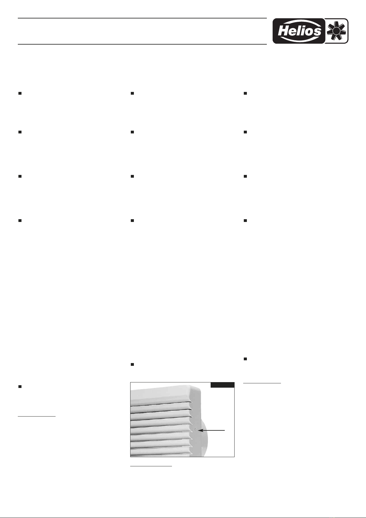
2. Remove front cover by pressing the spring catches
using the spring catches on the left and right of the
grill with a suitable tool (fig.1)
Elektrische Verschlussklappe EVK 100, 150
Small electrical shutter EVK 100, 150
Mini volet électrique EVK 100, 150
1
M NTAGE- UND BETRIEBSV R SCHRIFT
NR. 90 741
Zur Sicherstellung einer einwandfreien Funktion und
zur eigenen Sicher heit sind alle nachstehenden Vor -
schriften genau durchzulesen und zu beachten.
EMPFANG
Sendung sofort bei Anlieferung auf Be schä digungen
und Typenrichtigkeit prüfen. Falls Schäden vorliegen,
umgehend Schadensmeldung unter Hin zu zieh ung des
Transportunternehmens ver anlas sen. Bei nicht fristge-
rechter Re klama tion gehen evtl. An sprüche ver loren.
EINLAGERUNG
Der Lagerort muss erschütterungsfrei, wasserge-
schützt und frei von Tem pe ra tur schwankungen sein.
Schäden, deren Ursache in unsach ge mäßem Trans -
port, Einlage rung oder In betriebnahme liegen, sind
nach weisbar und unterliegen nicht der Gewähr lei stung.
EINSATZBEREICH
Die Verschlussklappe EVK... ist zur Abdeckung von Zu-
und Abluftöffnungen der NW 100, 150 mm in Räumen
aller Art geeignet. Sie verhindert unerwünschte Luftzu-
und -abfuhr. Die Steuerung kann unabhängig durch ei-
nen Schalter oder in Parallel schaltung mit einem
Ventilator erfolgen.
ELEKTRISCHER ANSCHLUSS
Vor allen Wartungs- und Installationsarbeiten
ist die Verschlussklappe allpolig vom Netz zu
trennen! Der elektrische Anschluss darf nur von
einer autorisierten Elektrofachkraft entsprechend
den Anschlussplänen ausgeführt werden. Die
einschlägigen Normen, Sicherheitsbestimmun-
gen (z.B. DIN VDE 0100) sowie die TAB der EVUs
sind unbedingt zu beachten!
Die Netzspannung muss mit den An ga ben des Typen -
schildes über ein stim men.
Die Zuleitung ist so vorzunehmen, dass bei Wasser -
beaufschlagung kein Ein dringen entlang der Leitung er-
möglicht wird. Leitung nie über scharfe Kanten führen.
Die Ansteuerung der Verschlussklappe erfolgt über han-
delsüblichen Ein-/ Ausschalter, vorzugsweise mit dem
Ven tilator gekoppelt.
Betriebspannung 1~, 230 V, 50/60 Hz
Leistungsaufnahme 6 W
Max. Strömungsgeschwindigkeit ca. 6 m/s
Temperaturbereich 0° bis +40 °C
Schutzart IP 44
Schaltschema SS-479
schutzisoliert, funkstörungsfrei.
Die Thermo-Bi-Metall-Feder bewirkt eine kurze Schalt -
verzögerung beim Öffnen von ca. 45 sec. (bei 20 °C
Umgebungs tem pe ratur) und ein zeitverzögertes
Schließen nach dem Ausschalten.
M NTAGE
Vor allen Wartungs- und Installationsarbeiten
ist die Verschlussklappe allpolig vom Netz zu
trennen!
Montage EVK 100
1. Verschlussklappe aus der Verpackung nehmen
2. Mit geeignetem Werkzeug in den Öff nun gen links
und rechts der Fassade Schnapphaken durch Ein-
drücken lösen (Abb.1)
3. Fassade vom Klappengehäuse abziehen
4. Elektrokabel durch Kabelschlitz führen
Die Klem men anschluss muss bei der
Montage oben liegen!
5. Kabel an den Schraubklemmen L/N (Schaltplan
SS-479) befestigen
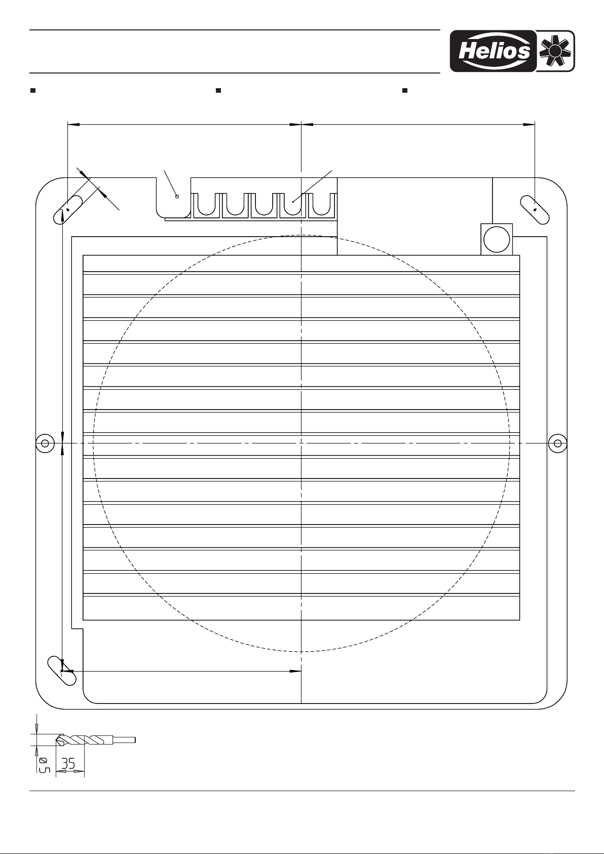
6. Mit Bohrschablone Befestigungslöcher bohren
7. Dichtungsband um den Ventilator-Flansch
kleben und Flansch in das Lüftungsrohr stecken
N TICE D’INSTALLATI N ET D’UTILISATI N
Nr. 90 741
Par mesure de sécurité, l’ensemble des prescripti-
ons qui suivent sont à lire attentivement et à res -
pecter!
RÉCEPTI N
Dès réception vérifier l’état et la conformité du ma té riel
commandé. En cas d’avaries, faire les réclamations
d’usage auprès du transporteur.
Attention: Pas de remarques à temps, pas de recours.
ST CKAGE
Le matériel est à stocker dans un endroit abrité de l’eau,
exempt de variations de température et de vibrations.
Les dom ma ges dus à de mauvaises con ditions de
transport, à des stockages défec tueux ou à une utilisa-
tion anor male sont sujets à vérification et contrôle et en -
traî nent la suppression de la garantie Helios.
D MAINE D’UTILISATI N
Le clapet est prévue pour un diamètre de gaine de 100,
150 mm, soit pour introduction, soit pour extraction
d’air. Il peut être controlé séparement par un commuta-
teur ou en parallèle avec un ventilateur.
BRANCHEMENT ÉLECTRIQUE
Tous les travaux doivent être effectués hors ten-
sion. Le branchement électrique doit être effectué
par un électricien qualifié. Les consignes de sécu-
rité ainsi que les normes standards nationales doi-
vent être respectées!
La tension de réseau doit correspondre aux données
de la plaque signalétique moteur.
Commande par commutateur marche/ arrêt classique,
de préférence couplé avec l’interrupteur d’éclairage.
Tension de
fonctionn. 1~, 230 V, 50/60 Hz
Valeur électr. nominale 6 W
Vitesse frontale max. 6 m/s
Gamme de température 0° – +40 °C
Type de protection IP 44
Schéma de branchement SS-479
isolé, antiparasité.
Le ressort thermique provoque un léger retard à l’ou-
verture d’env. 45 sec. (pour une température de la piè-
ce de 20 °C) et une temporisation à la fermeture.
M NTAGE
Le ventilateur doit être mis hors tension pour
retirer la façade.
Montage EVK 100
1. Sortir le volet de son emballage.
2.
Retirer la grille d’aération centrale de la façade
(fig.1).
3. Retirer la façade du volet.
4. Insérer le câble électrique dans la fente du câble.
Le branchement aux bornes doit se situer
sur le dessus de l’installation!
5. Fixer le câble sur la borne à vis L/N
(Schéma SS-479).
6. Percer les trous prédécoupés à l’aide du gabarit
de perçage.
7. Coller le joint à lèvres sur la bride du ventilateur
et coincer le clapet dans le conduit aéraulique.
8. Remettre le cache et le cliper. b server que le
capot de la boîte à bornes à l’inté rie ur de la façade
se trouve vers le haut.
9. En cas d’installation dans la paroi, l’installation de
la bride n’est pas nécessaire et peut se monter
directement dans le mur.
Abb.1/fig.1

Elektrische Verschlussklappe EVK 100, 150
Small electrical shutter EVK 100, 150
Mini volet électrique EVK 100, 150
2
8. Blende wieder aufstecken und einrasten lassen.
Hierbei ist zu beachten, dass sich die innen in der
Fassade be find lichen Klemmen kasten-Ab dec kung
oben befindet.
9.
Bei Innenwand-Montage kann der Mon tage-
flansch entfallen und das Gehäuse direkt an der
Wand befestigt werden.
Montage EVK 150
1. Verschlussklappe aus der Verpackung nehmen
2. Das mittlere Lüftungsgitter von der Fassade ab-
ziehen (Abb.2)
3. Befestigungsschrauben der Fassade lösen
(Abb.3/4)
4. Fassade vom Klappengehäuse abziehen (Abb.5)
5. Elektrokabel durch Kabelschlitz führen (Abb.6)
Die Klem men anschluss muss bei der
Montage unten liegen!
6. Kabel an den Schraubklemmen L/N (Schaltplan
SS-479) befestigen (Abb.7)
7. Mit Bohrschablone Befestigungslöcher bohren
8. Dichtungsband um den Ventilator-Flansch
kleben und Klappengehäuse in das Lüftungsrohr
stecken.
9. Mit Dübeln (bauseits) an der Wand montieren
10.Fassade auf Grundgehäuse stecken, einrasten
und wieder verschrauben
11.Lüftungsgitter aufstecken und einrasten
GARANTIEANSPRÜCHE – HAFTUNGS AUS -
SCHLUSS
Wenn die vorausgehenden Aus füh run gen nicht beach-
tet werden, entfällt unsere Gewährleistung und Be -
hand lung auf Kulanz. Gleiches gilt für abgeleitete Ha f -
tungs ansprüche an den Hersteller.
V RSCHRIFTEN – RICHTLINIEN
Bei ordnungsgemäßer Installation und bestimmungs -
ge mäßem Betrieb entspricht das Gerät den zum Zeit -
punkt seiner Herstellung gültigen Vorschriften, Richt -
linien CE.
3. Insert electrical cable through cable slot.
Ensure that the terminal connection at the
assembly is at the top!
4. Attach cable to the screw terminals L / N (wiring
diagram SS-479)
5. Drill with drilling template mounting holes.
6. Place sealant tape around the fan flange and
insert flange to the ventilation duct
7. Put the cover in the correct place and snap in.
Thereby please take care that the cover for the
terminal box (on the inside of the front cover) is at
the top of the unit.
8. If mounted to an inner wall the mounting flange can
be omitted and the casing is mounted directly
on the wall.
Installation EVK 150
1. Take the shutter from the packaging
2. Remove air grill of the front panel. (fig.2)
3. Loosen the mounting screws of the front panel
(fig.3/4)
4. Remove front panel of shutter casing (fig.5)
5. Insert electrical cable through cable slot. (fig.6)
Ensure that the terminal connection at the
assembly is at the bottom!
6. Attach cable to the screw terminals L / N (wiring
diagram SS-479) (fig.7)
7. Drill with drilling template mounting holes.
8. Place sealant tape around the fan flange and
insert shutter casing in the ventilation duct
9. Mount to the wall with rawplugs (on site).
10.Replace front panel on shutter casing, press into
place and screw together again
11.Replace air grille and press into place
WARRANTY – EXCLUSI N F
LIABILITY
If the preceding instructions are not observed all war-
ranty claims are void.
The Helios warranty is limited to the material and
workmanship of the product.
CERTIFICATES
If installed correctly the product complies with rele-
vant European standards and regulations as at the
time of its manufacture.
Montage EVK 150
1. Sortir le volet de son emballage.
2. Retirer la grille d’aération centrale de la façade
(fig.2).
3. Retirer les vis de fixation de la façade (fig.3/4).
4. Retirer la façade du volet (fig.5) .
5. Insérer le câble électrique dans la fente du câble.
Le branchement aux bornes doit se situer
sur le dessus de l’installation!
6. Fixer le câble sur la borne à vis L/N
(SS-479) (fig7).
7. Percer les trous prédécoupés à l’aide du gabarit
de perçage.
8. Coller le joint à lèvres sur la bride du ventilateur
et coincer le clapet dans le conduit aéraulique.
9. Fixer sur le mur à l’aide de vis (fourniture client).
10.Coincer le coffre sur la façade et revisser.
11.Insérer la grille d’aération et cliper.
DEMANDE DE GARANTIE – RÉSERVES DU C N-
STRUCTEUR
En cas de non-respect des indications précédentes,
toute demande de remplacement ou de réparation à ti-
tre gratuit sera déclinée. Il en sera de même pour toute
implication de responsabilité du fabricant.
RÉGLEMENTATI NS – N RMES
Si la notice d’installation et d’utilisation est observée,
nos produits correspondent aux normes et réglementa-
tions européennes.
Abb.2/fig.2
Abb.5/fig.5
Abb.3/fig.3 Abb.4/fig.4
Abb.6/fig.6 Abb.7/fig.7

M
ontagebohrschablone EVK 100
SCHALTPLAN SS-479
Reihenklemme 1/2 bzw. L/N
Gabarit d’assemblage EVK 100
SCHÉMA DE CIRCUITS SS-479
Bornier L/N
Installation Pattern EVK 100
WIRING DIAGRAM SS-479
Standard life-neutral L/N connection
Elektrische Verschlussklappe EVK 100, 150
Small electrical shutter EVK 100, 150
Mini volet électrique EVK 100, 150
3
òJò
òLFBNòòKJBMò
òKKBMòòKKBMò
òLGBNò
awx{zy~|~}
ywx{ò{
{{{òz{òywx{
[{wy~
{{yywòy{y
hwyyz{{ò{y{
SS-479
Elektrische Verschlussklappe EVK 100, 150
Small electrical shutter EVK 100, 150
Mini volet électrique EVK 100, 150
Druckschrift-Nr. 90 741/ 03.14
òNIBJò
òNGBIòòNGBIò
òNGBIò
òMOBHò
òJBJò
awx{zy~|~}
ywx{ò{
{{{òz{òywx{
[{wy~
{{yywòy{y
hwyyz{{ò{y{
Service und Information
D HELI S Ventilatoren GmbH + Co KG · Lupfenstraße 8 · 78056 VS-Schwenningen F HELI S Ventilateurs · Le Carré des Aviateurs · 157 ave. Charles Floquet · 93155 Le Blanc Mesnil Cedex
CH HELI S Ventilatoren AG · Steinackerstraße 36 · 8902 Urdorf GB HELI S Ventilation Systems Ltd. · 5 Crown Gate · Wyncolls Road · Severalls Industrial Park ·
A HELI S Ventilatoren · Postfach 854 · Siemensstraße 15 · 6023 Innsbruck Colchester · Essex · C 4 9HZ
M
ontagebohrschablone EVK 150 Installation Pattern EVK 150 Gabarit d’assemblageEVK 150
This manual suits for next models
1
Other Helios Ventilation Hood manuals


Popular Ventilation Hood manuals by other brands


Miele
Miele DA 399-6 Operating and installation instructions

Swegon
Swegon WISE WS a Instructions for use

Lamona
Lamona HJA2450 User's installation guide

Berbel
Berbel Smartline BWH 90 ST Operating and installation instructions

Electrolux
Electrolux RH30WC55GSA Factory parts catalog

Atag
Atag WS90211JM Instructions for use