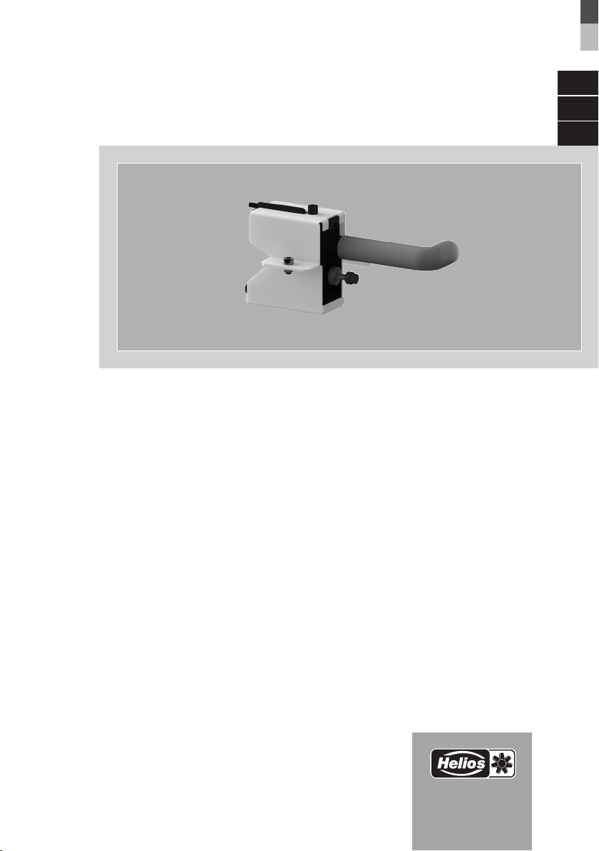
Pompe à condensat AIR1-KP
Notice de montage et d’utilisation
1.0 Informations importantes
Il est important de bien lire et suivre l’ensemble des consignes suivantes pour le bon
fonctionnement de l’appareil et pour la sécurité des utilisateurs. Les normes nationales,
les conditions de sécurité et les réglementations (la norme NF C15-100 par ex.) ainsi
que les conditions techniques de raccordement de la société d’approvisionnement en
électricité sont à respecter et à appliquer impérativement.
Garder la notice à proximité de l’appareil. Après le montage final, le document doit être
remis à l’utilisateur (locataire / propriétaire).
1.1 Précautions et consignes de sécurité
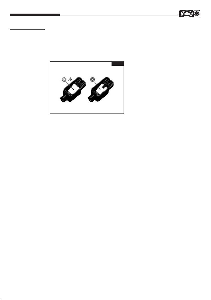
Les symboles ci-contre indiquent une consigne de sécurité. Toutes les consignes
de sécurité ainsi que les symboles doivent être impérativement respectés, afin
d’éviter tout danger.
1.2 Demandes de garantie – Réserves du constructeur
Si les consignes indiquées dans cette notice ne sont pas correctement respectées, la
garantie s’annule. Il en est de même pour toute implication de responsabilité du fabricant.
L’utilisation d’accessoires non conseillés ou proposés par Helios n’est pas permise. Les
dégâts causés par cette mauvaise utilisation ne sont pas couverts par la garantie.
1.3 Règlementations – Normes
Sous réserve d’une installation et d’une utilisation appropriées, ce produit est conforme
à la réglementation et aux directives CE en vigueur le jour de sa fabrication.
1.4 Réception de la marchandise
Dès réception, vérifier l’état et la conformité du matériel commandé. En cas de dé-
gâts, les signaler immédiatement en mentionnant le nom du transporteur. Attention, le
non-respect de ces procédures peut entraîner le rejet de la réclamation.
1.5 Stockage
Pour un stockage de longue durée et pour éviter toute détérioration préjudiciable, il
convient de se conformer aux instructions suivantes :
Protéger avec un emballage sec, étanche à l’air et à la poussière (sac en matière syn-
thétique contenant des sachets déshydrateurs et un indicateur d’humidité). Stocker le
matériel dans un endroit abrité de l’eau, exempt de vibrations et de variations de tempé-
ratures excessives (- 20 à + 60 °C). Les dommages dus à de mauvaises conditions de
transport ou de stockage ou à une utilisation anormale sont décelables et ne sont pas
couverts par la garantie.
1.6 Utilisation conforme
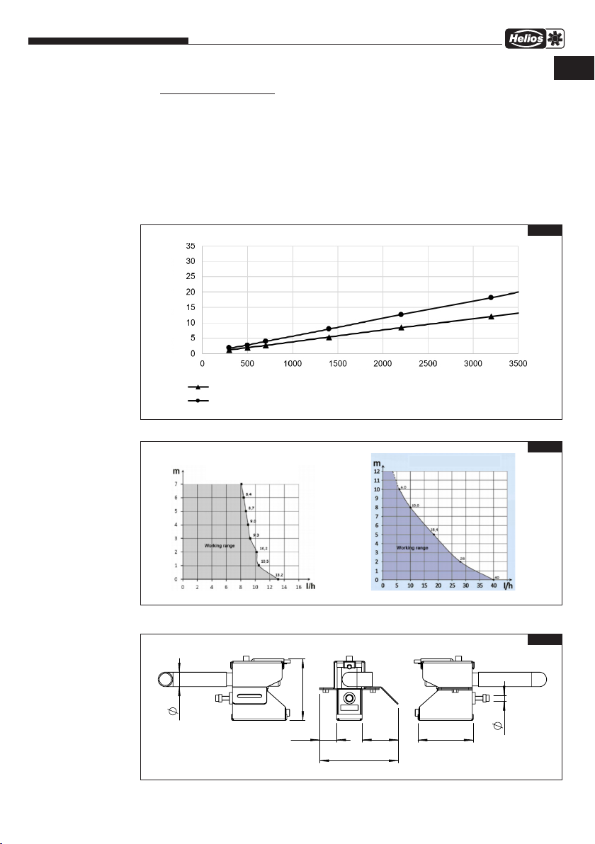
La pompe à condensat permet d’évacuer facilement les condensats du conduit des conden-
sats et de les amener à une certaine hauteur.
La pompe à condensat AIR1-
KP
peut être raccordée aux centrales AIR1 XC ainsi qu’aux
batteries de refroidissement correspondantes (programme Helios).
Tout usage inapproprié est interdit !
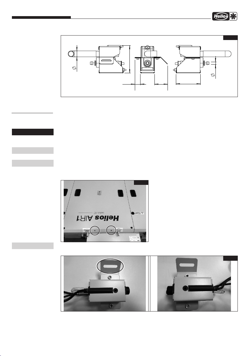
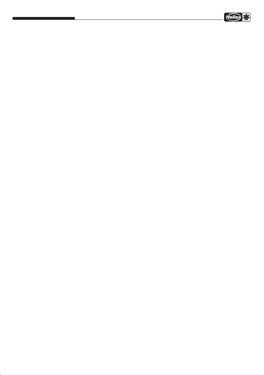
2.0 Données techniques
AIR1-KP XC 500-1400
Débit de refoulement max. 13 l/h
Hauteur d’aspiration max. 1,5 m
Hauteur de refoulement max. 10 m
Alimentation électrique 19 W
Tension 220 – 240 V 50/60 Hz
Température de fonctionnement 5 – 45 °C
Température max. de l’eau 35 °C
Indice de protection IP20
CHAPITRE 1
GÉNÉRALITÉS
REMARQUES
m
ATTENTION m
CHAPITRE 2
DONNÉES
TECHNIQUES
FR
1