Lafferty 920105 Installation instructions

Lafferty Equipment Manufacturing, LLC
Installation & Operation Instructions
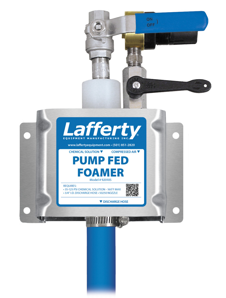
Model # 920105 · Pump Fed Foamer
# 224150
# 491409
# 491411
# 491348SS-T
# 150350-1
# 491306
# 536603-X
REQUIREMENTS
Ready-to-Use Chemical Solution
Temperature up to 160°F
Pressure 35 to 125 PSI
Flow 1.7 GPM @ 40 PSI
Supply Line 1/2"
Compressed Air up to 3 CFM
Hose 3/4" ID x 50'
Nozzle 50250
OPTIONS
Stainless Steel Hose Racks
Large Stainless Steel Hose Rack
Foam Solution Check Valves & Strainer
Check Valve, PP, 1/2'' (EPDM)
Check Valve, PP, 1/2'' (Viton)
Check Valve, 316SS, 1/2", MF (Teflon)
Strainer, "Y", SS, 1/2" MF
Alternate Air Check Valve - EPDM Standard
Check Valve, Air, SS, 1/4" MM (Viton /
Hast)
Stainless Steel Foam Wand (Upgrade)
Convert PP Wand to SS (New Units)
WEIGHT & DIMENSIONS
Single Package
Shipping Weight 23 lbs.
Shipping Dimensions 27" x 19" x 9"
www.laffertyequipment.com
501-851-2820
OVERVIEW
The Pump Fed Foamer is a medium volume foam applicator for projecting ready-to-use foaming chemicals on to any surface up close or at distances up to 12 feet.
This unit receives ready-to-use chemical solution from a central chemical feed system and creates rich, clinging foam by injecting compressed air into the solution to
greatly increase volume and coverage ability. The foam is then projected through the discharge hose, wand and fan nozzle.
W AR N I N G ! R E A D A L L
I N S T R U C T I O N S B E F O R E
U S I N G E Q U I P M E N T !
Lafferty Equipment Manufacturing, LLC • 5614 Oak Grove Road • North Little Rock, Arkansas 72118

SAFETY & OPERATIONAL PRECAUTIONS
For proper performance do NOT modify, substitute nozzle, hose diameter or length.
Manufacturer assumes no liability for the use or misuse of this unit.
Wear protective clothing, gloves and eye-wear when working with chemicals.
Always direct the discharge away from people and electrical devices.
For pressures over 100 PSI, remove the discharge valve or lower pressure
Follow the chemical manufacturer’s safe handling instructions.
Turn off solution supply and air when unit is not in use for extended periods.
TO INSTALL (REFER TO DIAGRAM ON NEXT PAGE)
A check valve is required on the foamer solution inlet to prevent air from going back into the solution line. (See
Options)
1. Mount the unit to a suitable surface.
2. Connect the discharge hose as shown in the diagram and close the ball valve.
3. Install a solution check valve on the foamer solution inlet and connect pre-mixed solution supply.
4. To prevent blocking the small jets flush any new plumbing of debris before connecting. And/or install a strainer.
(see options)
5. Connect compressed air supply. If piping is older and has known contaminants, install a filter.
TO OPERATE
1. With wand in hand open the inlet ball valve, and the air ball valve.
Wait a few seconds and observe foam consistency.
Use the least amount of air needed to achieve good foam quality to prevent solution pressure
fluctuations from affecting performance. Air pressure must be kept lower than solution pressure.
To adjust the foam consistency pull out on the air regulator knob, turn slightly clockwise for dryer foam
and counterclockwise for wetter foam. Wait a few seconds to see each adjustment.
Medium wet foam will give the best cleaning results! Dry foam will NOT clean as well!
You may also have to try different chemical ratios and air settings until foam consistency and cleaning
results are acceptable. Once this is set and desired foam consistency is achieved push lock the knob.
you are ready to start application.
2. When foaming is completed, close the discharge ball valve, return to the unit and close the solution and air ball
valves. Briefly re-open the discharge ball valve to relieve pressure in the hose. Rinse before the foam dries.
UNIT FLOW RATES
PSI GPM
35 1.59
40 1.70
50 1.90
60 2.08
70 2.25
80 2.40
90 2.55
100 2.69
110 2.82
120 2.94
125 3.01
920105 • Pump Fed Foamer
- Page 2 -

920105 • Pump Fed Foamer
- Page 3 -

Troubleshooting Guide
Problem Possible Cause / Solution
Startup Maintenance
A) Foam surges and/or hose "bucks".
B) Foam too wet.
C) Foam does not clean properly or too dry.
D) Chemical solution backing up into air line.
1, 2, 3, 4, 5, 6, 7, 8
2, 3, 4, 5, 6
1, 4, 9
11
10, 12, 13
10, 12, 13
10
Possible Cause / Solution
Startup Maintenance
1. Air pressure too high
Adjust the air regulator slowly counterclockwise until
output stabilizes.
2. Use of an oiler in the airline will cause poor foam quality
Use only clean, dry air.
3. Inlet ball valve or discharge ball valve not completely open
Completely open the inlet and discharge ball valves.
4. Improper chemical or solution too weak
Ensure product is recommended for foaming and/or the
application. Increase chemical concentration.
5. Discharge hose too long, wrong size, kinked or
spliced/sectioned together (SEE REQUIREMENTS)
Straighten the hose - Replace hose with correct size or
one piece continuous hose.
6. Nozzle size is wrong (SEE REQUIREMENTS)
7. Solution pressure or volume too low/inlet piping too small
Increase solution pressure or volume (SEE
REQUIREMENTS).
8. Air backing up into solution line
Install optional solution check valve (see OPTIONS,
page 1).
9. Soil has hardened on surface; always rinse foam before it
dries
Reapplication may be necessary.
10. Air regulator failed allowing too much air or not enough air
Clean or replace.
11. Air check valve failed
Replace.
12. Inlet orifice clogged
Check/clean inlet orifice for obstructions. DO NOT
DRILL OUT. Install optional solution "Y" strainer (see
OPTIONS, page 1).
13. Chemical build-up may have formed in the body causing
restriction
Carefully remove fittings and soak entire body in
descaling acid.
PREVENTIVE MAINTENANCE: When the unit will be out of service for extended periods, run water through the system to flush the chemical and help
prevent chemical build-up.
920105 • Pump Fed Foamer
July 23rd 2022 - Page 4 -
Other Lafferty Water Pump manuals


Popular Water Pump manuals by other brands


Sykes AmeriPumps
Sykes AmeriPumps GP100M Operation and maintenance instructions

DUROMAX
DUROMAX XP WX Series user manual

BRINKMANN PUMPS
BRINKMANN PUMPS SBF550 operating instructions

Franklin Electric
Franklin Electric IPS Installation & operation manual

Xylem
Xylem e-1532 Series instruction manual

Milton Roy
Milton Roy PRIMEROYAL instruction manual