Helios KWL-KP I User manual
Kondensatpumpe
Condensate pump
Pompe à condensate
KWL-KP I
für Lüftungsgeräte
for ventilation units
pour les centrales
Helios Ventilatoren
MONTAGE- UND BETRIEBSVORSCHRIFT
INSTALLATION AND OPERATING INSTRUCTIONS
NOTICE DE MONTAGE ET D’UTILISATION FR
EN
DE

DEDE
Kondensatpumpe – KWL-KP-I
Montage- und Betriebsvorschrift
1
1.1 Wichtige Informationen
Zur Sicherstellung einer einwandfreien Funktion und zur eigenen Sicherheit sind alle nach-
stehenden Vorschriften genau durchzulesen und zu beachten. Nationale einschlägigen
Normen, Sicherheitsbestimmungen und Vorschriften (z.B. DIN EN VDE 0100) sowie die
Technischen Anschlussbedingungen des Energieversorgungsunternehmens sind unbe-
dingt zu beachten und anzuwenden.
Die Bedienungsanleitung als Referenz am Gerät aufbewahren. Nach der Endmontage
muss dem Betreiber (Mieter/Eigentümer) das Dokument ausgehändigt werden.
1.2 Warn- und Sicherheitshinweise
Nebenstehendes Symbol ist ein sicherheitstechnischer Warnhinweis. Alle Sicher-
heitsvorschriften bzw. Symbole müssen unbedingt beachtet werden, damit jegliche
Gefahrensituation vermieden wird.
mGEFAHR
Warnung vor Gefahren, die bei Missachtung der Maßnahmen unmittelbar zu Tod oder
schweren Verletzungen führen.
mWARNUNG
Warnung vor Gefahren, die bei Missachtung der Maßnahmen zu Tod oder schweren
Verletzungen führen.
mVORSICHT
Warnung vor Gefahren, die bei Missachtung der Maßnahmen zu Verletzungen führen.
ACHTUNG
Warnung vor Gefahren, die bei Missachtung der Maßnahmen zu Sachschäden führen
können.
- Diese Pumpe ist mit einem Erdungsleiter ausgestattet.
- Zur Verringerung der Stromschlaggefahr muss sichergestellt werden, dass das Gerät
ausschliesslich an eine ordnungsgemäss geerdete Erdungssteckdose angeschlossen ist.
- Während der elektrischen Installation muss sicher sein, dass die Pumpe mit einem Schalt-
kreis mit allpoligem Trennschalter verbunden ist, um eine vollständige Trennung von der
Stromversorgung bei Überspannung der Kategorie III zu gewährleisten.
- Während der elektrischen Installation muss eine flinke Sicherung (250 V 200 mA) primär-
seitig in die Zuleitung eingesetzt werden, siehe Abschnitt zur elektrischen Installation.
- Das Netzkabel ist nicht austauschbar. Falls das Netzkabel beschädigt ist, muss die ganze
Pumpe ausgetauscht werden.
- Kinder müssen beaufsichtigt werden, um sicherzustellen, dass sie sich nicht unbeaufsichtigt
im Bereich der verwendeten Pumpe aufhalten.
- Kinder oder Personen mit eingeschränkten physischen, sensorischen oder geistigen Fähig-
keiten, die sie bei der Verwendung des Geräts einschränken, benötigen eine zuständige
Person, von der sie Anweisungen zur Verwendung des Geräts erhalten.
1.3 Garantieansprüche – Haftungsausschluss
Wenn die nachfolgenden Ausführungen nicht beachtet werden, entfällt unsere Gewähr-
leistung. Gleiches gilt für Haftungsansprüche an den Hersteller. Der Gebrauch von Zu-
behörteilen, die nicht von Helios empfohlen oder angeboten werden, ist nicht statthaft.
Eventuell auftretende Schäden unterliegen nicht der Gewährleistung.
1.4 Vorschriften – Richtlinien
Bei ordnungsgemäßer Installation und bestimmungsgemäßem Betrieb entspricht das
Produkt den zum Zeitpunkt seiner Herstellung gültigen Vorschriften und EG-Richtlinien.
1.5 Sendungsannahme
Die Sendung ist sofort bei Anlieferung auf Beschädigungen und Typenrichtigkeit zu
KAPITEL 1
ALLGEMEINE
HINWEISE
m
m
GEFAHR
m
WARNUNG
m
VORSICHT
ACHTUNG

DEDE
Kondensatpumpe – KWL-KP-I
Montage- und Betriebsvorschrift
2
prüfen. Falls Schäden vorliegen umgehend Schadensmeldung unter Hinzuziehung des
Transportunternehmens veranlassen. Bei nicht fristgerechter Reklamation gehen evtl.
Ansprüche verloren.
1.6 Einlagerung
Bei Einlagerung über einen längeren Zeitraum sind zur Verhinderung schädlicher Einwir-
kungen folgende Maßnahmen zu treen:
Schutz durch trockene, luft- und staubdichte Verpackung (Kunststobeutel mit Trocken-
mittel und Feuchtigkeitsindikatoren). Der Lagerort muss erschütterungsfrei, wasser-
geschützt und frei von übermäßigen Temperaturschwankungen sein (0 bis +40 °C).
Schäden, deren Ursprung in unsachgemäßem Transport, unsachgemäßer Einlagerung
oder Inbetriebnahme liegen, sind nachweisbar und unterliegen nicht der Gewährleistung.
1.7 Bestimmungsgemäße Verwendung
Mit der Kondensatpumpe KWL-KP-I kann das durch die Wärmerückgewinnung angefallene
Kondensat im Lüftungsgerät abgepumpt werden.
Die Kondensatpumpe KWL-
KP-I
kann an KWL-Lüftungsgeräte angeschlossen werden.
Um die Pumpe in KWL-Geräten einsetzen zu können, ist eine ausreichend große Konden-
satwanne Voraussetzung. (s. Ein- und Ausschalthöhen in Abb.2)
KWL-KP-I ist eine komplett abgedichtete Kondensat-Tauchpumpe, zum geräteintegrierten
Einsatz in der Kondensatwanne.
Die Kondensatpumpe KWL-KP-I darf nur im Innenbereich und mit sauberem Wasser
bis max. + 25°C eingesetzt werden. Sie ist nicht zur Verwendung unter Wasser be-
stimmt.
Ein bestimmungsfremder Einsatz ist nicht zulässig!
2.1 Technische Daten
KWL-KP-I
Pumpleistung max. 12 l/h
Ansaughöhe max. 1 m
Förderhöhe max. 20 m
Betriebstemperatur 0-40 °C
Wassertemperatur max. + 25 °C
Material Kolbenpumpe aus ABS
Spannung 230 V
Frequenz 50/60 Hz
Leistungsaufnahme 16 W
Schutzart IP68
Alarm Relais 5 A, 30 VDC, 250 VAC, NC
Maße Pumpe 43 x 34 x 160 mm (B x H x L)
Kabellänge 2 m
Gewicht 470 g
Die Kondensatpumpe KWL-KP-I benötigt einen Kondensatschlauch (bauseits zu
stellen) mit einem Innendurchmesser von 5 - 6 mm.
HINWEIS
HINWEIS
ACHTUNG
KAPITEL 2
TECHNISCHE
DATEN
HINWEIS
DEDE
Kondensatpumpe – KWL-KP-I
Montage- und Betriebsvorschrift
3
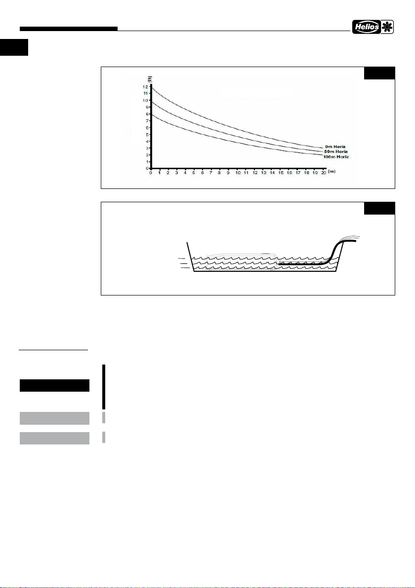
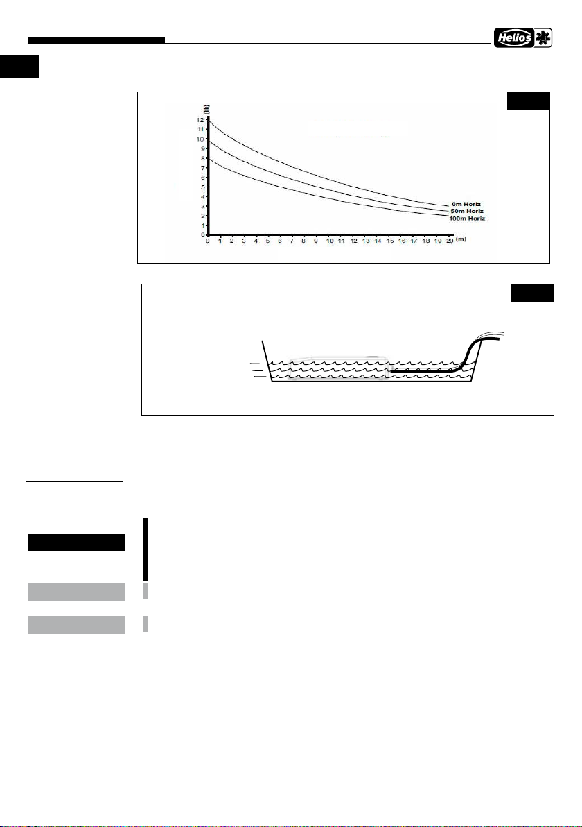
Bestimmung der Förderhöhe
2.2 Funktionsbeschreibung
Die Kondensatpumpe KWL-KP-I verfügt über einen internen Sensor, der die Pumpe
automatisch startet, sobald der Wasserspiegel über 5 mm steigt. Der interne Sensor
stoppt die Kondensatpumpe KWL-KP-I sobald der Wasserpegel auf ca. 5 mm fällt. Ein
Alarmrelais spricht an, wenn der Wasserpegel über ca. 25 mm steigt. Die Pumpe läuft
solange bis der Mindest-Wasserpegel erreicht ist. Der Alarm wird dann zurückgesetzt.
3.1 Montage
Vor allen Wartungs- und Installationsarbeiten oder vor Önen des Klemmenkastens
ist das Gerät allpolig vom Netz zu trennen! Der elektrische Anschluss darf nur von
einer autorisierten Elektrofachkraft entsprechend der Anschlusspläne ausgeführt
werden. Der Elektroanschluss muss bis zur finalen Montage allpolig vom Netz ge-
trennt sein!
Die Kondensatwanne gründlich ausspülen, um alle metallischen Partikel und Fremdkörper
zu entfernen, bevor die Kondensatpumpe KWL-KP-I in die Kondensatwanne gelegt wird.
Niemals die Kondensatpumpe KWL-KP-I „trocken“, ohne Wasser, betreiben.
1. Die Kondensatpumpe KWL-KP-I flach und horizontal auf den Boden der Kondensat-
wanne legen, neben den Ablaufstutzen.
2. Zur weiteren Geräuschreduktion sicherstellen, dass die Kondensatpumpe KWL-KP-I
keine Seitenwände der Kondensatwanne berührt. Dabei die Schlauch- bzw. Kabel-
durchführung nutzen. Die Kondensatpumpe KWL-KP-I ist mit Anti-Vibrationsfüßen
ausgestattet, um den damit verbundenen Geräuschpegel zu minimieren.
3. Den Kondensatschlauch an die Kondensatpumpe anschließen und auf die Innenseite
der Gehäusedurchführung stecken.
4. Auf der Außenseite der Geräterückwand wird der Kondensatschlauch (bauseits bereit-
gestellt) ebenfalls auf das Anschlussstück der Gerätedurchführung aufgesteckt.
Flussrate l/h
Pumpleistung
Vertikale Förderhöhe (m)
Abb.1
Abb.2
Alarm aktiviert
Pumpe arbeitet
Pumpe arbeitet nicht
KAPITEL 3
INSTALLATION
m
GEFAHR
ACHTUNG
ACHTUNG

DEDE
Kondensatpumpe – KWL-KP-I
Montage- und Betriebsvorschrift
4
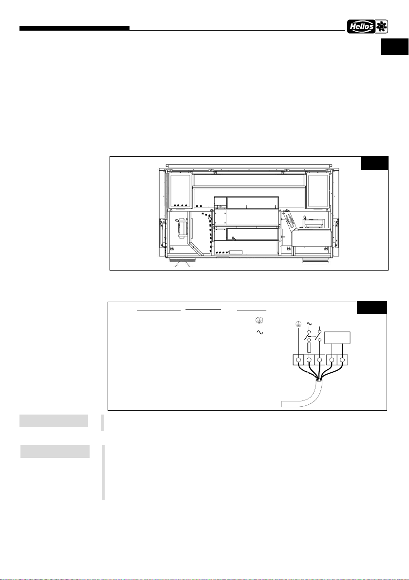
3.2 Elektrische Installation
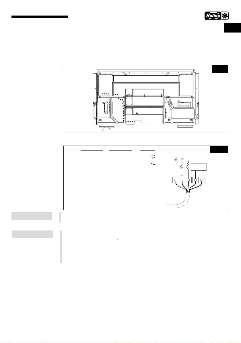
3.2.1Kondensatpumpe KWL-KP-I anschließen (KWL-Yoga Style)
1. Das Netzkabel ➊im Gerät verlegen und durch die Gummitülle nach außen zum Klem-
menkasten ➋führen (s. Abb.3).
3.2.2Stromseitiger Anschluss
Für den Anschluss an KWL-Yoga Style den Schaltplan in der Montage- und Betriebs-
vorschrift KWL-Yoga Style, 20 236, beachten.
Die Spannungsversorgung der KWL-KP-I wird an die Klemme 2A und N des Klemmen-
blocks der KWL-Yoga Style angeschlossen und die im Lieferumfang der KWL-KP-I
enthaltene Sicherung (flinke Sicherung (250 V 200 mA) primärseitig einsetzen) muss in
Reihe dazwischen verdrahtet werden.
Der Alarmkontakt der KWL-KP-I wird verbunden mit den Klemmen 39+38 der KWL-
Yoga Style Hauptplatine (s. Schaltplan in der Montage- und Betriebsvorschrift KWL-
Yoga Style).
➋
➊
Abb.3
Drahtfarbe Verbindung Symbol
1 GRÜN/ GELB ERDUNG E
2 SCHWARZ SPANNUNG L
3 WEISS NEUTRAL N
4 VIOLETT Alarmkontakt
5 VIOLETT Alarmkontakt
STROMVERSORGUNG
EL N
KONTROLL
SCHALTKREIS
1A
FUSE
1 2 3 4 5
D
Abb.4
HINWEIS
HINWEIS

DEDE
Kondensatpumpe – KWL-KP-I
Montage- und Betriebsvorschrift
5
4.1 Service und Wartung
Der Kondensatschlauch muss alle 6 Monate auf Schmutz und Schäden überprüft werden.
4.2 Test der Pumpenfunktion
1. Die Kondensatwanne mit sauberem Leitungswasser füllen bis der Wasserpegel ca.
die halbe Höhe des Gehäuses der Kondensatpumpe KWL-KP-I erreicht hat (Abb.2.
„Pumpe arbeitet“). Die Kondensatpumpe KWL-KP-I sollte anfangen zu pumpen. Die
Kondensatpumpe KWL-KP-I kann anfangs laut sein bis die gesamte Luft aus dem
System abgeführt ist.
2. Die Kondensatwanne mit weiterem Wasser füllen bis der Wasserpegel von „Alarm
aktiviert“ erreicht ist (Abb.2.). Die Alarmkontakte önen sich. Die Kondensatpumpe
KWL-KP-I leert die Kondensatwanne. Sobald der Wasserpegel in die Nähe des Ge-
häusebodens der Kondensatpumpe KWL-KP-I kommt, sollte die Pumpe stoppen und
das Alarmrelais zurückgesetzt werden (Abb.2. „Pumpe arbeitet nicht“).
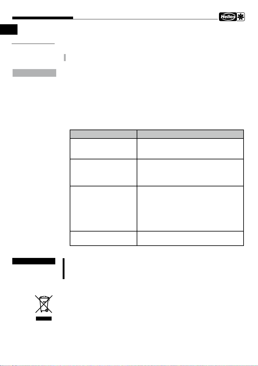
4.3 Problembehebung
Fehler Behebung
Pumpe arbeitet nicht Sicherung/elektrische Verbindungen prüfen. Der
Wasserpegel muss hoch genug sein, damit die
Kondensatpumpe anfängt zu arbeiten
Pumpe macht laute Ge-
räusche
Das Netzkabel der Kondensatpumpe und der
Kondensatschlauch dürfen nicht gegen die Kon-
densatwannenseite schlagen. Kondensatwanne
auf Fremdkörper überprüfen.
Pumpe läuft ohne Wasser
weiter
Überempfindlichkeit des Wassersensors durch
Dreck/Reinigungschemikalien:
Kondensatpumpe vom Netz trennen. Sensor-
gehäuse ca. 30 s lang mit sauberem Wasser
spülen. Ggf. den Spülvorgang mit Brennspiritus
wiederholen und mit Wasser nachspülen.
Pumpe pumpt Luft Position der Kondensatpumpe prüfen (flach und
horizontal). Kondensatschlauch auf Anzeichen
von Undichtigkeiten/Schäden prüfen.
4.4 Stilllegen und Entsorgen
mLebensgefahr durch elektrischen Stromschlag!
Bei der Demontage werden spannungsführende Teile freigelegt, die bei Berüh-
rung zu einem elektrischen Schlag führen. Vor der Demontage Ventilator allpolig
vom Netz trennen und gegen Wiedereinschalten sichern!
Bauteile und Komponenten des Ventilators, die ihre Lebensdauer erreicht haben, z.B.
durch Verschleiß, Korrosion, mechanische Belastung, Ermüdung und / oder durch
andere, nicht unmittelbar erkennbare Einwirkungen, sind nach erfolgter Demontage
entsprechend den nationalen und internationalen Gesetzen und Vorschriften fach- und
sachgerecht zu entsorgen. Das Gleiche gilt auch für im Einsatz befindliche Hilfsstoe wie
Öle und Fette oder sonstige Stoe. Die bewusste oder unbewusste Weiterverwendung
verbrauchter Bauteile wie z.B. Laufräder, Wälzlager, Motoren, etc. kann zu einer Ge-
fährdung von Personen, der Umwelt sowie von Maschinen und Anlagen führen. Die ent-
sprechenden, vor Ort geltenden Betreibervorschriften sind zu beachten und anzuwenden.
KAPITEL 4
SERVICE UND
WARTUNG
ACHTUNG
mGEFAHR
nm

DEDE
Kondensatpumpe – KWL-KP-I
Montage- und Betriebsvorschrift
6

ENEN
Condensate pump KWL-KP-I
Installation and Operating Instructions
1
1.1 Important information
In order to ensure correct operation and for your own safety, please read and observe
the following instructions carefully before proceeding. Relevant national standards, safety
regulations and provisions (e.g. DIN EN VDE 0100) as well as the technical connection
conditions of the energy supply company must be observed and applied.
Keep the operating instructions close to the unit for easy reference. The document must
be issued to the operator (tenant/owner) after the final assembly.
1.2 Warning and safety instructions
The adjacent symbol is a safety-relevant prominent warning label. All safety re-
gulations and/or symbols must be absolutely adhered to, so that any dangerous
situation is avoided.
mDANGER
Indicates dangers which will directly result in death or serious injury if the safety instruc-
tion is not followed.
mWARNING
Indicates dangers which will result in death or serious injury if the safety instruction is not
followed.
mCAUTION
Indicates dangers which can result in injuries if the safety instruction is not followed.
ATTENTION
Indicates dangers which can result in material damage if the safety instruction is not followed.
- This pump is provided with a grounding conductor.
- To reduce the risk of electric shock, be certain that it is connected only to a properly
grounded, grounding type receptacle.
- During electrical installation, make sure this condensate pump is connected to a circuit
having switch with contact separation in all poles that provide full disconnection from the
power supply in the event of category III overvoltage.
- During electrical installation, a fuse non-time delay (rated 250 V 200 mA), shall be fitted into
the line, supply side, see electrical installation section.
- The power cord is not replaceable. If the power cord is damaged the entire pump must
be replaced.
- Children should be supervised to ensure that they are not left unattended in the area where
the pump is in use.
- Children or persons with reduced physical, sensory or mental capabilities which limits their
ability to use the appliance should have a responsible person to instruct them in its use.
1.3 Warranty claims – Exclusion of liability
Our warranty shall not apply if the following instructions are not observed. The same
applies for liability claims against the manufacturer. The use of accessories which are
not recommended or oered by Helios is not permitted. Any damage that may occur is
not liable for warranty.
1.4 Regulations – Guidelines
If the product is installed correctly and used to its intended purpose, it conforms to all
applicable regulations and EC guidelines at its date of manufacture.
1.5 Receipt
Please check delivery immediately on receipt for accuracy and damage. If damaged,
please notify the carrier immediately. In case of delayed notification, any possible claim
may be void.
CHAPTER 1
GENERAL
INFORMATION
m
mDANGER
mWARNING
mCAUTION
ATTENTION

ENEN
Condensate pump KWL-KP-I
Installation and Operating Instructions
2
1.6 Storage
When storing for a prolonged time the following steps are to be taken to avoid damaging
influences:
Protection by dry, air- dustproof packing (plastic bags with drying agent and moisture
indicators). The storage place must be waterproof, vibration-free and free of excessive
temperature variations (0 to +40 °C). Damages due to improper transportation, storage
or commissioning are verifiable and not liable for warranty.
1.7 Intended use
Condensate that accumulates in the ventilation unit due to heat recovery can be drained with
the condensate pump KWL-KP-I.
The condensate pump KWL-KP-I can be connected to KWL ventilation.
In order to be able to use the pump in KWL units, a suciently large condensate tray is
required. (See switch-on and switch-o heights in Fig.4)
KWL-KP-I is a completely sealed submersible condensate pump for unit-integrated use
in the condensate tray.
The condensate pump KWL-KP-I may only be used indoors and with clean water up
to max. + 25°C. It is not intended for use under water.
Any use other than the intended use is prohibited!
2.1 Technical data
KWL-KP-I
Flow rate max. 12 l/h
Suction head max. 1 m
Discharge head max. 20 m
Ambient temperature 0-40 °C
Water temperature max. + 25 °C
Material ABS piston pump
Voltage 230 V
Frequency 50/60 Hz
Power supply 16 W
Protection category IP68
Alarm relay 5 A, 30 VDC, 250 VAC, NC
Dimensions 43 x 34 x 160 mm (B x H x L)
Cable length 2 m
Weight 470 g
The condensate pump KWL-KP-I requires a condensate hose (provided by custo-
mer) with an internal diameter of 5 - 6 mm.
NOTE
NOTE
ATTENTION
CHAPTER 2
TECHNICAL DATA
NOTE
ENEN
Condensate pump KWL-KP-I
Installation and Operating Instructions
3
Determination of the discharge head
2.2 Functional description
The internal condensate pump KWL-KP-I has an internal sensor that automatically starts
the pump as soon as the water level rises above 5 mm. The internal sensor stops the
internal condensate pump KWL-KP-I as soon as the water level drops to approx. 5 mm.
An alarm relay will respond when the water level rises above approx. 25 mm. The pump
will run until the minimum water level is reached. The alarm is then reset.
3.1 Installation
The unit must be fully isolated from the mains power supply before all mainte-
nance and installation work and opening the terminal compartment! The electrical
connections must be carried out in accordance with the wiring diagrams and must
only be carried out by qualified electricians. The electrical connection must be fully
isolated until the final assembly!
Thoroughly rinse the condensate tray to remove all metallic particles and foreign objects
before placing the condensate pump KWL-KP-I in the condensate tray.
The condensate pump KWL-KP-I should never be operated “dry” without water.
1. Place the condensate pump KWL-KP-I flat and horizontally on the bottom of the
condensate tray, next to the drain connector.
2. For further noise reduction, ensure that the condensate pump KWL-KP-I is not
touching any condensate tray side walls. Use the hose or cable opening for this. The
condensate pump KWL-KP-I is equipped with anti-vibration feet to minimise the
associated noise level.
3. Connect the condensate hose to the condensate pump and plug it onto the inside of
the casing opening.
4. Also plug the condensate hose (provided by customer) onto the unit opening connec-
tor on the outside of the rear wall of the unit.
Flow rate l/h
Capacity
Vertical lift (m)
Fig.1
Fig.2
Alarm On
Pump On
Pump O
CHAPTER 3
INSTALLATION
m
DANGER
ATTENTION
ATTENTION
ENEN
Condensate pump KWL-KP-I
Installation and Operating Instructions
4
3.2 Electrical connection
3.2.1Connect the condensate pump KWL-KP-I (KWL-Yoga Style)
1. Place the power cable ➊in the unit and lead it through the rubber grommet outwards
to the terminal box ➋(see Fig.3).
3.2.2Power supply connection
Refer to the wiring diagram in the KWL-Yoga Style installation and operating instruc-
tions, 20 236, for the connection to KWL-Yoga Style.
The KWL-KP-I power supply is connected to terminal 2A and N of the KWL-Yoga
Style terminal block and the fuse included in the scope of delivery of the KWL-KP-I
(use fast-acting fuse (250 V 200 mA) on the primary side) must be wired in series in
between.
The KWL-KP-I alarm contact is connected to terminals 39+38 of the KWL-Yoga Style
main board (see wiring diagram in the KWL-Yoga Style installation and operating ins-
tructions).
➋
➊
Fig.3
Drahtfarbe Verbindung Symbol
1 GRÜN/ GELB ERDUNG E
2 SCHWARZ SPANNUNG L
3 WEISS NEUTRAL N
4 VIOLETT Alarmkontakt
5 VIOLETT Alarmkontakt
STROMVERSORGUNG
EL N
KONTROLL
SCHALTKREIS
1A
FUSE
1 2 3 4 5
D
Fig.4
Wire colour
1 GREEN/YELLOW
2 BLACK
3 WHITE
4 VIOLET
5 VIOLET
Connection
EARTH
LIVE
NEUTRAL
Alarm contact
Alarm contact
Symbol Power supply
Control
circuit
NOTE
NOTE
ENEN
Condensate pump KWL-KP-I
Installation and Operating Instructions
5
4.1 Service and maintenance
The condensate hoses must be checked for dirt and damage every 6 months.
4.2 Testing
1. Fill the drain pan with clean tap water until the water level is approximately half way
up the condensate pump body (Fig.2. “Pump On“). The condensate pump KWL-KP-I
should start to pump. The condensate pump KWL-KP-I may be noisy initially until any
air has been purged from the system.
2. Continue to fill the drain pan until the water level reaches the “Alarm On“ level (Fig.2.).
The alarm contacts should open. Allow the condensate pump KWL-KP-I to empty
the drain pan. The condensate pump KWL-KP-I should stop and the alarm relay
reset when the water level gets close to the bottom of the condensate pump body
(Fig.2. “Pump O“).
4.3 Trouble shooting
Error Troubleshooting
Pump does not run Check fuse and electrical supply connections.
Check water level is high enough to start the
pump.
Pump is noisy Check that the condensate pump mains cable
and outlet tube are not vibrating against the si-
des of the drain pan and that there is no debris
in the bottom of the drain pan.
Pump continues to run with
no water
The water sensor can become over sensitive if
contaminated by dirt or certain cleaning chemi-
cals. If this occurs, disconnect the condensate
pump from the mains supply and flush the sen-
sor housing with clean tap water for around 30
s. If the problem persists, flush with methylated
spirit and then rinse with water.
Pump is pumping air Check that the condensate pump is flat and le-
vel. Check that the outlet tube is not syphoning.
4.4 Standstill and disposal
m Danger to life due to electric shock!
When dismantling, live parts can be exposed, which can result in electric shock
if touched. Before dismantling, isolate the unit from the mains power supply and
protect against being switching on again!
Parts and components of the fan, whose service life has expired, e.g. due to wear and
tear, corrosion, mechanical load, fatigue and/or other eects that cannot be directly
discerned, must be disposed of expertly and properly after disassembly in accordance
with the national and international laws and regulations. The same also applies to auxi-
liary materials in use. Such as oils and greases or other substances. The intended and
unintended further use of worn parts, e.g. impellers, rolling bearings, filters, etc. can
result in danger to persons, the environment as well as machines and systems. The
corresponding operator guidelines applicable on-site must be observed and used.
CHAPTER 4
SERVICE AND
MAINTENANCE
ATTENTION
mDANGER
nm

ENEN
Condensate pump KWL-KP-I
Installation and Operating Instructions
6

FRFR
Pompe à condensat KWL-KP-I
Notice de montage et d’utilisation
1.1 Informations importantes
Il est important de bien lire et suivre l’ensemble des consignes suivantes pour le bon
fonctionnement de l’appareil et pour la sécurité des utilisateurs. Les normes nationales,
les conditions de sécurité et les réglementations (la norme NF C15-100 par ex.) ainsi
que les conditions techniques de raccordement de la société d’approvisionnement en
électricité sont à respecter et à appliquer impérativement.
Garder la notice à proximité de l’appareil. Après le montage final, le document doit être
remis à l’utilisateur (locataire / propriétaire).
1.2 Précautions et consignes de sécurité
Les symboles ci-contre indiquent une consigne de sécurité. Toutes les consignes
de sécurité ainsi que les symboles doivent être impérativement respectés, afin
d’éviter tout danger.
mDANGER
Dangers pouvant entrainer la mort ou des blessures graves si les mesures ne sont pas res-
pectées.
mAVERTISSEMENT
Dangers pouvant entrainer la mort ou des blessures graves si les mesures ne sont pas res-
pectées.
mATTENTION
Dangers pouvant entrainer des blessures graves si les mesures ne sont pas respectées.
POINT IMPORTANT
Dangers pouvant entrainer des dommages matériels si les mesures ne sont pas respectées.
- Cette pompe est équipée d’un conducteur de mise à la terre.
- Afin de réduire le risque d’électrocution, il convient de s’assurer que l’appareil est exclusi-
vement branché sur une prise de terre correctement mise à la terre.
- Pendant l’installation électrique, s’assurer que la pompe est connectée à un circuit équipé
d’un disjoncteur omnipolaire afin de garantir une déconnexion totale de l’alimentation
électrique en cas de surtension de catégorie III.
- Pendant l’installation électrique, un fusible à action rapide (250V 200mA) doit être inséré
dans le câble d’alimentation du côté primaire, voir la section sur l’installation électrique.
- Le câble d’alimentation n’est pas remplaçable. Si le câble d’alimentation est endommagé,
la pompe doit être remplacée dans son intégralité.
- Les enfants doivent être surveillés afin de s’assurer qu’ils ne se trouvent pas sans surveil-
lance dans la zone de la pompe utilisée.
- Les enfants ou les personnes dont les capacités physiques, sensorielles ou mentales sont
réduites et les limitent dans l’utilisation de l’appareil doivent être accompagnés par une
personne responsable qui leur fournira des instructions relatives à l’utilisation de l’appareil.
1.3 Demandes de garantie – Réserves du constructeur
Si les consignes indiquées dans cette notice ne sont pas correctement respectées, la
garantie s’annule. Il en est de même pour toute implication de responsabilité du fabricant.
L’utilisation d’accessoires non conseillés ou proposés par Helios n’est pas permise. Les
dégâts causés par cette mauvaise utilisation ne sont pas couverts par la garantie.
1.4 Règlementations – Normes
Sous réserve d’une installation et d’une utilisation appropriées, ce produit est conforme
à la réglementation et aux directives CE en vigueur le jour de sa fabrication.
1.5 Réception de la marchandise
Dès réception, vérifier l’état et la conformité du matériel commandé. En cas de dégâts,
les signaler immédiatement en mentionnant le nom du transporteur. Attention, le non-res-
pect de ces procédures peut entraîner le rejet de la réclamation.
CHAPITRE 1
GÉNÉRALITÉS
REMARQUES
m
mDANGER
mAVERTISSEMENT
mATTENTION
POINT IMPORTANT
1
FRFR
Pompe à condensat KWL-KP-I
Notice de montage et d’utilisation
1.6 Stockage
Pour un stockage de longue durée et pour éviter toute détérioration préjudiciable, il
convient de se conformer aux instructions suivantes:
Protéger avec un emballage sec, étanche à l’air et à la poussière (sac en matière syn-
thétique contenant des sachets déshydrateurs et un indicateur d’humidité). Stocker le
matériel dans un endroit abrité de l’eau, exempt de vibrations et de variations de tem-
pératures excessives (0 à +40°C). Les dommages dus à de mauvaises conditions de
transport ou de stockage ou à une utilisation anormale sont décelables et ne sont pas
couverts par la garantie.
1.7 Utilisation conforme
La pompe à condensat
KWL-KP-I
permet d’évacuer facilement les condensats du conduit
des condensats et de les amener à une certaine hauteur.
La pompe à condensat KWL-KP-I peut être raccordée aux centrales KWL.
Pour pouvoir utiliser la pompe dans les appareils KWL, il faut disposer d’un bac de
condensats susamment grand. (voir hauteurs d’enclenchement et de déclenchement
dans Fig.2)
KWL-KP-I est une pompe à condensat submersible entièrement étanche, pour une
utilisation intégrée à l’appareil dans le bac de condensats.
La pompe à condensat KWL-KP-I ne peut être utilisée qu’à l’intérieur et avec de
l’eau propre jusqu’à + 25°C maximum. Elle n’est pas destinée à être utilisée sous
l’eau.
Tout usage inapproprié est interdit!
2.1 Données techniques
KWL-KP-I
Débit de refoulement max. 12l/h
Hauteur d’aspiration max. 1 m
Hauteur de refoulement max. 20m
Température de fonctionnement 0 – 40°C
Température max. de l’eau + 25°C
Matériau pompe à piston en ABS
Tension 230 V
Fréquence 50/60Hz
Alimentation électrique 16 W
Indice de protection IP68
Relais d’alarme 5A, 30VCC, 250VCA, NC
Dimensions pompe 43 x 34 x 160mm (lxHxL)
Longueur de câble 2m
Poids 470g
La pompe à condensat KWL-KP-I nécessite un conduit des condensats (à fournir
par le client) d’un diamètre intérieur de 5 - 6mm.
REMARQUEREMARQUE
REMARQUE
POINT IMPORTANT
CHAPITRE 2
DONNÉES
TECHNIQUES
REMARQUE
2

FRFR
Pompe à condensat KWL-KP-I
Notice de montage et d’utilisation
Détermination de la hauteur de refoulement
2.2 Description du fonctionnement
La pompe à condensat KWL-KP-I dispose d’un capteur interne qui démarre automati-
quement la pompe dès que le niveau d’eau dépasse 5mm. Le capteur interne arrête la
pompe à condensat KWL-KP-I dès que le niveau d’eau descend à environ 5mm. Un
relais d’alarme se déclenche lorsque le niveau d’eau dépasse environ 25mm. La pompe
continue de fonctionner jusqu’à ce que le niveau d’eau minimum soit atteint. L’alarme est
alors réinitialisée.
3.1 Montage
Mettre impérativement la centrale hors tension avant tous travaux d’entretien,
d’installation ou avant l’ouverture du coret électrique! Le raccordement électrique
doit être eectué par un électricien qualifié et selon les schémas de raccordement.
L’alimentation électrique doit être maintenue hors tension jusqu’à la fin de l’instal-
lation!
Rincer soigneusement le bac de condensats afin d’éliminer toutes les particules métal-
liques et les corps étrangers avant de placer la pompe à condensat KWL-KP-I dans le
bac de condensats.
Ne jamais faire fonctionner la pompe à condensat KWL-KP-I «à sec» sans eau.
1. Poser la pompe à condensat KWL-KP-I à plat et à l’horizontale sur le fond du bac de
condensats, à côté de la sortie des condensats.
2. Pour réduire davantage le bruit, s’assurer que la pompe à condensat KWL-KP-I ne
touche aucune paroi latérale du bac de condensats. Pour cela, utiliser le tuyau d’éva-
Débit l/h
Puissance de pompe
Hauteur de refoulement verticale (m)
Fig.1
Fig.2
Alarme activée
Pompe fonctionne
Pompe ne fonctionne
pas
CHAPITRE 3
INSTALLATION
m
DANGER
POINT IMPORTANT
POINT IMPORTANT
3
FRFR
Pompe à condensat KWL-KP-I
Notice de montage et d’utilisation
cuation ou le câble d’alimentation.. La pompe à condensat KWL-KP-I est équipée de
pieds anti-vibrations afin de minimiser le niveau sonore qui résulte de son utilisation.
3. Raccorder le conduit des condensats à la pompe à condensat et insérer le ensuite à
l’intérieur du boîtier.
4. Passez également le tuyau de condensat (fourni par le client) via le pré-trou de l’unité
qui se situe sur la paroi arrière de l’unité.
3.2 Raccordement électrique
3.2.1Raccorder la pompe à condensat KWL-KP-I (KWL-Yoga Style)
1. Poser le câble d’alimentation ➊dans l’appareil et le faire passer par le passe-fil en
caoutchouc vers l’extérieur jusqu’à la boîte à bornes ➋(voir Fig.3).
3.2.2Raccordement côté courant
Pour le raccordement au KWL-Yoga Style, se référer au schéma électrique figurant dans
les instructions de montage et de fonctionnement KWL-Yoga Style, 20 236.
L’alimentation électrique du KWL-KP-I est raccordée aux bornes 2A et N du bornier
du KWL-Yoga Style et le fusible fourni avec le KWL-KP-I (utiliser un fusible rapide
(250 V 200 mA) côté primaire) doit être câblé en série entre les deux.
Le contact d’alarme du KWL-KP-I est relié aux bornes 39+38 de la carte principale
KWL-Yoga Style (voir le schéma de câblage dans les instructions de montage et de
fonctionnement du KWL-Yoga Style).
➋
➊
Fig.3
Drahtfarbe Verbindung Symbol
1 GRÜN/ GELB ERDUNG E
2 SCHWARZ SPANNUNG L
3 WEISS NEUTRAL N
4 VIOLETT Alarmkontakt
5 VIOLETT Alarmkontakt
STROMVERSORGUNG
EL N
KONTROLL
SCHALTKREIS
1A
FUSE
1 2 3 4 5
D
Fig.4
Couleur du fil
1 VERT/JAUNE
2 NOIR
3 BLANC
4 VIOLET
5 VIOLET
Connexion
TERRE
TENSION
NEUTRE
Contact d‘alarme
Contact d‘alarme
Symbole Alimentation électrique
Circuit de
contrôle
REMARQUE
REMARQUE
4

FRFR
Pompe à condensat KWL-KP-I
Notice de montage et d’utilisation
4.1 Entretien et maintenance
L’absence de saleté et de dommages au niveau de la pompe à condensat doit être
vérifiée tous les 6mois.
4.2 Test du fonctionnement de la pompe
1. Remplir le bac de condensats avec de l’eau propre du robinet jusqu’à ce que le niveau
d’eau atteigne environ la moitié de la hauteur du boîtier de la pompe à condensat
KWL-KP-I (Fig.2. «La pompe fonctionne»). La pompe à condensat KWL-KP-I doit
commencer à pomper. La pompe à condensat KWL-KP-I peut être bruyante au début
jusqu’à ce que tout l’air soit évacué du système.
2. Remplir le bac de condensats avec plus d’eau jusqu’à ce que le niveau d’eau de
«Alarme activée» soit atteint (Fig.2.). Les contacts d’alarme s’ouvrent. La pompe à
condensat KWL-KP-I vide le bac des condensats. Dès que le niveau d’eau s’approche
du fond du boîtier de la pompe à condensat KWL-KP-I, la pompe doit s’arrêter et le
relais d’alarme doit être réinitialisé (Fig.2. «La pompe ne fonctionne pas»).
4.3 Résolution des problèmes
Problème Solution
La pompe ne fonctionne pas Vérifier les fusibles/les raccordements élec-
triques. Le niveau d’eau doit être susamment
élevé pour que la pompe à condensat com-
mence à fonctionner.
Le niveau sonore de la
pompe est élevé
Le câble d’alimentation de la pompe à conden-
sat et le conduit des condensats ne doivent pas
heurter le côté du bac de condensats. Vérifier
que le bac de condensats ne contient pas de
corps étrangers.
La pompe continue de fonc-
tionner sans eau
Le capteur d’eau peut devenir hypersensible
avec la présence de saleté ou de produits
chimiques Déconnecter la pompe à condensat
du réseau. Rincer le boîtier du capteur pendant
env. 30secondes avec de l’eau propre. Le cas
échéant, répéter l’opération de rinçage avec de
l’alcool à brûler et rincer à nouveau à l’eau.
La pompe pompe de l’air Vérifier la position de la pompe à condensat (à
plat et à l’horizontale). Vérifier que le conduit
des condensats ne présente pas de signes de
fuite/d’endommagement.
CHAPITRE 4
ENTRETIEN ET
MAINTENANCE
POINT IMPORTANT
5
FRFR
Pompe à condensat KWL-KP-I
Notice de montage et d’utilisation
6
4.4 Démontage et recyclage
m Risque de mort par électrocution !
Lors du démontage, les parties sous tension peuvent déclencher un choc élec-
trique. Avant le démontage, mettre le ventilateur hors tension et éviter tout redé-
marrage intempestif !
Les pièces, composants et matériel démonté arrivés en fin de vie (usure, corrosion, dégra-
dation, etc.), sans conséquences nuisibles immédiates, sont à recycler selon les normes
et règlementations nationales et internationales. Idem pour les produits consommables
(huile, graisse, etc.).
La réutilisation consciente ou inconsciente de matériel usé (hélices, turbines, courroies,
etc.) peut représenter un danger pour les personnes et pour l’environnement, tout comme
pour les machines et les installations. Il est important de connaître et respecter les normes
locales.
mDANGER
nm

Service und Information
DHELIOS Ventilatoren GmbH + Co KG · Lupfenstraße 8 · 78056 VS-Schwenningen FHELIOS Ventilateurs · Le Carré des Aviateurs · 157 avenue Charles Floquet · 93155 Le Blanc Mesnil Cedex
CH HELIOS Ventilatoren AG · Tannstrasse 4· 8112 Otelfingen GB HELIOS Ventilation Systems Ltd. · 5 Crown Gate · Wyncolls Road · Severalls Industrial Park ·
AHELIOS Ventilatoren · Postfach 854 · Siemensstraße 15 · 6023 Innsbruck Colchester · Essex · CO4 9HZ
www.heliosventilatoren.de
Als Referenz am Gerät gribereit aufbewahren! Druckschrift-Nr.
Please keep this manual for reference with the unit! Print-No.
Conservez cette notice à proximité de l’appareil! N° Réf. 20 411-001/-/V01/0423
Table of contents
Languages:
Other Helios Water Pump manuals


Popular Water Pump manuals by other brands


Grundfos
Grundfos DMI 208 Installation and operating instructions

Sandpiper
Sandpiper MSA2 Service manual

Franklin Electric
Franklin Electric Little Giant 1-EA-42 manual

Graco
Graco President E Series Instructions-parts list

TorcUP
TorcUP EMINI Operation and maintenance manual

Flotec
Flotec FP6005 owner's manual