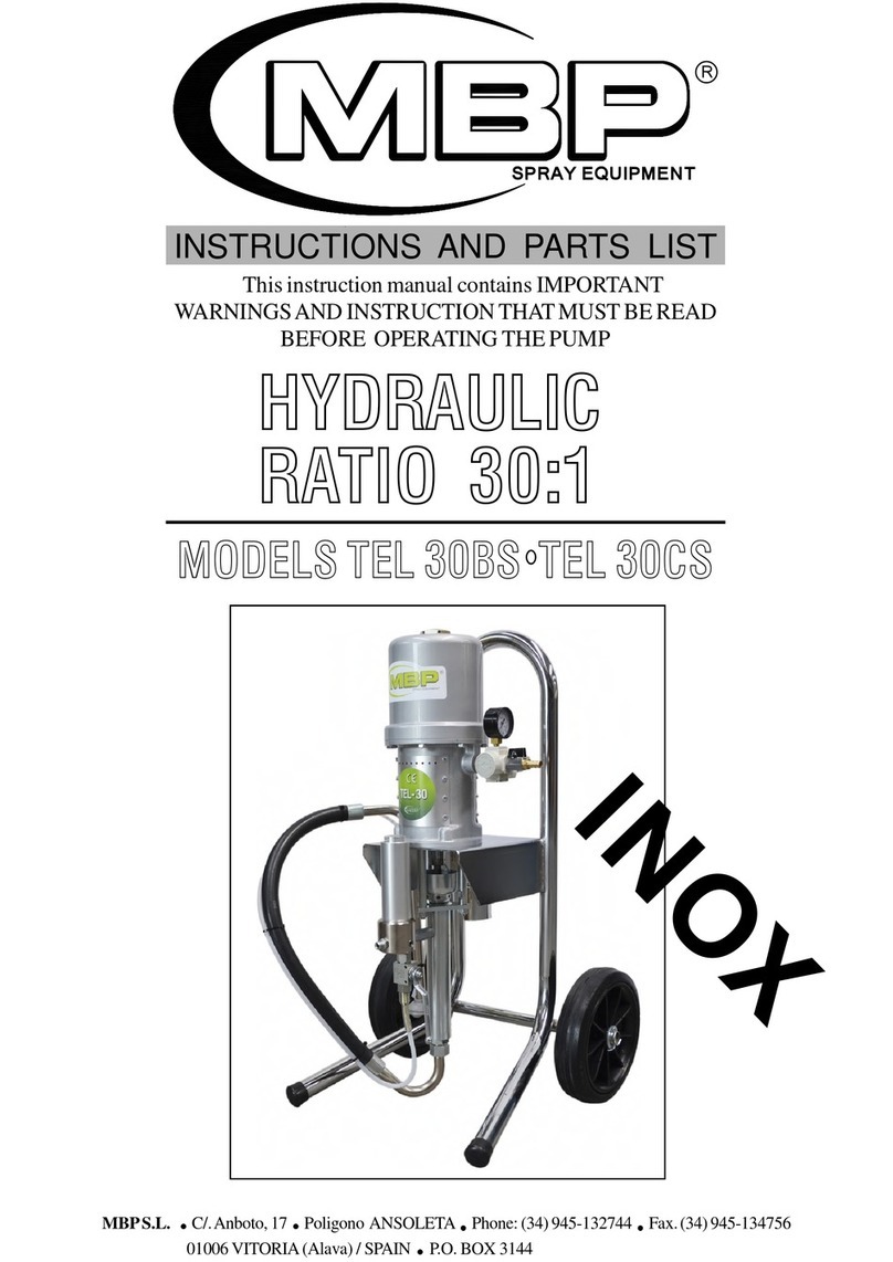
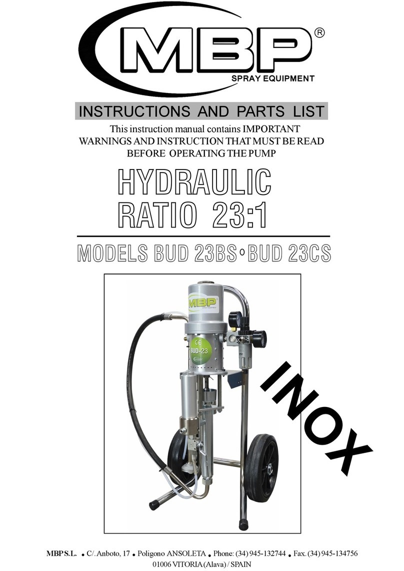
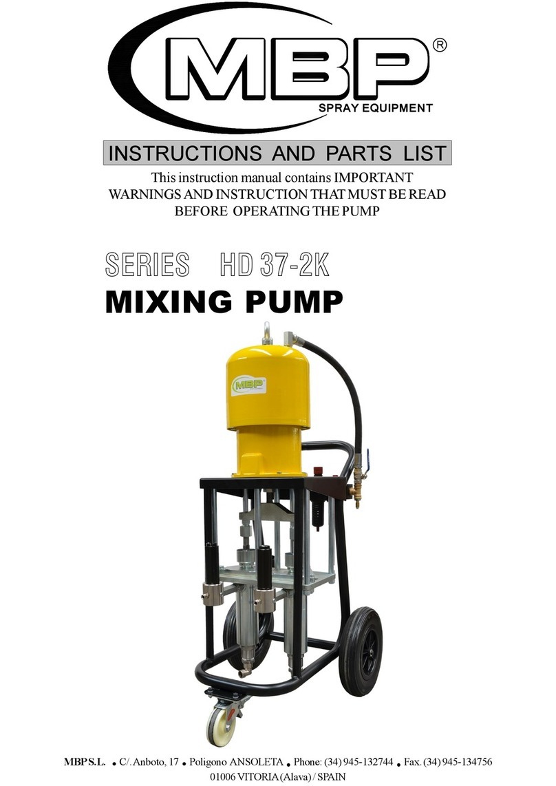
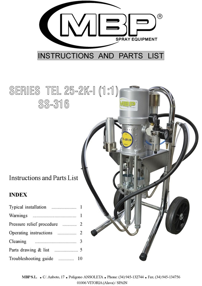
mbp TEL 16-2K Series Datasheet

INSTRUCTIONS AND PARTS LIST
SPRAY EQUIPMENT
MBPS.L. C/.Anboto, 17 Poligono ANSOLETA Phone: (34) 945-132744 Fax.
(34) 945-134756
01006 VITORIA (Alava) / SPAIN P.O. BOX 3144
INDEX
Typical installation ........................ 1
Warnings ....................................... 1
Pressure relief procedure ............... 2
Operating instructions ................... 2
Cleaning ...................................... 3
Parts drawing & list ....................... 5
Troubleshooting guide ................ 12
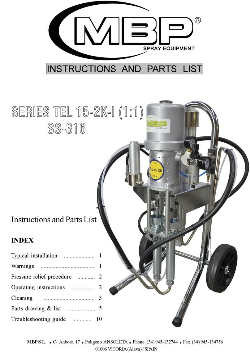
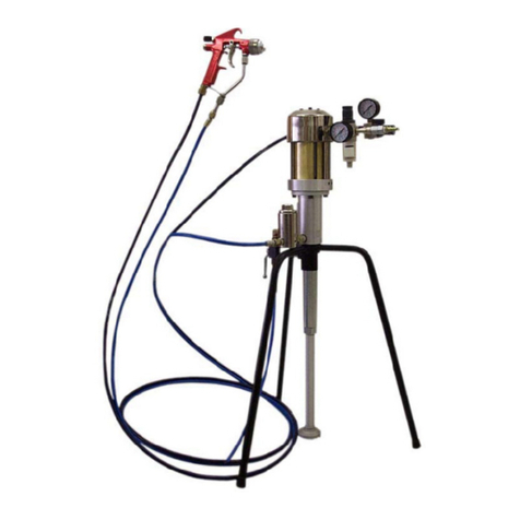
SERIES TEL 16-2K
(2:1)
MIXING PUMP
Instructions and Parts List

BASE
DISOLVENTE
DE LIMPIEZA
CATALIZADOR
BASE
RESINA
1
WARNING
ATTENTION!! Read and understand all instructions carefully before operating equipment.
INJECTION HAZARD
This equipment generates very high fluid pressure. Spray from the gun, leaks or ruptured components
can inject fluid through your skin and into your body and cause extremely serious bodily injury.
The spray gun should never be handled carelessly, nor spray directed toward any part of the body.
Never put hand or fingers over the spray tip.
Be sure equipment safety devices are operating properly before each use.
If any fluid appears to penetrate your skin, get emergency medical care at once. Do not treat as a
simple cut. Tell the doctor exactly what fluid was injected.
TYPICAL INSTALLATION

2
1.-
2.-
3.-
4.-
5.-
6.-
7.-
8.-
Engage the gun safety latch.
Turn off the air to the pump.
Close the air inlet valve.
Disengage the gun safety latch.
Hold a metal part of the gun firmily to the side of a grounded metal pail, and trigger the
gun safety latch.
Engage the gun safety latch.
Open the drain valves (fig.1 and fig.3), having a grounded metal container ready to catch
the drainage.
Leave the drain valves open until you are ready to spray again.
PRESSURE RELIEF PROCEDURE
OPERATING INSTRUCTIONS
Follow all instructions above, be sure that fittings at pump outlet and at gun are tight. Use two wrench to
tighten the maing fitting.
Fill the packing nut with oil to help prolong the packing life.
• Turn on the air to the pump (fig.1), but the position of this valve must to be ‘’close air’’.
• Check that the A, B and C valves are in position ‘’1’’ before open the air valve.
The pump must be connected to ground with a ground wire which is supplied with the
pump (4 mm2of section and a clamp).
SPRAY GUN: Obtain grounding through connection to a properly grounded fluid
hose and pump.
OBJECT BEING SPRAYED: Use ground wire and clamp.
AIR COMPRESOR: Follow air compressor manufacturer’s recommendations.
Use ONLY METAL PAILS, which are conductive. Do not place the pail on a non-
conductive surface, such as paper or cardboard, which interrupts the grounding
continuity.
1.-
2.-
3.-
4.-
5.-
FIRE HAZARD
Static electricity is created by the high velocity flow of fluid through the pump and hose. If every
part of spray equipment is not properly grounded, sparking may occur, and the system may become
hazardous. Check the entire system for positive grounding.
GROUNDING
Before starting to work the pump must be connected to ground:

AIR INLET VALVE
‘’OPEN AIR’’
AIR INLET
‘’CLOSE AIR’’
(fig.1)
3
• Put the suction pipes into the respective containers:
‘’C’’ to base product (varnish)
‘’B’’ to catalyst
• Open the air inlet valve (fig.1) and turn on the air regulator until the pump begins to cycle. Allow the
pump to cycle slowly until all air is purged from the fluid lines. The lines are purged when the fluids
emitted from the drain valves ‘’B’’ and ‘’C’’ is flowing in a steady stream.
•Simultaneously turn off the drain valves ‘’B’’ and ‘’C’’ to the position ‘’2’’ (fig.3).
•The pump is ready.
CLEANING
• Turn off the air inlet valve (fig.1).
• Remove the spray tip and trigger gun to relieve pressure.
• Set the drain valves ‘’B’’ and ‘’C’’ in the position ‘’Working / Varnishing’’ (UP) fig.3.
• Set the air inlet valve ‘’A’’(fig.2) in position nº2. Now, the cleaning pump will start to pumpìng
solvent.
• Trigger the gun until the solvent runs clear.
When the pump stay a long time without working, is necessary to circulate solvent throuugh the three
suction pipes.

4
2 1
VALVE ‘’A’’
AIR REGULATOR ‘’X’’
(fig.2)
UP
( For working / varnishing )
DOWN
( For reclying )
B C
(fig. 3)

5
AIR MOTOR
16A.200.00
(fig. 4)
CAP
JOINT
CYLINDER
ROD
SUPPORT
YOKE
ROD
SCREW
CLIP
PISTON
STEM
JOINT
ROD
JOINT
SLEEVE
JOINT
PLATE
BASE
SCREW
SCREW
ROCKER
SPRING
ROD
CLIP
NUT
JOINT
JOINT
JOINT
RETAINER
GROUND
WIRE GROUND
1
1
1
2
1
1
1
2
2
1
2
1
1
1
1
1
2
1
6
16
2
2
2
2
4
1
2
2
1
1
1
Nº REF. DESCRIPCION Q
1
2
3
10
6
21
13
15
22 23
4
25
7
8
9
11
12
14
29
16
26
20
30
24
27
28
5
17
19
18
31
1
2
3
4
5
6
7
8
9
10
*11
*12
13
*14
15
*16
17
18
19
20
21
22
23
*24
25
26
*27
*28
29
30
31
*Included in KIT.054
A.110.02
C.JT0.01
A.210.01
A.120.04
A.220.07
A.120.08
A.221.00
C.TJ0.02
A.240.02
A.240.01
A.122.00
C.JT0.05
A.220.11
C.JT0.07
CB2.015
C.JT0.06
A.130.02
A.250.01
C.TA0.01
C.TC0.01
A.120.01
A.120.02
A.120.03
A.120.05
A.120.06
A.150.02
A.120.10
A.220.09
CAR 125
101.400.00
101.620.00

1
2
3
6
7
89
4
5
10
12
C B
13
14
15
16
17
18
19
20
11
6
UNION
SCREW
PIN
SCREW
TIE
COUPLING
SUPPORT
PUMP A
PUMP B
NUT
SUCTION
1
1
2
6
4
3
1
1
1
10
2
1
2
3
4
5
6
7
8
9
10
11
16.200.02
16.000.04
C.PA1.01
C.TA0.05
16.200.01
16.000.07
16.200.03
16B.101.00
16.400.00
C.TU1.01
D.100.00
Nº REF. DESCRIPTION Q
1
1
1
1
1
1
1
1
1
1
2
SUCTION
FILTER
FILTER
COVER
FILTER (*)
SPRING
SCREW
SUPPORT
JOINT
BODY
PLUG
16.300.00
16.313.00
D.130.00
G.100.02
G.100.05
G.100.04
C.TA9.01
G.100.03
G.100.07
16.700.01
C.TF0.01
12
B
C
13
14
15
16
17
18
19
20
Nº REF. DESCRIPTION Q
(*) FILTER 100 Mesh - Ref. G.100.05
FILTER 60 Mesh - Ref. G.100.20
FILTER 200 Mesh - Ref. G.100.21
(fig. 5)
DISPLACEMENT PUMPASSEMBLAGE FOR TEL 16-2K 2:1

7
* Included in KIT 039
NOTE: Fix parts10 and 13 with loctite 542 or similar
(wait 1 hour before start running the unit).
PIN
PACKING NUT
FEMALE GLAND
PACKING
PACKING
MALE GLAND
HOUSING
JOINT
SLEEVE
ROD
WASHER
BALL
PISTON
PIN
RETAINER
JOINT
BALL
VALVE
1
2
*3
*4
*5
*6
7
8
9
10
11
12
13
14
15
16
17
18
C.PA1.01
B.120.00
B.130.01
100.230.02
B.130.02
B.130.03
B.110.00
B.100.01
B.100.02
B.100.03
B.140.01
C.B0.202
B.150.00
B.100.05
B.170.01
B.100.06
CBO.209
B.171.00
16B.101.00
Nº REF. DESCRIPTION Q
1
1
2
6
6
2
1
1
1
1
1
1
1
1
1
1
1
1
PUMP A (PAINT)
(fig. 6)
2
1
3
6
4
5
5
4
4
4
7
10
8
9
11
4
3
13
15
18
5
6
5
12
14
4
5
5
4
4
16
17

2
1
3
6
4
5
5
4
4
4
7
10
8
9
11
13
15
17
19
20
22
5
12
14
16
18
21
13
14
13
8
PUMP B (CATALYST)
* Included in KIT 040
NOTE: Fix parts10 and 17 with loctite 542 or similar
(wait 1 hour before start running the unit).
PIN
PACKING NUT
FEMALE GLAND
PACKING
PACKING
MALE GLAND
HOUSING
JOINT
SLEEVE
ROD
WASHER
MALE GLAND
PACKING
PACKING
FEMALE GLAND
BALL
PISTON
PIN
RETAINER
JOINT
BALL
VALVE
1
2
*3
*4
*5
*6
7
8
9
10
11
*12
*13
*14
*15
16
17
18
19
20
21
22
C.PA1.01
B.120.00
16.420.01N
16.420.02PN
16.420.02TN
16.420.03N
B.110.00
B.100.01
16.400.02
16.400.01
16.411.04
16.411.01N
16.411.02PN
16.411.02TN
16.411.03N
C.B0.202
16.410.00
B.100.05
B.170.01
B.100.06
CBO.209
B.171.00
1
1
1
3
2
1
1
1
1
1
1
1
2
2
1
1
1
1
1
1
1
1
16.400.00
Nº REF. DESCRIPCION Q
(fig. 7)

8
2
6
5
11
12
13
15
11
16
7
14
10
9
4
1
3
1
11
8
9
2
3
4
2
5
7
3
C1
R2
2
9
1
2
3
4
5
6
7
8
9
10
11
12
13
14
15
16
16.120.01
16.120.02
16.121.00
16.120.03
CNB.005
CTB.032
CTB.007
CTU.105
16.100.07
16.100.05
G.100.06
CNA.116
CNC.006
CNA.057
CNA.063
16.122.00
BODY
BODY
VALVE
SEAT
GAUGE
SCREW
SCREW
NUT
MIXER
MIXER BODY
COUPLING
SWIVEL
VALVE
COUPLING
ELBOW
HANDLE
1
2
4
1
2
12
2
2
1
1
4
2
2
2
1
1
MIXER (16.120.00)
1
2
3
4
5
7
8
9
11
16.120.00
16.920.00
G.100.06
G.910.01
CTF.001
16.700.00
G.920.03
16.000.10
H.910.00
MIXER
HOSE
COUPLING
COUPLING
PLUG
HP FILTER
SPRING
TUBE
HOSE
1
3
2
1
1
1
2
2
1
Nº REF. DESCRIPTION Q
(fig. 8)
(fig. 9)

10
CTB.002
080.100.01
CNA.065
CTB.023
080.120.00
080.100.05
080.170.05
080.100.08
080.150.00
080.100.07
080.100.04
CTB.030
080.110.00
080.140.00
080.100.09
080.100.11
080.100.10
CTU.002
CTG.009
080.130.00
080.100.02
CAR.112
CAB.005
080.100.03
080.170.01
CJT.022
080.170.02
CJT.023
080.170.03
080.171.00
080.170.04
CJT.024
080.100.13
CAR.118
080.800.00
080.100.12
CJT.025
080.100.14
080.100.06
AIR MOTOR ‘‘CLEANING PUMP’’
SCREW
COVER
ELBOW
SCREW
COVER
SNUBBER
GUIDE
WASHER
AIR DISPENSER
HOUSING
SNUBBER
SCREW
MOTOR BODY
SPRING SUPPORT
SPRING BUTT END
SPRING
SUPPORT
NUT
SCREW
PLUG
BUSHING
RETAINER
RING
SEAT
PISTON
JOINT
SEAT
JOINT
WASHER
ROD
ROD
JOINT
CYLINDER
RETAINER
KEEPING BACK
MOTOR BASE
JOINT
PIPE
RING
3
1
1
2
1
1
1
1
2
1
1
4
1
2
2
2
2
2
2
1
1
2
1
1
1
1
1
1
1
1
1
2
1
1
1
1
4
2
1
Nº REF. DESCRIPTION Q
(fig. 10)
*Included in KIT.055
1
2
3
4
5
6
7
8
*9
10
11
12
13
14
15
16
17
18
19
20
21
22
*23
24
25
26
27
*28
29
30
31
32
33
34
*35
36
37
38
39

11
1
2
3
4
5
*6
*7
*8
*9
10
11
12
13
*14
*15
*16
17
18
19
20
21
22
23
24
25
26
27
28
29
30
32
33
34
1
1
1
1
1
1
4
1
1
1
1
2
1
1
4
1
1
1
1
1
1
1
1
1
1
1
1
1
4
1
1
3
1
CJT.026
CAR.111
080.200.03
080.200.01
080.210.00
080.200.04
B.131.02
B.930.04
080.200.06
CPA.109
080.200.16
080.200.07
080.200.08
080.200.12
080.200.13
080.200.15
CB0110
080.230.00
080.200.09
080.200.11
080.200.10
CB0.111
080.220.00
080.200.19
080.000.01
D.100.00
CAR.015
080.240.00
CTB.013
CNA.006
16.000.01
CTB.019
16.000.07
JOINT
RETAINER
BRIDLE
BODY
OIL TUBE
FEMALE GLAND
PACKING
PACKING
MALE GLAND
PIN
ROD
SPRING
CYLINDER
MALE GLANG
PACKING
FEMALE GLAND
BALL
PISTON VALVE
HOUSING
PIN
BALL GUIDE
BALL
INLET VALVE
JOINT
COUPLING
FLUID SUCCION
WASHER
ANTIRRETORNO
SCREW
ELBOW
SUPPORT
SCREW
COUPLING
DISPLACEMENT PUMP ‘‘CLEANING PUMP’’
Nº REF. DESCRIPTION Q
* Included in KIT 024
NOTE: Fix parts 11 and 18 with loctite 542 or similar
(wait 4 hour before start running the unit).
(fig. 11)

TROUBLESHOOTING GUIDE
Restricted line or inadequate air supply.
Insufficient air pressure, closed or clogged air
valves, etc.
Exhausted fluid supply.
Obstructed fluid hose, gun or dispensing valve.
Clogged spray tip or filters.
Clogged filters.
Throat packings nut too tight or to loose.
Exhausted fluid supply.
Obstructed fluid hose or gun.
Worn spray tip.
Held open or worn intake valve.
Held open or worn fluid piston or packings.
Exhausted fluid supply.
Check valves need adjustment.
Held open or worn intake valve.
Held open or worn fluid piston or packings.
Clear, increase air.
Open, clean.
Refill; purge all air from pumpand fluid
lines.
Clear.
Clear or replace.
Clear or replace.
Adjust.
Refil and prime.
Clear.
Replace.
Clear.
Clear or replace.
Refill and prime.
Adjust.
Clear.
Clear or replace.
PROBLEM POSSIBLE CAUSE SOLUTION
Pump. fails
to operate.
Pump operates
but output low
on down stroke.
Erratic or
accelerated
operating.
For trouble free operation is absolutelyessential that your sprayer be kept clean and free of residual paint buil-up on the
internal parts. It must be cleaned and lubricated after each use.
12

IMP 010-MARZO 2018
MBP, S.L.
e-mail:info@mbpspray.com www.mbpspray.com
WARRANTY
1.-
2.-
3.-
M.B.P., will any repairs necessary during the first 12 months after purchase of a new unit, with the exceptions shown
under 1 and 2 below, and under the conditions shown in item 3.
In no case will M.B.P.liability extend beyond repair or repalacement of the equipment. Such liability is limited to the
amount of the original purchase price paid for the unit, minus a reasonable deduction for the time the unit has been in
service. It is the responsibility of the purchaser under this warranty to ship or deliver the failed paint sprayer to the
authorized service center at the purchaser’s expence. Parts or components covered under this warranty may either
be repaired or replaced at M.B.P. option.
Equipent not covered by M.B.P. warranty. Accessories or components of equipment sold by M.B.P. that are nort
manufactured by M.B.P. are subject to the warranty, if any, of their manufacturer. M.B.P. will provide purchaser with
reasonable assistance in making such claims.
The Industry Department of The Basque Goverment, states that all electric and pneumatic airless equipment
manufacture by M.B.P. S.L., follows the ’’CE’’ standards under the number 83/392/CEE.
MODELO / MODEL TEL - 16-2K (2:1)
Este producto cumple con la siguiente directiva de la Comunidad Europea.
This Product complies with the following European Comunity Directive.
Directiva 2014/34/EU Atex sobre máquinas. (Ex II 2G c T6 X)
Machinery Directive 2014/34/EU Atex Directive. (Ex II 2G c T6 X)
APROBADO POR /
APPROVED BY AITOR ORTIZ
FECHA / DATE
MBP, S.L. figura inscrita en el Registro Industrial del País Vasco con el Nº 01/8030 y cumple los
requisitos para el desarrollo de su actividad comercial.
MBP, S.L. is registered in the Industrial Register of the Basque Country with the Nº 01/8030.
DECLARACION DE CONFORMIDAD ‘’CE’’
‘’EC’’DECLARATION OFCONFORMITY
Damage caused by external abuse, customer negligence, or failure to operate the unit in accordance with the
instructions supplied with the unit.
Normal maintenance items.
Within the first 12 months after purchase, M.B.P. will pay 100% of the cost of covered repairs.
Table of contents
Other mbp Water Pump manuals
Popular Water Pump manuals by other brands

Grundfos
Grundfos SLV Series Installation and operating instructions

Grundfos
Grundfos MULTILIFT M Installation and operating instructions

Ingersoll-Rand
Ingersoll-Rand ARO 66630 C Series Operator's manual

LMI
LMI KBL Series Operation and maintenance manual

Zoeller
Zoeller 1073-0001 manual

Turbo
Turbo Professional Series manual

Gianneschi
Gianneschi ECOINOX C.E. Operating and maintenance manual

Groz
Groz RB-3 Instructions for use

Marco
Marco UP10/E Instructions for use

KSB
KSB LCV Installation & operating manual

Davey
Davey E1P Series Installation and operating instructions

Ribimex
Ribimex RIBILAND PRPVC751CIP User and maintenance manual