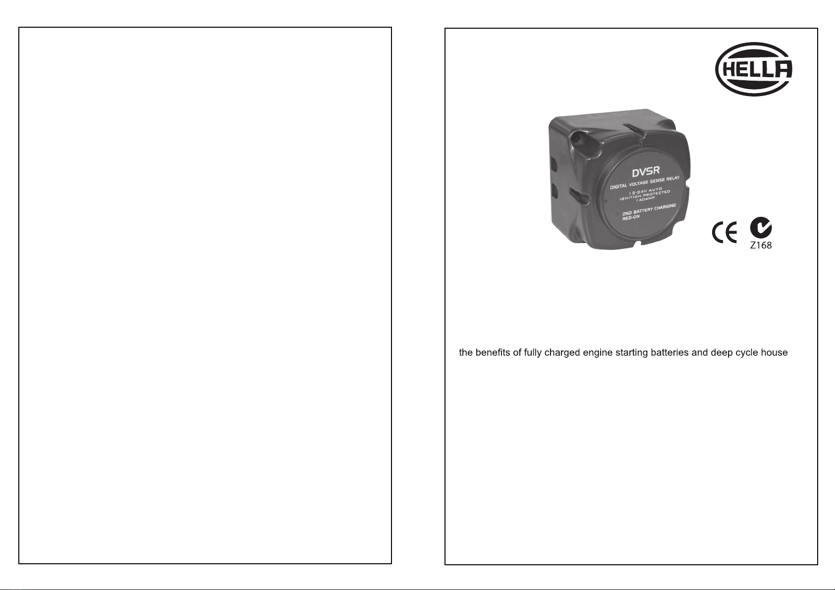
Hella 3099 User manual
Manufactured for HELLA by BEP Marine Limited
HELLA-New Zealand Limited
81-83 Ben Lomond Crescent
Pakuranga, Auckland, New Zealand
PO Box 51-427, Auckland 2140
DIGITAL VOLTAGE
SENSITIVE RELAY
HELLA Part No: 3099
Dual battery charging made easy
V
Modern charging systems must be able to safely charge two or more
different types of batteries from one engine. Now, thanks to the DVSR
(Digital oltage Sensitive Relay), 4WD, boat and caravan owners can enjoy
batteries with one easy-to-install charging system.
Operation and Installation Instructions
Features and Benefits
• Very low power consumption (<2mA)
• Multi-voltage, auto selects between 12VDC or 24VDC
• Digital technology for high efficiency and accuracy
• Dual battery bank voltage sensing
• Output for optional remote mounted status LED
• Optional switching circuit activates DVSR or switches it to zero power
consumption storage mode
• Protects start batteries from becoming flat
• High capacity (140A) design allows full alternator charging of heavily
discharged batteries
• Ignition protected
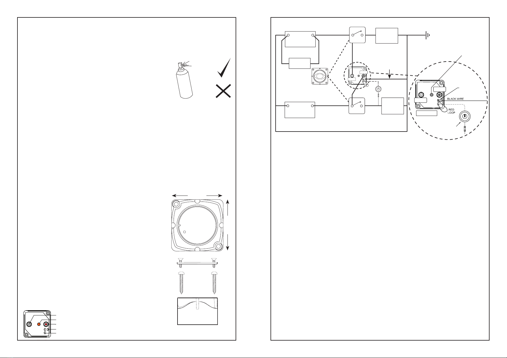
Optional Ignition Conrtol/Storage Mode (red wire):
Cut the end of the red looped wire (end closest to red dotted “Start Batt Positive +”
stud) where it joins the PCB/potting connect the remaining tail to the ignition/start
switch. With this feature selected the DVSR will only operate when the ignition key
is in the “ON” position (i.e. engine running). With the ignition switch “OFF”, current
draw of the DVSR will be zero Amps.
Optional Storage Mode :
Cut the red looped wire (as detailed above in “Ignition Control”) then connect to the
output from an ON/OFF switch. Connect the input of the switch to a fused positive
supply (+ 8-32V DC). With the switch in the ON position the DVSR will operate as
normal. With the ON/OFF siwtch OFF, the DVSR will not operate and the DVSR
current draw will be zero Amps.
Optional Remote LED indicator output (Orange sticker on circuit board) :
Cut silicon potting from above the orange sticker on the circuit board. Remove the
orange sticker and solder a wire to solder-pad on the circuit board. Repair the potting
with either silicon sealer, silicon grease, or marine grease. Connect the soldered wire
to negative leg of LED, connect the LED positive leg to fused 12V positive supply.
For 24V supply, use a 2.2K (1/4W) resistor on positive supply.
DVSR Operation Explained - Charging: The DVSR is connected between two battery
banks. When the DVSR senses a charging voltage (13.4V DC or 26.8V DC) on either
of the banks, it automatically activates and joins the two battery banks after a short
delay (5 seconds), so they are charged as one battery bank.
Isolation: When the DVSR senses that batteries are not being charged (voltage drops
to 12.75V DC or 25.35V DC) the DVSR deactivates following a 20 second delay,
separating the combined battery banks into two isolated banks.
Optional Storage Mode: This can be used where the boat/vehicle is stored for long
periods without any battery charging, but with the batteries still connected. Power
consumption is zero when this is activated. Alternatively, the storage mode can be
wired via the ignition switch, so the DVSR can only operate when the engine is
running. This provides optimal protection of electronics from electrical spikes, zero
power consumption when ignition is off, and acts like a single sensing VSR as DVSR
will only activate when engine alternator is charging.
IMPORTANT! It is recommended that the DVSR is fitted by a qualified marine/
automotive electrician. Please follow the installation instructions supplied. If
installation is not correct, the unit mayu not perform to its designed potentil. If in
doubt, consult your local dealer. It is the installer’s role responsibility to install and
use this product in a manner that will not cause accidents, personal injury or property
damage.
DVSR
DIGITAL VOLTAGE SENSE RELAY
12-24V AUTO
IGNITION PROTECTED
140AMP
2ND BATTERY CHARGING
RED-ON
12/24 Volt Selection, and First Powering:
When the DVSR is first powered, it will sample the power supply then decide whether to enter
12 volt (7-15.9 volts), or 24 volt (16 – 32 volts) mode. LED will flash rapidly while this occurs.
Please double check voltage in case batteries are flat, or another power source (e.g. solar panel)
is affecting the voltage. Once the 12 or 24 volt mode is selected, the DVSR will remain in this
mode until power is disconnected.
IMPORTANT!
Read before installing. Use only “plastic safe” corrosion inhibiting
sprays. Do not wipe solvents/petrochemicals onto any plastic part
of the DVSR. These units are fully sealed, so they do not require any
other form of water proofing. The DVSR has been designed to be
water resistant but is not designed to be partially or fully submerged.
The main studs have been tinned to inhibit corrosion (petroleum base
grease may be used on these for further protection, but should not be used on plastic parts).
ALTERNATOR VS BATTERY BANK SIZE:
The charging alternator’s amperage output should be between 20% and 35% of the battery
bank size in Amp Hours. e.g. 220AH bank = 44 - 77A alternator
NOTE: Alternator size must not exceed 140A, or 125A if alternator is “hot rated” with a
3 stage regulator
Start Batt Positive + (Large stud marked red): Connects to the battery (Live) side of the
Start Battery Isolator Switch
House Batt Positive + (Large stud): Connect to the battery (Live) side of the House Battery
Isolator Switch
Negative (Black wire): Connect to battery negative (ensure both battery banks share common
negative, see diagram)
INSTALLATION
Remove base to expose studs and cables.
Connect the DVSR to the back of the battery isolating switches,
ensuring that the battery cables are correctly sized. The LED on
the front of the DVSR should be visible, as it will instantly
show when it is in operation.
Use countersunk screws for fastening base down.
Use Pan head screws (supplied) for fastening the DVSR onto
the base.
68 mm
68 mm
NOTE: Both batteries must be the same voltage, either 12V or 24V DC.
NOTE: This diagram
is a guide only showing
DVSR connections
and not intended as a
full electrical systems
wiring diagram.
Start
Battery
–+Engine
Power
Black Cable
(Supplied)
Battery
Charger
P/N 3099
House
Battery
–+Accessories
REAR VIEW
ENGINE
BATTERY
Battery Isolating
Switches
BLACK
RED
Plastic safe
Petroleum
based
solvents
HOUSE BATT
POSITIVE +
START BATT
POSITIVE +
LED codes:
OFF: DVSR is disengaged, battery banks are not connected
ON: The DVSR is engaged, battery banks are combined
Brief flash every 5 seconds: DVSR is disengaging
Fast flash: System voltage is either too high or too low, check
electrical system
House Batt Positive +(Tinned stud)
Orange sticker (Remote LED connection point)
Start Batt Positive + (Tinned stud)
Black wire - (Negative)
Red wire(Ignition control/Storage mode)
Wiring Diagrams
DVSR Connections
SPECIFICATIONS
Current: 125 Amps Continuous, 140 Amps Intermittent
Ignition Protected UL 1107
Auto Voltage Sensing 12VDC or 24VDC (max 32VDC)
Power Consumption (Standby) 1.8mA (1.6mA at 24 VDC)
Power Consumption (Storage Mode) 0mA
Cut In/Cut Out Voltages 13.4V (26.80V) / 12.75V (25.35V)
CONNECTIONS:
Locate DVSR to minimize cable lengths and ensure all cables are sized correctly for
minimum voltage drop (see table below).Voltage drop will decrease effectiveness of
the DVSR, reduce charge efficiency, and could damage the DVSR and surrounding
devices through excessive heat build-up. Ensure all connections are tight and suitable
for the installation. Use a neutral cure sealant to seal any cut cable ends.
DVSR POWER SUPPLY :
The DVSR takes its power supply from the red paint marked stud (Start Batt Positive +)
for standard installations. When the optional Ignition Control/Storage installation is
chosen, the DVSR power supply is supplied via the fused secondary supply and
switch, to the DVSR’s red looped wire. With the switch (or ignition switch) turned off,
the DVSR cannot activate.
OPTIONAL CUT
HERE AND JOIN
OTHER END FOR
IGNITION OR
STORAGE
MODE CONTROL
OPTIONAL SWITCH FOR
IGNITION OR STORAGE
MODE CONTROL
FUSE
START BATT
POSITIVE +
HOUSE BATT
POSITIVE +
START BATT
POSITIVE +
HOUSE BATT
POSITIVE + REAR VIEW
OPTIONAL
ORANGE
Other Hella Relay manuals


