manuals.online logo
Brands
  1. Home
  2. •
  3. Brands
  4. •
  5. Hellenbrand
  6. •
  7. Water System
  8. •
  9. Hellenbrand 109248 User manual

Hellenbrand 109248 User manual

1
Owner’s Manual
Manufactured by:
HELLENBRAND, INC.
404 Moravian Valley Road
Waunakee, Wisconsin 53597
Phone: 608-849-3050 • Fax 608-849-7398
Web: www.hellenbrand.com • Email: [email protected]
Water Management System
Patent Pending
800378
1/13/16-LBRY
©2011-2016
2
Congratulations on your purchase of the Hellenbrand Water Management System. This patented water reuse system
recovers water that normally would be discharged to the drain and stores it and uses the water to ush the toilets, helping
preserve our most precious natural resource, water. This owner’s manual is designed to assist owners and installers with
the operation, maintenance, and installation of your new water reuse system. It is our sincere hope that this manual is clear,
concise, and helpful to both the owner and installer. We have included detailed instruction diagrams and provided general
operating information of the various components.
Questions? Should you have any questions regarding the installation, operation or servicing of this system, please contact
the dealer you purchased this system from. Your dealer will be familiar with your particular situation and the required volume
and ow required of your toilets and should be able to address your concerns promptly and efciently.
TABLE OF CONTENTS
Installation Data.................................................................................................................................................................... 2
Installation Drawings ......................................................................................................................................................... 3-4
Installation Instructions...................................................................................................................................................... 5-6
Wiring ................................................................................................................................................................................... 7
Motorized Alternating Valves (MAVs) ................................................................................................................................ 8-9
Programming Sheets.......................................................................................................................................................... 10
Delivery Pumps ..............................................................................................................................................................11-12
Pressure Tank................................................................................................................................................................ 13-14
Float System.................................................................................................................................................................. 15-16
Storage Tanks................................................................................................................................................................ 17-18
INSTALLATION DATA
Waste Water Management System (WMS) Model: _______________________________________________________
Date of Installation: ________________________________ Installed By: _________________________________
Number of toilets fed by WMS: _______________________
Volume required to ush:____________________________ Pressure required to ush:_______________________
3
INSTALLATION DRAWING
4
MAV INSTALLATION DRAWING
5
1. Place water softener and WMS storage tank on clean, level and solid location.
2. Install softener according to installation instructions in softener manual.
3. Run drain line from softener to Motorized Alternating Valve (MAV) on storage tank and run drain line from MAV to
drain in pipe capable of handling softener backwash ow rate.
4. Connect overow to drain with proper air gap.
5. Install cold soft water make-up line to storage tank.
6. Install make-up oat by ushing debris from lines before tting. Mount valve horizontally in tank with outlet point-
ing down. Tape inlet thread with Teon tape. Set bottom stop at desired on position and tie off cord at end of
arm with rm knot (keep bottom stop away from tank outlet). Ensure weighted oat is in correct position and cut
excess cord to desired length. Avoid mounting valve near overow outlet.
7. Plumb drains of any other reclaimable water supplies to storage tank. This is a “clear water” only reuse system and
not designed for gray water or black water or storm water. Besides other water treatment equipment discharge,
may use water including but not limited to non-contact cooling water, condensate drainage from refrigeration com-
pressors and air conditioning equipment, drainage water for equipment chilling purposes and cooled condensate
from steam heating systems.
8. Install delivery pump.
9. Turn on water to make-up line for initial ll of storage tank.
10. Install pressure gauge and sample tap.
11.
If using the optional carbon lter for de-chlorinating water prior to toilets, install and add cartridge to the housing.
12. Prime the delivery pump.
13. Pressurize non-potable water supplies and check for leaks. Label re-use piping according to state and local re-
quirements. In Wisconsin, see 82.40 of plumbing code, table 82.40-1a, below.
14. Place (1) chlorine tablet in oating chlorine dispenser and place in water.
INSTALLATION INSTRUCTIONS
FOLLOW ALL STATE AND LOCAL PLUMBING CODES
Supply Tag and Band Color Tag Shape Tag Size Tag Legenda
Potable Green Round 3” diameter Safe Water
Nonpotable Yellow Triangle 4” Sides Nonpotable Water or
Not Safe for Drinking
Reuse
(Nonpotable) Purple Triangle 4” Sides
Nonpotable Water or
Not Safe for Drinking or
Specic Useb
Device
SpeciccGray Triangle 4” Sides Specic Useb
a All nonpotable water outlets shall be identied at the point of use for each outlet with the following legends or as otherwise approved by the department.
b Tag should reect the intended use.
c Servicing an individual or similar plumbing xtures or appliances.
DEPARTMENT OF COMMERCE – COMM 82.40
TABLE 82.40-1A DISTRIBUTION AND SERVICE
6
• Do not use vaseline, oils, other hydrocarbon lubricants or spray
silicone anywhere. A silicon lubricant may be used on black
o-rings but is not necessary. Avoid any type of lubricants,
including silicone, on red or clear lip seals.
• Do not use pipe dope or other sealants on threads. Only
teon tape may be used on threads. Teon tape is not
necessary on the nut connection or caps because of o-
ring seals.
• The pipe size for the drain line should be a minimum of 5/8”.
Backwash ow rates in excess of 7 gpm or length in excess
of 20’ require 1” drain line.
1. Place the conditioner where you want to install it, making sure
it is on a clean, level and rm base.
2. Do all necessary plumbing (inlet to inlet, outlet to outlet and
drain line to drain). The control valve, ttings and/or bypass
are designed to accommodate minor plumbing misalignments
but are not designed to support the weight of a system or the
plumbing.
3. When assembling the installation tting package (inlet and
outlet), connect the tting to the plumbing system rst and
then attach the nut, split ring and o-ring. Heat from soldering
or solvent cements may damage the nut, split ring or o-ring.
Solder joints should be cool and solvent cements should be
set before installing the nut, split ring and o-ring. Avoid get-
ting primer and solvent cement on any part of the o-rings, split
rings, bypass valve or control valve.
4. A jumper ground wire should be installed between the
inlet and outlet pipe whenever the metallic continuity of
a water distribution piping system is interrupted. Install
grounding strap on metal pipes.
5. The drain connection may be made using either 5/8” poly tube
(If using 5/8” poly tube for drain, compression nut, and the poly
tube insert must be purchased separately) or a 3/4” female
adaptor. If soldering joints near the drain, must be done prior
to connecting the drain line ow control tting. Leave at least
6” between the drain line control tting and solder joints when
soldering pipes that are connected on the drain line control
tting. Failure to do this could cause interior damage to the
drain line ow control tting.
6. The brine rell ow control assembly is installed in an easy
to access rell elbow located on top of the control valve. The
rell ow control assembly is attached to the control valve
with a locking clip. The locking clip allows the elbow to rotate
270 degrees so the outlet can be orientated towards the brine
tank.
7. Remove 3/8” black brine line from brine tank. Connect to
control valve at brine line elbow, using white plastic insert
tubing found on locking clip. See below.
8. Make sure oor is clean and level beneath brine tank. No grid
is required with standard brine tanks as softener is programmed
as prell.
A 1/2” (inside diameter) gravity drain line should be connected
to the overow elbow on the side of the brine tank and run to
a drain below the level of the elbow. This overow drainage
system provides protection from water damage in the event of
a brine shut-off malfunction. Tubing is not provided to do this.
In all cases where an overow could result in water dam-
age for various reasons, this overow protection must be
used. Do not connect the tubing to the drain line on the
control valve discharge line and do not run this line above
the overow elbow height at any point. Provide air gap.
INSTALLATION INSTRUCTIONS
(All electrical & plumbing should be done in accordance to all local codes)
Drain
Connection
Brine Line
Connection
Bypass
7
1 V3722 Strain Relief Cover Backplate 1
2 V3804 Screw 6x1/2 PHPN T-25 SS 1
QTY.
ITEM NO. ORDER NO. DESCRIPTION
1. Remove valve cover and drive bracket assembly.
2. From the valve cover side, use a punch and ham-
mer to remove the knock out plug.
3. Smooth the edge of the hole if needed.
4. Use pliers to remove one or both tabs as needed.
5. Run cable(s) through the strain relief feature on the
back plate.
6. Reinstall the drive bracket assembly and connect
the cables. Adjust cable length if necessary. Do
not let the cables come in contact with the drive
gear assembly.
7. Install strain relief cover and secure using screw.
STRAIN RELIEF COVER KIT
WIRING OPTION 1:
MAV Drive Cable must be connected to PC Board prior to programming or error 116 will result.
If installing any place other than brine tank, allow 4” of clearance above for service access. After plumbing completed, next
installation step is to provide access for MAV cable through back of valve. This is done by breaking off plastic tabs on back
plate to thread cable through back and attach to two-pin connection labeled DRIVE on PC board.
1. Remove valve cover.
2. Remove drive bracket by lifting two tabs at top of back plate and lift bracket out of bottom supports; set aside.
3. With needle nose pliers, break plastic tab off bottom of LEFT cable guides so MAV cable can t through.
4. Route MAV drive cable through left side of back plate along with meter cable and weave through guides, push
snugly into place. Allow about 1 foot of cable to attach to PC board. Snap drive bracket into place and route MAV
cable to the left of PC board and plug into two-pin connection marked DRIVE on PC board. Verify all connections
are securely plugged into PC board.
5. Replace cover, plug 12V transformer into outlet that cannot be switched off and proceed to programming.
WIRING OPTION 2:
WIRE MAV TO PM SERIES CONTROL
8
Exploded Parts View
Drawing No. Order No. Description 102032(F-F) 102033(M-M)
1 101471 MAV/NOHWBY COVER ASY 1 1
2 102095 WS MOTOR ASY 8 FT 1 1
3 106139 SCREW #8-3/4 PHPN T-25 SS 3 3
4 106133 WS1.5 & 2Alt/2BY REDUCGEARCVASY 1 1
5 101746 WS1 DRIVE GEAR 12X36 3 3
6 106134 WS2 BYPASS REDUCTION GEAR AXLE 3 3
7 106140 SCREW 1/4-20 X 3/4 BHSCS SS 4 4
8 106141 MAV/NOHWBY 1/125/15 DRIVE ASY 1 1
9 106142 MAV/NOHRD 1/125/15 PISTON 1 1
10 106143 MAV/NOHWBY 1/125/15 STACK ASY 1 1
11 15-V3504FF MAV BODY 1/125 ASY F-F 1 N/A
12 15-V3504MM MAV BODY 1/125 ASY M-M N/A 1
13 102141 WS1 NUT 1 QC N/A 2
14 102437 WS1 SPLIT RING N/A 2
15 102165 O-RING 215 N/A 2
Not Shown 15-V3474-01 WS ALT MAV 1/125 CORD 8FT BLK 1 1
Common Port
THREE-WAY, 1” MAV-FNPT, PART NUMBER: 102032
9
Exploded Parts View
Drawing No. Order No. Description 105988 15-V3071BSPT
1 101471 MAV / NOHWBY COVER ASSY 1 1
2 102095 WS MOTOR ASY 8 FT 1 1
3 106139 SCREW #8-3/4 PHPN T-25 SS 3 3
4 106133 WS1.5&2ALT/2BY REDUCGEARCVRASY 1 1
5 101746 WS1 DRIVE REDUCING GEAR 12X36 3 3
6 106134 WS2 BYPASS REDUCTION GEAR AXLE 3 3
7 106140 SCREW 1/4-20 X 3/4 BHSCS SS 4 4
8 106141 MAV/NOHWBY 1/125/15 DRIVE ASSY 1 1
9 106142 MAV/NOHRD 1/125/15 PISTON 1 1
10 106143 MAV/NOHWBY 1/125/15 STACK ASSY 1 1
11 106144 MAV BODY 1.5 NPT 1 N/A
12 V3525BSPT-01 MAV BODY 1.5 BSPT N/A 1
Not Shown 106137 WS ALT CONNECT CORD 8FT BLK 1 1
THREE-WAY, 1.5” MAV, PART NUMBER: 105988
10
\
ENTER VALVE TYPE 1.0 / 1.25 / 1.5 / 2.0 / 2.0L
ALTERNATOR SYSTEM (As Needed) OFF
SET RINSE OPTION OFF
AUXILIARY MAV TRIGGER RECLAIM
RECLAIM START 20:00 (Backwash +12 mins)
RECLAIM DURATION 48:00 (Remainder of Brine/Slow Rinse)
AUXILIARY INPUT OFF
SET CYCLE 1 FILL
SET CYCLE 2 SOFTENING
SET CYCLE 3 BACKWASH
SET CYCLE 4 REGENERANT DRAW DN
SET CYCLE 5 RINSE
SET CYCLE 6 END
ALTERNATE FILL TRIGGER OFF
Press NEXT & for 3 seconds.
Choose “SOFTENING”
Or “FILTERING”
“SOFTENING”
1 – FILL # of SALT SEE SPEC
2 – SOFTENING TIME 120
3 – BACKWASH TIME SEE SPECIFICATION
4 – DRAW TIME SEE SPECIFICATION
5 – RINSE TIME SEE SPECIFICATION
CAPACITY SEE SPECIFICATION
Set RESERVE AUTO
Set REGENERATION TYPE DELAYED
RELAY DRIVER 1 OFF
RELAY DRIVER 2 OFF
SERVICE CALL OFF
Press NEXT &  for 3 seconds.
SET HARDNESS PER APPLICATION
SET DAYS BETWEEN REGEN 14
SET HOUR OF REGENERATION 2:00 AM
SET MINUTE OF REGENERATION 2:00 AM
WATER MANAGEMENT SYSTEM PROGRAMMING:
or select cycle sequence
options as desired
Use   arrows to select
H125 Series is factory
programmed with ll
cycle as nal cycle.
Press  and  arrows to select desired option. Press NEXT to go to next step (Press REGEN to go to previous step)
Press NEXT &  for 3 seconds or until display changes. Release and Press NEXT &  for 3 seconds again until valve
type is displayed.
11
AQUATECH WATER PUMPS
550 Series Super Flow Pump
Key Operational Benets:
• Unparalleled performance
• 1.5 to 5.5 GPM (20 lpm) ow
• Up to 100 psi (7 bars) pressure
• 7 year design life
• Highly efcient
• Minimal pulsations
• Whisper quiet at lower ows
• Self priming
• Can run dry without damage
• Chemically resistant versions
Technical Specications:
OPERATION: The 550 pump can draw water from a holding tank and pressurize it, or boost the pressure from a low
pressure source. It is designed to operate intermittently, but most versions can run continuously for several hour inter-
vals. It can be operated in demand mode controlled by an integral pressure switch, or in delivery mode controlled by an
external power switching device.
POWER: The power demand varies depending on ow and pressure from 50W to 200W. Motors are available in various
congurations from 12 VDC to 230 VAC. Transformers or DC power supplies are optional and must be ordered sepa-
rately if applicable. Standard terminations are 12” long 16 AWG lead wires with a stripped end, connectors or cords with
plugs.
MOUNTING: A steel mounting base with four hollow rubber grommets is standard and included at no extra cost. The
pump may be mounted in any position.
FITTINGS: The standard pumphead has a .750” port opening that accepts “quick-connect” beverage style O-ringed barb
ttings, or John Guest ttings that can be used with 3/8”, 1/2”, 5/8” or 3/4” tubing. The pump can also be ordered with a
1/2 NPT female port. Always consult the factory for recommendations that will optimize your system.
DELIVERY PUMP OPTION:
Part No. Description
107368 4.90 GPM open ow – QD ports – 60 PSI – 115 volt with cord
2.15 GPM @ 40 PSI - 115 Volt
12
GRUNDFOS MQ - MQ 3-45
Compact, all-in-one unit for your home water supply
Easy to select
The Grundfos MQ is a compact pump and pressure
boosting unit specially designed for home water supply.
It is a reliable and very easy-to-operate unit that can
be tted almost anywhere. The pump is self-priming,
which means that it is capable of drawing water from
a well depth of down to 8m. As the MQ has a built-in
pressure tank, you do not need a space-consuming tank.
The MQ pump is also ideal for boosting pressure
from elevated or sub-terrain water storage tanks or from
the water mains.
Easy to install
The Grundfos MQ pump is easy to install. The
compact, horizontal design makes the pump easy to
place even where space is limited. The outlet pipe con-
nection can be angled up to 5” to t existing pipework.
Due to the built-in pressure tank and integrated
start/stop features there is no need for adjusting a sepa-
rate pressure switch.
The MQ is water-cooled and therefore has no noisy
cooling fan. As it is self-priming, it is not necessary to
allow free space around the pump for priming.
Easy to operate
Operation of the Grundfos MQ pump is simple and
easy. Once installed it needs only a push on the “On”
button to provide many years of reliable service. The
actual settings are clearly indicated by indicator lights
on the user-friendly control panel.
The MQ pump has a small built-in pressure tank,
sufcient to ensure that water is readily available from
the tap. The pump starts automatically as soon as the
tap is opened and no loss of pressure is felt.
Unique user benets
The Grundfos MQ “anti-cycling” feature prevents
the pump from continuously starting and stopping in the
event of a dripping tap or minor leak in the system.
The MQ pump has built-in dry-running protection.
If for any reason water is not available, the pump auto-
matically switches off. It will subsequently attempt to
re-start every half hour for up to 24 hours until water is
again available.
The pump also has a built-in thermal protection. If
it overheats, the pump will stop immediately. After a
30-minute cooling-down period, the pump will automati-
cally restart.
Corrosion-free
The Grundfos MQ pump is built for long-term,
trouble-free operation. It is made of weatherproof,
corrosion-resistant materials and can, if necessary, be
placed outdoors.
A drain plug enables easy draining of the pump.
This is especially convenient if the pump is installed in
a front-risk location such as a holiday cottage. The MQ
pump is suitable for rainwater and will not contaminate
drinking water.
User-friendly control panel
The Grundfos MQ features an easy-to-use control panel
with indicator lights for indication of
• pump on
• auto-reset
• alarm (dry-running or overheating)
In the even of dry-running, the pump will stop and
afterwards attempt to restart automatically. Restarting
can also be done manually. If required, the auto-reset
function can be disabled.
DELIVERY PUMP OPTION:
Description
6PM @ 49 / 12GPM @ 36 PSI
13
FRO Series
Reverse Osmosis Storage Tanks
Your customers
demand the
best!
Meet their
demands with
FLEXCON
FRO Series
Reverse Osmosis
StorageTanks!
Flexcon Industries has established itself as a leader in
pressure tank technology.The FRO Series reverse
osmosis storage tanks are the latest in a long line of
innovative, high quality products. Made of superior
materials and meeting the stringent standards of NSF 58,
these tanks are available in 3 sizes.At the heart of the
tank is a 100% butyl rubber diaphragm that has been
post cured to eliminate any unwanted taste and odors.
Combined with a polypropylene liner it keeps system
water contained in a sealed water chamber. A double
gasketed stainless steel connection assures the integrity
of the water treatment system.The bottom dome of the
smaller tanks has been enhanced with 4 rounded legs to
insure installation stability and the 14 gallon tank includes
a rugged poly base. Each tank is pressure tested and has
a maximum working pressure of 125 PSI.
•Stainless Steel
Connection
•100% Butyl
Diaphragm
•Polypropylene
Liner
• Enhanced
bottom dome
•NSF Standard 58
listed
Flexcon Industries has established itself as a leader in pressure tank technology. The FRO Series reverse osmosis
storage tanks are the latest in a long line of innovative, high quality products. Made of superior materials and meeting
the stringent standards of MSF 58, these tanks are available in 3 sizes. At the heart of the tank is 100% butyl rubber
diaphragm that has been post cured to eliminate any unwanted taste and odors. Combined with a polypropylene liner
it keeps system water contained in a sealed water chamber. A double gasketed stainless steel connection assures the
integrity of the water treatment system. The bottom dome of the smaller tanks has been enhanced with 4 rounded legs
to insure installation stability and the 14 gallon tank includes a rugged poly base. Each tank is pressure tested and has a
maximum working pressure of 125 PSI.
Features:
• Stainless Steel Connection
• 100% Butyl Diaphragm
• Polypropylene Liner
• Enhanced bottom dome
• NSF Standard 58 Listed
PRESSURE TANKS FOR DELIVERY SYSTEM
Part No. Description
104615 3.2 Gallons
104616 4.4 Gallons
14
Parts for 103697(CPVC) & 103698*(PVC-80)
ITEM # QUA PART # DESCRIPTION
104606 WR-60 TANK 20 GALLONS
1 1 100469 1" T x T elbow CPVC
2 1 100634 1" x 10" nipple CPVC
3 1 100359 1" X 1/4" bushing CPVC
4 1 100633 1/4" X close nipple CPVC
5 1 102844 1/4" FNPT x 3/8" JG VALVE
4
Exploded view for
103695/103696/103967/103968
Dwg #: 800144
04/06/2005
Rev 3-9-11 AGM
Waunakee, WI
(608)849-3050
J.MILLER
ITEM # QUA CPVC PART # *PVC80 PART # DESCRIPTION
104474 104474 WR-100 TANK 32 GALLONS
104475 104475 WR-140 TANK 44 GALLONS
104476 104476 WR-260 TANK 85 GALLONS
108490 108490 WR-360 TANK 120 GALLONS
1 1 109800 100728 1-1/4" TEE TxTxT
2 1 100635 100624 1-1/4" x 12" Nipple
3 1 109801 100769 1-1/4" Ball Valve
4 1 100360 109798 1-1/4"x1/2" Reducer Bushing
5 1 100420 100420 1/2” Tube x MNPT ADPT
6 1 109799 100622 1-1/4" x CL Nipple TxT
Parts for 103696
5
5
21
3
ITEM # QUA PART # DESCRIPTION
104615 FRO-122 3.2 GALLON TANK
104616 FRO-132 4.4 GALLON TANK
104610 FRO-1070 14 GALLON TANK
1 1 102844 1/4" FNPT x 3/8" JG VALVE
Parts for 103695
1
1
FRO-122
FRO-132
FRO-1070
WR-100
WR-140
WR-260
WR-360
Hellenbrand
SET TANK AIR
PRESSURE TO
8PSI
21
SET TANK AIR
PRESSURE TO
8PSI
WR-60
4
3
6
SET TANK AIR
PRESSURE TO
8PSI
*103698 (PVC-80) is not approved for potable use in the state of WI
15
FLOAT ASSEMBLY, PART NUMBER 109148
16
17
18-INCH ROUND BRINE TANKS
ORDER NUMBER DESCRIPTION
104492 18x40 Tank with Blow Molded Cover
TANK SIZE LIQUID CAPACITY SALT CAPACITY DIAMETER HEIGHT W/ LID SHIPPING WEIGHT MASTER CARTON
in. gal. liters lbs. Kg in. cm in. cm lbs. Kg ft.3/units per
18 x 40 43 163 450 205 181⁄247 403⁄4104 15 6.8 9/1
18 inch blow molded round brine
tanks offer a refreshing look in the
residential and light commercial tank
eld. Durable materials and the latest
in plastic processing technology
provide trouble-free performance.
Ultraviolet inhibitors (UVI) are now
standard in all tanks except black,
which has a natural resistance to the
sun's rays. Three different sizes are
available.
• Attractive design to meet customer
appeals with four modern stock
colors to choose from — almond,
blue, black and white. (Custom
colors available.)
• Blow molded from high-density
polyethylene to give exceptional
environmental stress-crack
properties providing years of
trouble-free service.
Advantages:
18x33 Brine Tank with
Black Injection Molded Cover
18x40 Brine Tank with
Blow Molded Cover
18
24” AND 30” COMMERCIAL/INDUSTRIAL BLOW MOLDED TANKS
Hellenbrand now offers both 24"
and 30" round blow molded tanks.
The introduction of the 30" diam-
eter tank makes it the largest blow
molded tank for commercial/indus-
trial applications. Like the 24" round
tank, the 30" tank is molded of high
density polyethylene for exceptional
stress and crack resistant properties.
These tanks are ideal for industrial
and commercial use and the 30"
tank feature heavy wall thickness for
increased durability.
Injection molded grids are available
for both 24" and 30" tanks and use
11⁄2" schedule 40 PVC pipe for leg
supports. The legs can be cut to any
length for easy grid height adjust-
ment. A precut leg kit for the 24" grid
is also available, giving it an overall
grid height of 101⁄4".
30x50 Black Brine Tank 24x50 Black Brine Tank
ORDER NUMBER DESCRIPTION LIQUID
CAPACITY
SALT
CAPACITY
HEIGHT W/
LID DIAMETER SHIPPING
WEIGHT
CARTON
SIZE
UNITS
PER
CARTON
104497 24 x 50 Black Brine
Tank
100 gal./ 378
liters
900 lbs./ 408
Kg
51.5 in/ 131
cm
24.5 in./
62 cm
27.25 lbs./
12.4 Kg 18 ft.31
104499 30 x 50 Black Brine
Tank
150 gal./ 579
liters
1400 lbs./ 640
Kg
52.5 in/ 133
cm
31 in./
79 cm
49 lbs./ 22.3
Kg 30 ft.31
CHLORINE DISPENSER OPTION
“ A proven leader in chlorine dispensers
with years of customer use and satisfaction
in the pool and spa market”
Place (1) 1” trichlor tablet in dispenser.
Adjust feed rate by turning collar. The larger
the opening, the greater the feed rate.

This manual suits for next models

1

Other Hellenbrand Water System manuals

Hellenbrand 3000 Series User manual

Hellenbrand

Hellenbrand 3000 Series User manual

Hellenbrand ProMate 6.5 User manual

Hellenbrand

Hellenbrand ProMate 6.5 User manual

Hellenbrand PM6.O-IC-2.0 Series User manual

Hellenbrand

Hellenbrand PM6.O-IC-2.0 Series User manual

Hellenbrand Promate 6.0-DMT User manual

Hellenbrand

Hellenbrand Promate 6.0-DMT User manual

Hellenbrand promate 6.0 User manual

Hellenbrand

Hellenbrand promate 6.0 User manual

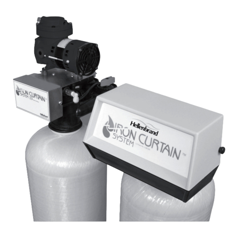
Hellenbrand Iron curtain System 2.0 User manual

Hellenbrand

Hellenbrand Iron curtain System 2.0 User manual

Hellenbrand ProMate 1 User manual

Hellenbrand

Hellenbrand ProMate 1 User manual

Hellenbrand Iron curtain System 2.0 User manual

Hellenbrand

Hellenbrand Iron curtain System 2.0 User manual

Hellenbrand WaterMate 3.2 User manual

Hellenbrand

Hellenbrand WaterMate 3.2 User manual

Hellenbrand promate 6.0 User manual

Hellenbrand

Hellenbrand promate 6.0 User manual

Popular Water System manuals by other brands

Hilti DD-REC1 operating instructions

Hilti

Hilti DD-REC1 operating instructions

Pelican Calcite Cartridge System owner's manual

Pelican

Pelican Calcite Cartridge System owner's manual

AmeriWater MediQA Diagnostics guide

AmeriWater

AmeriWater MediQA Diagnostics guide

Tollco WaterFuse Apartment User's manual & installation instructions

Tollco

Tollco WaterFuse Apartment User's manual & installation instructions

Biral ComBo HP-E Series Installation and operating instructions

Biral

Biral ComBo HP-E Series Installation and operating instructions

Nikken Aqua Pour operating manual

Nikken

Nikken Aqua Pour operating manual

oventrop Regumaq X-25 operating instructions

oventrop

oventrop Regumaq X-25 operating instructions

kinetic Arsenic Guard Homeowner's information

kinetic

kinetic Arsenic Guard Homeowner's information

AquaLiv A305 Usage & installation instructions

AquaLiv

AquaLiv A305 Usage & installation instructions

Kingspan BioDisc BAx Installation guidelines

Kingspan

Kingspan BioDisc BAx Installation guidelines

Latham COVERSTAR AutoDrain Usage and installation manual

Latham

Latham COVERSTAR AutoDrain Usage and installation manual

Midea MU1649-4 instruction manual

Midea

Midea MU1649-4 instruction manual

PREMIER TECH Rewatec NEO Installation and assembly guide

PREMIER TECH

PREMIER TECH Rewatec NEO Installation and assembly guide

Water Control PS-5 Troubleshooting and maintenance guide

Water Control

Water Control PS-5 Troubleshooting and maintenance guide

Sloan 110 installation instructions

Sloan

Sloan 110 installation instructions

First Sales XTS30 Installation instructions and owner's manual

First Sales

First Sales XTS30 Installation instructions and owner's manual

ACO Self Europoint Flat installation instructions

ACO

ACO Self Europoint Flat installation instructions

WaterLogic WL900 Service guide

WaterLogic

WaterLogic WL900 Service guide

manuals.online logo
manuals.online logoBrands
  • About & Mission
  • Contact us
  • Privacy Policy
  • Terms and Conditions

Copyright 2025 Manuals.Online. All Rights Reserved.