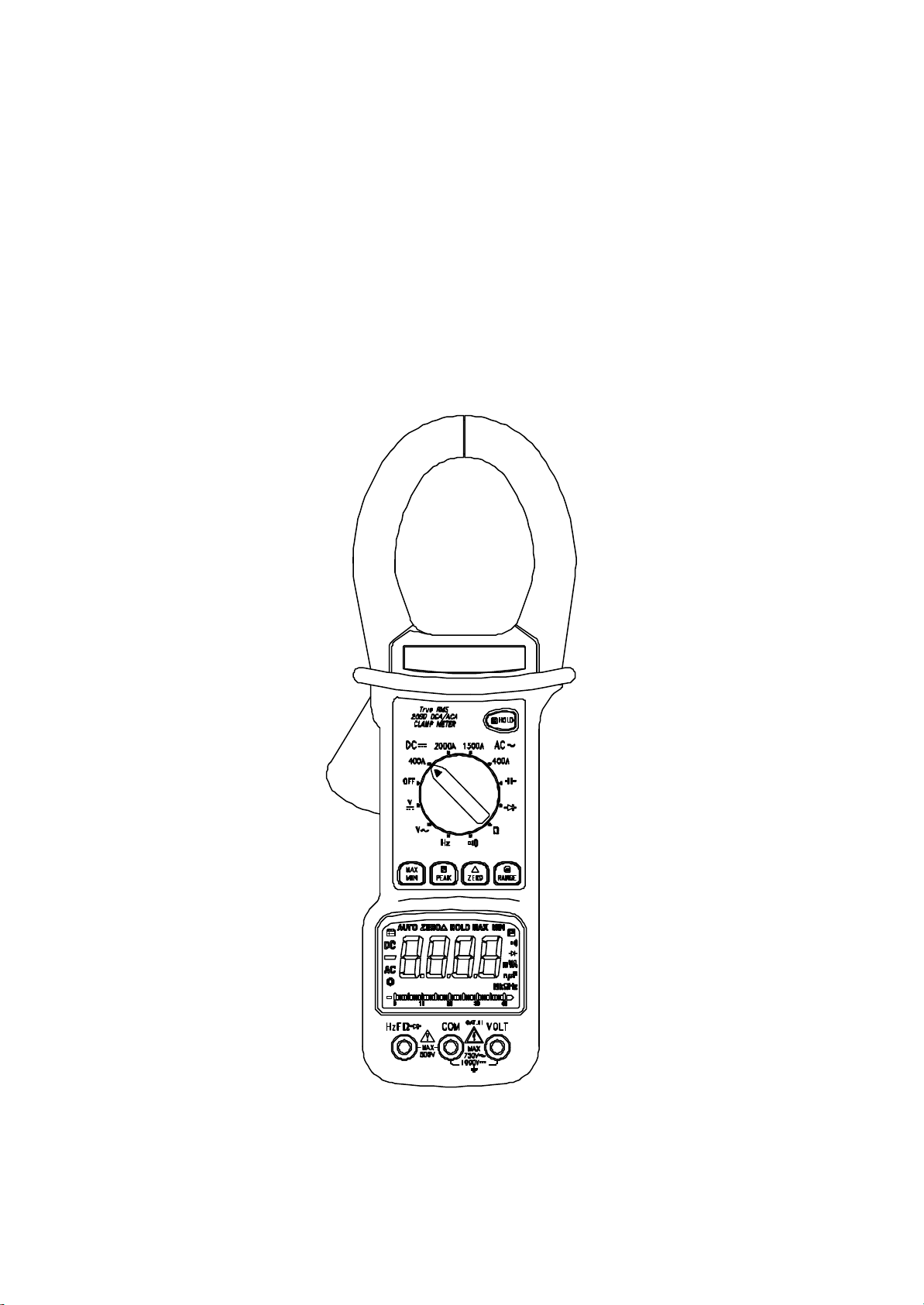
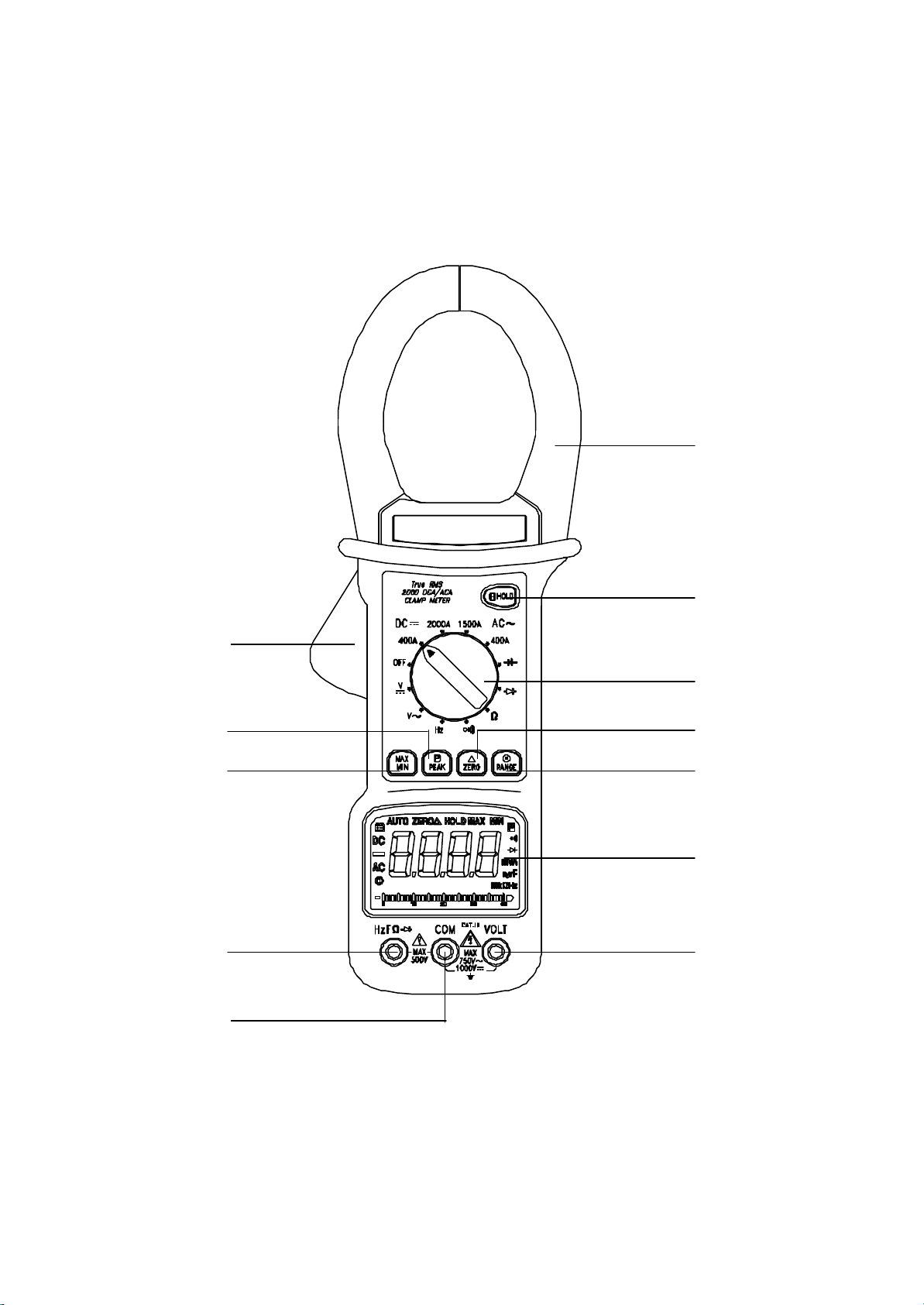
Hellermann Tyton 2608 User manual

OPERATINGINSTRUCTIONS
Model2608
DIGITALCLAMPMETER
2608.p65 ?2005/5/26, 下午 03:491

CONTENTS
INTRODUCTION---------------------------------------------------------1
UNPACKINGAND INSPECTION----------------------------------1
SAFETYPRECAUTIONS----------------------------------------------1
SAFETYINFORMATION----------------------------------------------3
INSTRUMENTLAYOUT-----------------------------------------------4
HOWTOMAKE MEASUREMENTS-------------------------------8
Voltage Measurements--------------------------------------------------------------8
CurrentMeasurements---------------------------------------------------------------9
ResistanceMeasurements----------------------------------------------------------9
ContinuityTesting --------------------------------------------------------------------10
Diode Testing -------------------------------------------------------------------------10
CapacitanceMeasurement--------------------------------------------------------11
Frequency Measurements---------------------------------------------------------11
SPECIFICATIONS------------------------------------------------------12
MAINTENANCE---------------------------------------------------------16
Replacing the Battery---------------------------------------------------------------16
2608.p65 ?2005/5/26, 下午 03:492

INTRODUCTION
Thismanualcontainsinformation and warningswhichmustbe followed to
ensuresafeoperation and retainthe meterinsafecondition.
1
The following safetyprecautionsmustbe observed toensuremaximum
personalsafetyduring the operation,serviceand repairofthismeter:
SAFETYPRECAUTIONS:
If anyofthe aboveitemsaremissing orarereceived inadamaged
condition,pleasecontactthe distributorfromwhomyou purchased the
unit.
Uponremoving yournewDigitalClampMeter(DCM) fromitspacking,you
shouldhavethe following items:
1.DigitalClampMeter
2.TestLead Set(one black,one red)
3.9-VoltBattery(installed inmeter)
4.Instruction Manual
UNPACKINGAND INSPECTION
Thisclampmeterisahandheld4000-countinstrumentthatisdesigned
foruseinthe laboratory,fieldservicing,athome,and anycircumstance
wherehigh currentmeasurementisrequired.The clampmeterisbuilt
withadesign offingerguardwhichensuresusersoperating the instrument
underasafetysituation;arugged casethatisshock resistantand fire-
retardant; and electronicoverload protection forall functionsand ranges.
Inaddition,acarrying case(optionalaccessory)isavailableforeasy
portabilityofthe meterand avoiding damage.
WARNING
READ"SAFETYINFORMATION"BEFOREUSINGTHEMETER.
2608.p65 ?2005/5/26, 下午 03:493

2
1.Read theseoperating instructionsthoroughlyand completelybefore
operating yourmeter.Payparticularattention toWARNINGSwhich
willinform youofpotentiallydangerousprocedures.The instructions
inthesewarningsmustbe followed.
2.Always inspectyourmeter,testleadsand accessoriesforanysignof
damage orabnormalitybeforeeveryuse.If anyabnormalconditions
exist(eg-broken testleads,cracked cases,displaynotreading,etc.),
do notattempttotakeanymeasurements.
3.Donotexposethe instrumenttodirectsun light, extremetempera-
tureormoisture.
4.Neverground yourselfwhen taking electricalmeasurements.Donot
touchexposed metalpipes,outlets,fixtures,etc., whichmightbe at
ground potential.Keep yourbodyisolated fromground byusing dry
clothing,rubbershoes,rubbermats,oranyapproved insulating ma-
terial.
5.Toavoidelectricshock useCAUTIONwhen working withvoltages
above40 Vdcor20 Vac.Suchvoltagesposeashock hazard.
6.Neverexceed the maximumallowableinputvalue ofanyfunctionwhen
taking ameasurement. Refertothe specificationsformaximumin-
puts.
7.Nevertouchexposed wiring,connectionsoranylivecircuitwhen at-
tempting totakemeasurements.
8.Donotattempttooperatethisinstrumentinan explosiveatmosphere
(i.e.inthe presenceofflammablegasesorfumes,vaporordust).
9.When testing forthe presenceofvoltage,makesurethe voltage func-
tionisoperating properlybyreading aknownvoltage inthatfunction
beforeassuming thatazeroreading indicatesano-voltage condition.
Always testyourmeterbeforeand aftertaking measurementson a
knownlivecircuit.
10.Calibration and repairofanyinstrumentshouldonlybe performed by
qualified and trained servicetechnicians.
11.Donotattemptcalibration orserviceunless trained and anotherper-
son capableofrendering firstaidand resuscitation ispresent.
12.Remember:ThinkSafety,ActSafely.
2608.p65 ?2005/5/26, 下午 03:494

SAFETYINFORMATION
The instrumentcomplieswithclass II, overvoltage CAT.III 1000Vofthe
IEC1010-1(EN61010-1);UL3111-1;and CAN/CSA C22.2#1010.1-92
stardards.Pollutiondegree 2inaccordancewithIEC-664 indooruse.If the
equipmentisused inamannernotspecified,the protection provided by
the equipmentmaybe impaired.
However,electricalnoiseorintenseelectromagneticfieldsinthe vicinityofthe
equipmentmaydisturbthe measurementcircuit. Measuring instrumentswill also
respond tounwanted signalsthatmaybe presentwithinthe measurementcircuit.
Usersshouldexercisecareand takeappropriateprecautionstoavoidmisleading
resultswhen making measurementsinthepresenceofelectromagneticinterference.
Thisproductcomplieswiththe requirementsofthe following European
CommunityDirectives:89/336/EEC(ElectromagneticCompatibility)and
73/23/EEC(LowVoltage)asamended by93/68/EEC(CEMarking).
When servicing,useonlyspecified replacementpartsor
equivalent.
WARNING: Toavoidelectricshock disconnectmeasuring
terminalsbeforeremoving batterycover.
AVIS:Poureviterlelechocelectrique,debrancherlesbornes
de mmeaureavantd'enleverlecapotage arriere.
The symbolsused on thisinstrumentare:
Caution,risk ofelectricshock
Caution,refertoaccompanying documents
Equipmentprotected throughoutbyDoubleinsulation
(Class II)
Alternating current
Directcurrent
Ground
3
2608.p65 ?2005/5/26, 下午 03:495

4
INSTRUMENTLAYOUT
11
10
5
4
1
2
3
12
7
8
96
2608.p65 ?2005/5/26, 下午 03:496

1.VOLT InputTerminal
Thisisthe positiveinputterminalforVOLTmessurementsconnec-
tionismade toitusing the red testlead.
2.COMCommon Terminal
Thisisthe negative(ground)inputterminalforallmeasurementmodes
exceptcurrent.Connection ismade toitusing the black testlead.
3.HzFΩFrequency,Capacitance,Ohms,DiodeInputTermi-
nal
Thisisthe positiveinputterminalforcapacitance,frequency,ohms,
and diode measurements.Connection ismade toitusing the red test
lead.
4.Display
The displayindicatesthe measured value ofasignal,functionmode,
and annunciator.
5.Function/Rangeselectorrotaryswitch
Thisrotaryswitchselectsthe fuction,and selectsthe desired range.
6.RANGEButton
Press (RANGE)button toselectthe ManualRange mode and turn
off the "AUTO"annunciatorand turnon the " " annunciator.(The
meterremainsinthe range itwasinwhen manualranging was
selected).
Inthe ManualRange mode,eachtimeyou press (RANGE)button,
the range (and the inputrange annunciator) increments,and anew
value isdisplayed.Toexitthe ManualRange mode and returnto
autoranging,press and holddown(RANGE)button.for2seconds.
The "AUTO"annunciatorturnsback on and the " " annunciator
turnsoff.
When the meterisautomaticpower-off, press the button toturns
meterback on.
Tooverride AutoPoweroff, firstsetthe Function switchtoOFF,then
press and holdthe RANGEbutton whileturning the Function switch
toany"on"position,then releasethe RANGEbutton.
5
2608.p65 ?2005/5/26, 下午 03:497

6
7.ZEROButton
Press (ZERO)button toenterthe Relativemode,the "ZERO"
annunciatorturnson,zerothe display,and storesthe displayed
readind asareferencevalue.Press and holddownthe (ZERO)button
for2secondstoexitthe relativemode.
Inthe Relativemode,the value shownon the LCD isalways the
differencebetween the stored referencevalue and the present
reading.Forexample,ifthe referencevalue is24.00Vand the present
reading is12.50V,the displaywillindicate-11.50V.If the newreading
isthe sameasthe referencevalue,the displaywill be zero.
Thisfeaturealsoismade asDCAZEROadjustment.
8.PEAK BUTTON
Thismeasurementfunction isused tomeasurethe peakvalue ofa
signal.It isuseablewithACCurrentmeasurements.Tousethis
function,selectthe function and range and press the peakhold
switch.Whenthisisdone,the “P”willappearinthe display.Next, by
inputting asignal,the peakholdfunction operates.Thispeakhold
value isheldindigitalmemoryforalong period.Tocancelthe
function,press the peakholdswitchonceagain.
9.MIN/MAXButton
Press (MIN/MAX)buttontoenterthe MINMAX Recording mode.The
minimum,maximumvaluesarethen resettothe presentinput, the
readingsarestored inmemory,and the "HOLD"annunciatorturnson.
Pushthe buttontocyclethrough the minimum(MIN),maximum(MAX),
and presentreadings.The MINorMAX annunciatorturnsontoindicate
whatvalue isbeing displayed.
Inthe MINMAX Recording mode,press (HOLD)button tostop the
recording ofreadings,press againtorestartrecording.If recording is
stopped,the minimum,maximum,orpresentvaluesand analog
displayarefrozen.Inthe MINMAX Recording mode,when anew
minimumvalue isexceed the actualminimumreadingsoranew
maximumvalue isoverload,the minimumormaximumvalue will held
on the display,butthe analog displaycontinuestobe active.
Press the buttontoperform peakmode inACAranges,and MIN/MAX
mode inotherranges.
2608.p65 ?2005/5/26, 下午 03:498

10.HOLDButton
Press (HOLD)button totoggleinand outofthe DataHoldmode,
exceptifyou arealreadyinthe MINMAX Recording mode.
Inthe DataHoldmode,the "HOLD"annunciatorisdisplayed and the
lastreading isheldonthe display,the beeperemitsatone,and the
automaticpower-off featureisdisabled.Pressing (MIN/MAX)button
whenyou areinthe DataHoldmode causesyoutoexitDataHoldand
enterthe MINMAX Recording mode.
Inthe MINMAX Recording mode,press (HOLD)button tostop the
recording ofreadings,press (HOLD)againtoresumerecording.
11.Transformerjaws
Pick up the ACorDC currentflowing through the conductor.The "+"
marking on the jawindicatesdirectionofDC currentexisting on the
conductorbeing tested whichfollowsforwardand verticallywithjaws,
and reading shownon displayispositive.
12.Trigger
Press the levertoopen the transformer.When the leverisreleased,
the jawswillcloseagain.
13. OtherFunctions
AutoPowerOff
Automaticpower-off extendsthe lifeofthe batterybyturning the meter
off, afterapproximately30 minutesofinactivity.
Toturnthe meterback on,simplypushRANGEbutton,orturning
meteroff thenback on.
7
2608.p65 ?2005/5/26, 下午 03:499

HOWTOMAKEMEASUREMENTS
Beforemaking anymeasurementsread saftyprecautions.Always
examine the instrumentand accessoriesused withthe instrumentfor
damage,contamination (excessivedirt, grease,etc.)and defects.
Examine the testleadsforcracked orfrayed insulation and makesure
the lead plugsfitsnuglyintothe instrumentterminals.If anyabnormal
conditionsexist, do notattempttomakeanymeasurements.
VOLTAGEMEASUREMENTS
1.Turnoff powertothe deviceundertestand discharge all capacitors.
2.Plug the black testlead intothe COMinputjack on the meterand
conne connectthe testlead tiptoagrounded point(the reference
pointformeasurementofvoltage).
3.Selectthe desired ACvoltage range (V),orDC voltage range
(V).If the magnitude ofthe voltage tobe measured isunknown
always startwiththe highestrange.
WARNING
Toavoidpossibleelectricshock,instrumentdamage and /orequip-
mentdamage,do notattempttotakeanyvoltage measurementsifthe
voltage isabove1000Vdc/750Vac.1000Vdcand 750Vacarethe
maximumvoltagesthatthisinstrumentisdesigned tomeasure.The
"COM"terminalpotentialshouldnotexceed 500Vmeasured to
ground.
4.Plug the red testlead intothe VOLTinputjack on the meterand
connectthe circuitwhereavoltage measurementisrequired.Voltage
isalways measured inparallelacross atestpoint.
5.Turnon powerthe circuit/devicetobe measured and makethe volt-
age measurementredusethe range setting ifsettoo highuntil asat-
isfactoryreading isobtained.
6.Aftercomplating the measurement, turnoff powertothe circuit/de-
viceundertest,dischange all capacitorsand disconnectthe meter
testleads.
8
2608.p65 ?2005/5/26, 下午 03:4910

CURRENTMEASUREMENTS
WARNING
TheseSnap-Aroundsaredesigned totakecurrentmeasurements
on circuitswithamaximumvoltage differenceof500VACbetween
anyconductorand ground potential.Using the Snap-Around for
currentmeasurementson circuitsabovethisvoltage maycause
electricshock,instrumentdamage and/ordamage tothe equipment
undertest. Beforemeasuring currentmakecertainthatthe test
leadsareremoved fromthe instrument.
The Snap-Around isoverload protected up to500VACforup to1
min.Donottakecurrentreadingson circuitswherethe maximum
currentpotentialisnotknown.Donotexceed the maximumcurrent
thatthisinstrumentisdesigned tomeasure.
1.SetFunction SwitchtoACA/DCA1500ARange.
2.Press the triggertoopenthe transformerjawsand clampthemaround
aconductor.Jawsshouldbe completelyclosed beforetaking a
reading.
3.The mostaccuratereading will be obtained bykeeping the conductor
across centerofthe transformerjaws.
4.The reading willbe indicated on the display.
5.Reducethe range setting ifsettoo high until asatisfactorybest
resolution reading isobtained.
RESISTANCEMEASUREMENTS
WARNING
Attempting resistanceorcontinuitymeasurementson livecircuits
can causeelectricalshock,damage tothe instrumentand damage
tothe equipmentundertest. Resistancemeasurementsmustbe
made on de-energized (DEAD)circuitsonlyformaximumpersonal
safety.The electronicoverload protection installed inthisinstrument
will reducethe possibilityofdamage tothe instrumentbutnotneces-
sarilyavoidall damage orshock hazard.
9
2608.p65 ?2005/5/26, 下午 03:4911

1.Turnoff anypowertothe resistortobe measured.Discharge anyca-
pacitors.Anyvoltage presentduring aresistancemeasurementwill
causeinaccuratereadingsand coulddamage the meterifexceeding
the overload protectionof500VDC orAC.
2. Insertthe BLACKand REDtestleadsintothe COMand Ωinputtermi-
nalsrespectively.
3.Selectthe (Ω )positionbyturning the rotaryselectorswitch.
4.Connectthe BLACKand REDtestprobe tipstothe circuitordevice
undertest, making sureitisde-energised first.
5. Opencircuitswill be displayed asan overload condition.
6.The resistanceinthe testleadscandiminishaccuracy on the lowest
(400Ω)range.The errorisusually0.1to0.2Ωforastandardpairoftest
leads.Todetermine the error,shortthe testleadstogetherand then
usethe (ZERO)Relativemode toautomaticallysubtractthe lead re-
sistancefromresistancemeasurements.
7.Aftercompleting the measurement, disconnectthe DCMtestleads.
10
CONTINUITYTESTING
1.Selectthe ()positionbyturning the rotaryselectorswitch.
2.Followsteps2and 4asforresistancemeasurements.
3.Anaudibletone willsound forresistanceless than approximately40Ω.
Afterall measurementsarecompleted,disconnectthe testleadsfrom
the circuitand fromthe DCMinputterminals.
CAUTION
Measurementsmustonlybe made withthe circuitpowerOFF.
DIODETESTING
1.Setthe ()position byturning the rotaryswitch.
2.Followsteps2and 4asforresistancemeasurements.
2608.p65 ?2005/5/26, 下午 03:4912

11
3.The REDlead shouldbe connected tothe anode and the BLACKlead
tothe cathode.Forasilicondiode,the typicalforwardvoltage should
be about0.6Vsilicon diode or0.3Vforgermaniumdiode.
4. If the diode isreversebiased orthereisan opencircuitthe reading
displayed will be between 3.000Vand 3.400V.
CAPACITANCEMEASUREMENT
FREQUENCYMEASUREMENTS
1.Setthe rotaryselectorswitchtothe (Hz)position.
2.Plug the BLACKand REDtestleadsintothe "COM"and "Hz"input
terminalsrespectively.
3.Applythe testprobestothe pointsacross whichthe frequency isto
be measured,and read the resultdirectlyfromthe display.
NOTE:Forfrequenciesbelow100Hzand greaterthan 100KHz,the
displaymaynotbe stable.Forfrequenciesbelow1Hz,the displayshows
00.00Hz.
1.Turnoff powertothe deviceundertestand discharge allcapacitors.
2.Discharge all voltage fromthe capacitorbeforemeasuring itscapaci-
tancevalue.
NOTE:Asafewaytodischarge acapacitoristoconnecta100kΩ
resistoracross the twocapacitorleads.
3.Setthe rotaryselectorswitchtothe ()range.
4.Plug the BLACKand REDtestleadsintothe COMand Finputtermi-
nalsrespectively.
5.Touchthe probestothe capacitor.Always observepolaritymakings
when measuring pobrized capacitors.
6.The measurementaccuracy ofcapacitorscan be improved byfirst
using the "ZERO"(Relativemode)tozerothe displayand automatically
subtractthe residulmeterand testlead capacitance.Sincethe Relative
mode alsoselectsmanualranging,
7.Residualvoltage chargeson the capacitor,orcapacitorswithpoor
insulationresistanceorpoordielectricabsorption maycausemeasure-
menterrors.
8.Aftercompleting the measurement,disconectthe DCMtestleads.
2608.p65 ?2005/5/26, 下午 03:4913

SPECIFICATIONS
·Display:3¾digit(4000 counts),9999 counts(Frequencymode),42 seg-
mentsanalog bargraph and function/unitssign annunciators.
·Polarity:Automatic,(-) negativepolarityindication.
·OverrangeIndication:MSD(MostSignificantDigit)blinks.
·LowBatteryIndication:The " " isdisplayed when the batteryvolt-
age dropsbelowaccurateoperating level.
·MeasurementRate:2/sec,nominal.1/sec,Capacitanceand Frequency
mode.20/sec,Analog Display.
·Operating Environment: 0°Cto50°Cat<70%R.H.
·StorageEnvironment: -20°Cto60°Cat<80%R.H.
·TemperatureCoefficient: 0.1×(specified accuracy)/°C(<18°Cor>
28°C).
·AutoPowerOff: 30 minutesafterrotaryswitchormode changes.
·Altitude:6561.7Feet(2000M)
·Power:Standard9-voltbattery,NEDA1604,IEC6F22,JIS006P.
·BatteryLife:100 hourstypicalwithalkaline battery.
·JawOpening Capability:57mm conductor,70 ×18mm busbar.
·Size(H×W×D):10.9×4.0×1.9inches(277 ×102 ×49 mm).
·Weight: Approx.18.9OZ/540g grams(including battery)
*Accuracy isgivenas±([%ofreading]+[numberofleastsignificantdigits])
at18°Cto28°C,withrelativehumidityup to70%.
12
2608.p65 ?2005/5/26, 下午 03:4914

DC Volts
Range
400mV
4V
40V
400V
1000V
Resolution
100µA
1mV
10mV
100mV
1V
Accuracy
±(0.5%rdg +1d)
±(0.5%rdg +1d)
±(0.5%rdg +1d)
±(0.5%rdg +1d)
±(0.5%rdg +1d)
InputImpedance
>1000MΩ
11MΩ
10MΩ
10MΩ
10MΩ
Overload protection:1000VDC or750VACRMS
ACVolts(True RMSsense)
Range
*400mV
4V
40V
400V
750V
Resolution
100µA
1mV
10mV
100mV
1V
Accuracy (50 ~500Hz)
±(1.5%rdg +4d)
±(1.5%rdg +4d)
±(1.5%rdg +4d)
±(1.5%rdg +4d)
±(1.5%rdg +4d)
*Effectiveaccuracy:Inputsignal>40mV,frequencyresponse:50Hzto100Hz
InputImpedance:SameasDCVfunction withless than 100pF
CrestFactor:≤3
Overloadprotection:1000VDCor750VACrms
ACcurrent(True RMSsense)
Range Resolution Accuracy (50 ~400Hz)
0~600A±(1.5%rdg+5d)50~60Hz
600~1000A±(2.0%rdg+5d)50~60Hz
0~600A±(3.0%rdg+5d)61~400Hz
600~1000A±(3.5%rdg+5d)61~400Hz
1000~1500A±(5.0%rdg+5d)50~400Hz
400A
1500A
100mA
1A
CrestFactor:≤3
Maximumcurrent: 2000Afor60 secondsmaximum.
13
2608.p65 ?2005/5/26, 下午 03:4915

DC current
Range Resolution Accuracy
0~600A±(1.5%rdg+5d)
600~800A±(2.5%rdg+5d)
800~1200A±(3.5%rdg+5d)
1200~2000A±(5%rdg+5d)
400A
2000A
100mA
1A
Maximumcurrent: 2000Afor60 secondsmaximum.
Resistance
Range
400Ω
4kΩ
40kΩ
400kΩ
4000kΩ
40MΩ
Resolution
0.1Ω
1Ω
10Ω
100Ω
1kΩ
10kΩ
Accuracy
±(1.2%rdg +4d)
±(1.0%rdg +2d)
±(1.0%rdg +2d)
±(1.0%rdg +2d)
±(1.5%rdg +4d)
±(2.0%rdg +4d)
OpenCircuitVolts
0.4Vdc
0.4Vdc
0.4Vdc
0.4Vdc
0.4Vdc
0.4Vdc
Overload protection:500VDC orRMSAC
ContinuityTest
Range
400ΩAudibleThreshold
Less than 40ΩResponseTime
Approx.100ms
OpenCircuitVolts
0.4Vdc
Overload protection:500VDC orRMSAC
DiodeTest
Range
4VResolution
1mVAccuracy
±(1.0%rdg +2d)TestCurrent
0.6mA
Overload protection:500VDC orRMSAC
OpenCircuitVolts
3.2Vdctypical
14
2608.p65 ?2005/5/26, 下午 03:4916

at<20 µF
at>20 µF
Range
4nF
40 nF
400 nF
4µF
40 µF
Resolution
0.001 nF
0.01 nF
0.1nF
0.001 µF
0.01 µF
Frequency
Accuracy (Withfilmcapacitororbetter)
±(1.5%rdg+40d)
±(1.5%rdg+4d)
±(1.5%rdg+4d)
±(1.5%rdg+4d)
±(1.5%rdg+4d)
±(5.0%rdg+4d)
Overload Protection:500VDC orRMSAC
Capacitance
Resolution
0.01Hz
0.1Hz
1Hz
10Hz
100Hz
Range
100Hz
1KHz
10KHz
100KHz
400KHz
15
TriggerLevel
2.5V
2.5V
2.5V
2.5V
2.5V
Overload protection:500VDC orRMSAC
NOTE:Forfrequenciesbelow100Hzand greaterthan100KHz,the display
maynotbe stable.Forfrequenciesbelow1Hz,the displayshows00.00Hz.
Accuracy
±(0.1%rdg+10d)
±(0.1%rdg+4d)
±(0.1%rdg+4d)
±(0.1%rdg+8d)
±(0.1%rdg+20d)
inRelativemode
inRelativemode
2608.p65 ?2005/5/26, 下午 03:4917

MAINTENANCE
Maintenanceconsistsofperiodiccleaning and batteryreplacement. The
exteriorofthe instrumentcanbe cleaned withadryclean clothtoremove
anyoil,greaseorgrime.Neveruseliquidsolventsordetergents.
Repairsorservicing notcovered inthismanualshouldonlybe performed
byqualified personnel.
REPLACINGTHEBATTERY
WARNING
TOAVOIDELECTRICALSHOCK,DISCONNECTTHETESTLEADS
AND ANYINPUTSIGNALSBEFOREREPLACINGTHEBATTERY.
REPLACEONLYWITHSAMETYPE OFBATTERY.
Thismeterispowered byaNEDAtype 1604 orequivalent9-voltbattery.
Whenthe meterdisplays the ""the batterymustbereplaced tomaintain
properoperation.Usethe following proceduretoreplacing the battery:
1.Disconnecttestleadsfromanylivesource,turnthe rotaryswitchto
OFF,and removethe testleadsfromthe inputterminals.
2.The batterycoverissecured tothe bottomcasebyascrew.Using a
Phillips-head screwdriver,removethe screwfromthe batterycover
and removethe batterycover.
3.Removebatteryand replacewithanewequivalent9-voltbattery.
4.Replacethe batterycoverand reinstall the screw.
16
2608.p65 ?2005/5/26, 下午 03:4918

P/N7000-1482E
2608.p65 ?2005/5/26, 下午 03:4919
Table of contents
Other Hellermann Tyton Measuring Instrument manuals