3Short Description of the PROFIBUS Compact
Repeater
3.1 Application and function description
The PROFIBUS Compact Repeater is a normal PROFIBUS Compact
Repeater despite its small dimensions. It regenerates the electrical
signal arriving on the bus line and retransmits it. The level, edge
steepness, and mark-to-space ratio of the signals are reproduced
exactly. At the same time, it electrically isolates the receive lines
from the transmit lines.
These functions can be used
1.) to add a further segment to an existing PROFIBUS (in series or
as a stub line). This increases the possible number of stations on
the PROFIBUS by another 32.
2.) to cover long cable distances without any reduction in data
transmission rate. Up to three PROFIBUS Compact Repeaters can
be connected in series.
The PROFIBUS Compact Repeater is looped into the PROFIBUS in
place of a normal PROFIBUS connector. This permits the
extension, segmentation or branching of the PROFIBUS without
extensive installation. The device is plugged into the PROFIBUS
Compact Repeater and supplies the PROFIBUS Compact Repeater
with the necessary power (+5V). This is done via the SUB D
connector.
The PROFIBUS Compact Repeater permits transmission rates of
9.6 Kbps to 12 Mbps.
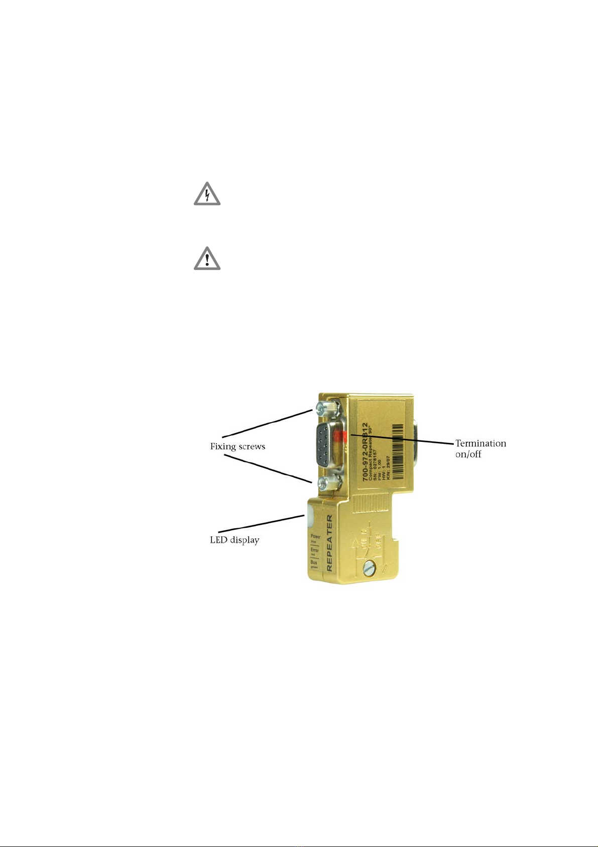
3.2 The LED display and its meaning
The front of the housing of the PROFIBUS Compact Repeater
contains a small white surface (see Fig. on Page 8). Behind this
white surface, you will find three LEDs that show you the
operating status of the PROFIBUS Compact Repeater and the
connected PROFIBUS Segment 2.
Meanings:
Color Flashing
/continuous
Meaning
Flashing Repeater is detecting the baudrateBlue
Continuous Baudrate has been detected
Green Flashing or
continuous
Data exchange is in progress on Segment
2
Red Flashing or
continuous
Repeater finds one or more errors on
Segment 2
PROFIBUS Compact Repeater 9