manuals.online logo
Brands
  1. Home
  2. •
  3. Brands
  4. •
  5. Giacomini
  6. •
  7. Repeater
  8. •
  9. Giacomini GE552Y053 User manual

Giacomini GE552Y053 User manual

9
A
B
A. Cable compartment lid
B. "ON" LED light
1.OVERVIEW
2.Connections/buttons/led lights
USB CONNECTION CONNECTION AT GE552Y058
Before connecting anything, switch the power off, complete the cabling, close the lid and
power the device on.
TROUBLESHOOTING
1) The device does not start:
2) The blue LED light does not stop flashing:
3) Not all the meters are revealed:
3.WALL FASTENING AND CABLE PASS
Temperature range:
Ingress Protection:
Protection Class:
Fastening:
Dimensions:
Power supply:
Consumption:
Radio Frequency:
W. M-Bus Mode:
Max distance between
two RPT:
7.TECHNICAL DATA
1
2
3
+55°C
-20°C
GE552Y053_QSG_2.4_en
Giacomini reserves the right to make changes to this product without any notice
- in case of network power supply, check that the power is on
- in case you are using a USB port, check the USB cable quality and that the PC is enabled
to handle 500 mA of electrical power
- check that the meters that were not revealed are not too distant from GE552Y053 or that
the signal is not disturbed by thick concrete or metal walls
- check that the devices are on the list loaded in GE552Y053 or that the W. M-Bus devices
list receivable from GE552Y053 is not blocked
- warning: some W.M-Bus devices transmit periodically (within hours)
- check that the MESH network is not interrupted using GE552Y058 web interface or GE552Y056 sw
- Receiver and radio repeater for W. M-Bus devices (EN13757-4)
- Remarkable radio coverage due to multi-hop network
architecture (MESH)
- Manages up to 500 meters
- Last acquired data stored in a non-volatile memory
- Easy installation with software setup
- Simple and elegant design
- 100..240Vac power or via USB
- "Wall mounting" like installation
- USB interface for local data reading
- Optional WEB interface to match to GE552Y058
12
1 - Power input 100..240Vac (with clips)
2 - Multifunction button
3 - Multifunction button
4 - Reset button
5 - USB port
34
6 - MESH network TX-RX LED
7 - Wireless M-Bus network TX-RX LED
8 - Signal/reception level LED
9 - State LED
5
67
8
GE552Y053 repeater devices are provided with a MESH- ID=1 and channel 13, make sure that
all the repeaters and/or GE552Y058 have the same MESH network ID and radio channel
through GE552Y056
Operative: -20°C ... +55°C
Storage: -25°C ... +85°C
IP 40 (EN60529)
II
wall clipped
LxHxP 160x160x35mm
100..240Vac 50/60Hz
USB (5Vdc, 500mA) for commissioning
4.5W
868MHz - Max transmission power: 27dBm
S / T / C+T / S & C+T
- check that the device GE552Y058 is on and that the antenna is connected and in good position
(avoid placing it in switchboards or shielded environments)
- 1 blink "RAM memory error", 2 blinks "W.M-Bus radio module error",
3 blinks "MESH radio module error", 4 blinks "FLASH memory error", 5 blinks "Real Time Clock error"
- If turning offand restarting the GE552Y053, the error does not reset, the hardware
must be replaced.
- check that GE552Y053 is at least 5 metres distant from GE552Y058 and from other GE552Y053
- check that the ID and the MESH network channel are correct using GE552Y056 sw and are the
same ones used by GE552Y058
1 - upper hole
2 - lowe pre-hole
3 - cable pass pre-hole
4 - power supply connection
6. REPEATER NETWORK CONFIGURATION
1. Power on GE552Y058, connect to web interface and start antenna and device scan following
the user’s manual
2. Power on the first device GE552Y053 to be installed and move it away to a minimum distance
of 5 metres from GE552Y058
3. Fixed blue GE552Y053 LED shows the connection to the MESH network
4. Once connected, it shows the MESH radio signal quality to the gateway, by turning on the green
front LED, 1 – insufficient reception, 2 – sufficient, 3- good, 4 – excellent
5. Put GE552Y053 in a place where the reception signal is >=2 and of all the W. M-Bus
devices you expect to receive with this antenna is satisfactory
6. Check through GE552Y058 web interface or through GE552Y056 software and a PC connected to the
antenna by USB that W. M-Bus devices, that you want to receive, reach the GE552Y053
7. Fasten the GE552Y053 and proceed with powering a second repeater keeping at least 5 metres
away from both the GE552Y053 and GE552Y058
8. Once connected, it shows the MESH radio signal quality to the gateway, by turning on the front LED,
so proceed as for the first GE552Y053
2 x Anchor 5x25
2 x Screws 5x30
2 x Glands
1 x GE552Y053
4.PACKAGE CONTENT
N
Power
supply
connection
GE552Y053 - QuickStart Guide
Wireless M-Bus 868 MHz REPEATER
DOWNLOAD DOCUMENTATION: https://giacomini.com/en/products/ge552-w
2 x Screw 2,2x9,5
1 x clamp headband
USB
Mini USB
GE552Y058
MIN 5 m
MIN 5 m MIN 5 m
a) The scanning phase is 12 hours. You can modify its duration through GE552Y058
b) You can have various independent GE552Y053 networks in the same building , in that case,
you need to have different ID or channel for each GE552Y056 group and the relative
GE552Y058.
You can modify these parameters through GE552Y056 software installed on a pc and connected via
USB to GE552Y053, see user’s manual for details.
c) In case the receiver receives more than 500 W. M-Bus devices or it receives devices belonging
to other plants, it might be necessary to make it selective. Therefore, you can load a list of W. M-Bus
devices marked by their serial number through GE552Y056 software.
In this way, the repeater will receive the data exclusively from the listed devices.
d) The USB / Mini USB cable is not included and is not present in the package
5.POSITIONING AND OPERATING DISTANCES
MAX 25 m MAX 25 m
GE552Y058
GE552Y053
FLOOR 1
FLOOR 0
MAX 15 m
GE552Y053
FASTENING
WALL
WALL
CEILING
MIN
20 cm
MIN
20 cm
1) Fix the GE552Y053 repeater on fastening wall at a minimum
distance of 20 cm from the ceiling and from the adjacent wall.
2) The maximum operating distance between the devices
installed on the same floor is 25 meters, with no major
obstacles such as reinforced concrete or metal walls, columns
or beams or other metal structures.
3) The maximum operating distance between the devices
installed on different floors is 15 meters.
MIN 5 m
GE552Y053
MIN 5 m
GE552Y053
MAX 25 m
MAX 15 m
Manufactured by GIACOMINI SPA - Via per Alzo 39 - 28017 San Maurizio d'Opaglio (NO) - Italy
For details on the configuration of the GE552Y053 using the buttons, see the back of this
document, in the dedicated section.
L
max 2x1,5 mm2
o 6 mm
4
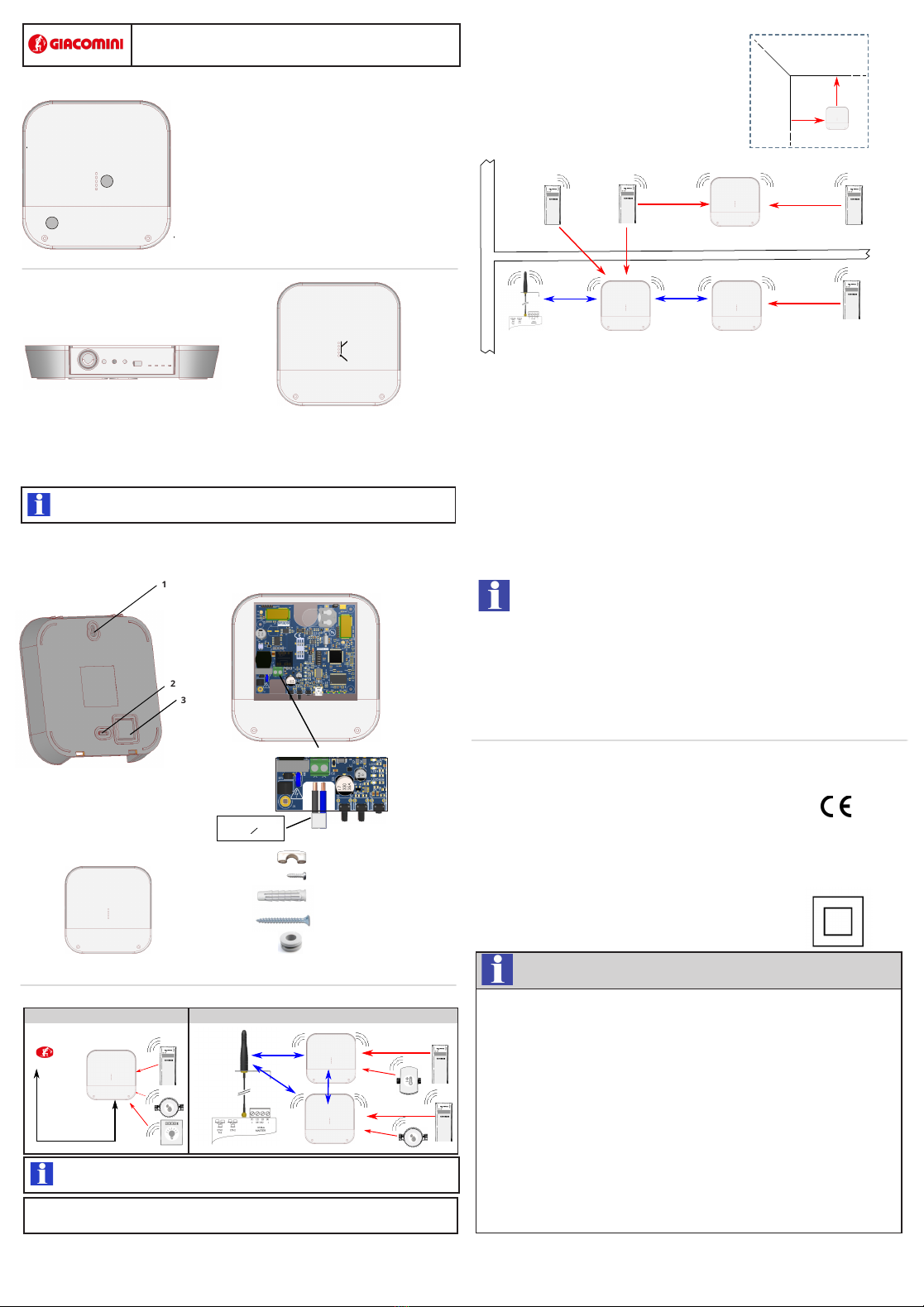
SPECIAL CASES OF USE
The following image shows an installation in which, or for different properties reasons , or for number of
devices to be controlled exceeds 500 (Max 500 for each GE552Y058), it is necessary to create four
different networks of GE552Y053 Repeaters.
Obviously the following is valid also in cases where there are 2, 3, 5 or a higher number of Repeaters
networks.
In order to avoid interferences between the various systems, assign to each GE552Y058 a different Mesh
network ID. The setting is done on GE552Y058 through its web interface; Settings / Wireless Devices /
Wireless Setup / Setup Mesh Network.
The same Mesh network ID setting must be carried out also on all Repeaters that are part of the
network of the GE552Y058 which they have to communicate with.
For this procedure it is necessary to connect a PC to the Repeater to be configured (via USB cable).
Use the GE552Y056 software (downloadable from the download section of it.giacomini.com and follow
the instructions in the manual.
SETTING OF MESH NETWORK ID
Note: It is recommended not to change the Mesh Network Channel (default = 13 both on GE552Y058
and on Repeaters), because the change may involve the transmission power of the devices.
LOADING ON REPEATERS OF A W. M-Bus DEVICES LIST IN THE PLANT
(ONLY ON REPEATERS WITH FIRMWARE VERSION FWRPT1_V1R20.hex ONWARDS)
Referring to the same image of the previous installation, the various Repeaters receive W. M-Bus signal
from their plant devices but they can also receive the signal from devices of adjacent plants.
If one or more Repeaters receive the signal from more than 500 devices (Max 500 for each repeater),
REPEATERS FIRMWARE UPGRADE
You should always check the possible release of the latest firmware available version of the Repeaters,
compared to the one installed on the devices in the production phase.
For this procedure it is necessary to connect a PC to the repeater to be configured (via cable
USB). Use the GE552Y056 software (downloadable from the download section of it.giacomini.com and
follow the instructions in the manual.
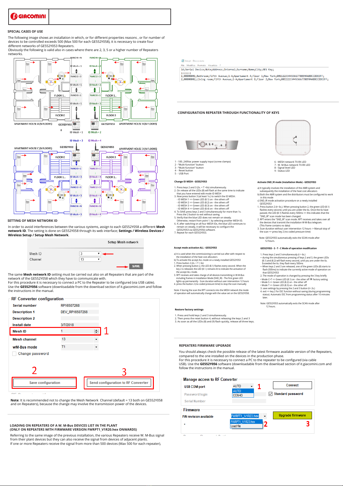
CONFIGURATION REPEATER THROUGH FUNCTIONALITY OF KEYS
Change ID MESH - GE552Y053
1. Press keys 2 and 3 (2s. < T <6s) simultaneously.
2. On release all the LEDs (8) will flash at the same time to indicate
that you have entered edit mode ID MESH
3. Now press button 3 (at least 1s.) to switch the ID MESH.
- ID MESH 1 => Green LED (8.1) on - the others off
- ID MESH 2 => Green LED (8.2) on - the others off
- ID MESH 3 => Green LED (8.3) on - the others off
- ID MESH 4 => Green LED (8.4) on - the others off
4. To SAVE press keys 2 and 3 simultaneously for more than 1s.
Press the 2 button to exit without saving.
5. Verify that the blue LED does not remain on steady.
Otherwise, restart from point 1. by selecting another MESH ID.
6. If, after switching on all four MESH IDs, the blue LED continues to
remain on steady, it will be necessary to configure the
GE552Y053 via GE552Y056 software.
7. Repeat for each GE552Y053.
Activate SND_IR mode (Installation Mode) - GE552Y053
a) It typically involves the installation of the AMR system and
subsequently the installation of the heat cost allocators
b) Both the AMR system and the distributors must be configured to work
in this mode
c) SND_IR mode activation procedure on a newly installed
GE552Y053
1. Press button 2 (t> 6s.). When pressing button 2, the green LED (8.1)
flashes every second, until you are under the 6s. Once the 6s have
passed, the LED (8.1) flashes every 500ms => this indicates that the
"SND_IR" scan mode has been changed.
2. RPT enters the "SND_IR" scan mode. RPT receives and takes over all
the devices that transmit the installation W-M-Bus telegram.
(This frame contains no data)
3. Scan duration without user intervention 12 hours -> Manual stop of
the scan => press key 2 (no coded pressure time)
Note: GE552Y053 automatically exits the SCAN mode after
12 hours.
Accept mode activation ALL - GE552Y053
a) It is used when the commissioning is carried out after with respect to
the installation of the heat cost allocators
b) To activate the accept ALL mode on a newly installed GE552Y053
1. Press button 2 (2s. < T < 6s)
2. When pressing button 2, the LED (8.1) flashes every second. When the
key 2 is released, the LED (8.1.) remains lit to indicate the activation of
the accept ALL mode.
3. RPT receives and takes charge of all devices transmitting in W.M-Bus
including frames in Installation Mode (SND_IR) - The first green LED
lights up permanently - Scan duration without user intervention 12 hours
4. press the button 2 (no coded pressure time) to stop the scan manually
Note: if during the scan the RPT connects into the MESH network the mode
of operation will automatically change with the value set on the GE552Y058.
GE552Y053 - S - T - C Mode of operation modification
1. Press keys 2 and 3 simultaneously (t > 6s.)
─during the simultaneous pressing of keys 2 and 3, the green LEDs
(8.1) and (8.2) will flash every second, until you are under the 6s.
Exceeded the 6s. they flash every 500ms
─When keys 2 and 3 are released, one of the green LEDs (8) starts to
flash (500ms) to indicate the currently active mode of operation on
that GE552Y053
2. The mode of operation is changed by pressing the 3 key briefly
• Mode C+T => Green LED (8.1) on - the other offFactory setting
• Mode S => Green LED (8.2) on - the other off
• Mode T => Green LED (8.3) on - the other off
3. save settings by pressing the 2 and 3 button (t> 2s.)
4. exit => key 2 for ESC function without saving (during programming
status). Automatic ESC from programming status after 10 minutes
later.
Note: GE552Y053 automatically exits the SCAN mode after
12 hours.
Restore factory settings
1. Press and hold keys 2 and 3 simultaneously.
2. Then press the reset button 4, without releasing the keys 2 and 3
3. As soon as all the LEDs (8) and (9) flash quickly, release all three keys.
9
12
1 - 100..240Vac power supply input (screw clamps)
2 - “Multi-function” button
3 - “Multi-function” button
4 - Reset button
5 - USB Port
34
6 - MESH network TX-RX LED
7 - W. M-Bus network TX-RX LED
8 - Signal level LED
9 - Status LED
5
67
8
GE552Y053_QSG_2.5_en
Giacomini reserves the right to make changes to this product without any notice
GE552Y053 - Setup Repeater
Wireless M-Bus 868 MHz REPEATER
DOWNLOAD DOCUMENTATION: https://giacomini.com/en/products/ge552-w
those exceeding 500 are ignored, and may in fact belong to the plant to be checked.
In this case it is necessary to charge, in the same Repeater, a file with a list of devices that are part of
its plant (Maximum 500); after uploading the file, the signal of the devices that are not included in the list
is ignored by the Repeater.
The file, whose name must be list.rpt, must be a CSV file with a format such as the one shown in the
following figure.
For this procedure it is necessary to connect a PC to the Repeater to be configured (via USB cable).
Use the GE552Y056 software and follow the instructions in the manual.
Manufactured by GIACOMINI SPA - Via per Alzo 39 - 28017 San Maurizio d'Opaglio (NO) - Italy

Other manuals for GE552Y053

1

Other Giacomini Repeater manuals

Giacomini KLIMAdomotic TRV KE410 User manual

Giacomini

Giacomini KLIMAdomotic TRV KE410 User manual

Giacomini GE552Y053 User manual

Giacomini

Giacomini GE552Y053 User manual

Giacomini KE410 User manual

Giacomini

Giacomini KE410 User manual

Popular Repeater manuals by other brands

Samson TROVIS 5400 Mounting and operating instructions

Samson

Samson TROVIS 5400 Mounting and operating instructions

Kenwood NEXEDGE NXR-710 Service manual

Kenwood

Kenwood NEXEDGE NXR-710 Service manual

Konig KN-HDMIREP15 user manual

Konig

Konig KN-HDMIREP15 user manual

Vonets VRP300-PLUS Quick setting guide

Vonets

Vonets VRP300-PLUS Quick setting guide

Rebel KOM1031 owner's manual

Rebel

Rebel KOM1031 owner's manual

YOKOGAWA JUXTA F Series user manual

YOKOGAWA

YOKOGAWA JUXTA F Series user manual

GMI D6031S instruction manual

GMI

GMI D6031S instruction manual

LevelOne POT-0100 manual

LevelOne

LevelOne POT-0100 manual

ICP DAS USA ZB-2510 user manual

ICP DAS USA

ICP DAS USA ZB-2510 user manual

Aqua-Marina BLUEDRIVE X user guide

Aqua-Marina

Aqua-Marina BLUEDRIVE X user guide

Cabletron Systems FDDI Repeater user guide

Cabletron Systems

Cabletron Systems FDDI Repeater user guide

BBV Starcard manual

BBV

BBV Starcard manual

Nortek Security & Control 2GIG-RPTR1-345 installation instructions

Nortek Security & Control

Nortek Security & Control 2GIG-RPTR1-345 installation instructions

Vonets VRP150 Quick setting guide

Vonets

Vonets VRP150 Quick setting guide

Fritz! 1200 AX quick start guide

Fritz!

Fritz! 1200 AX quick start guide

Andrew MRx18/x18 user manual

Andrew

Andrew MRx18/x18 user manual

Avenview HBT-C6POE-EX user guide

Avenview

Avenview HBT-C6POE-EX user guide

Gira 5110 00 Product documentation

Gira

Gira 5110 00 Product documentation

manuals.online logo
manuals.online logoBrands
  • About & Mission
  • Contact us
  • Privacy Policy
  • Terms and Conditions

Copyright 2025 Manuals.Online. All Rights Reserved.