Hely&Weber Knapp User manual

Rev D 7/13
Knapp™ Hinged Knee Orthosis Range of Motion 16in
See Hinge Stop Application Instructions on Back
1. Center brace on back of leg. 2. Pull and fasten upper and lower flaps.
3. Pull lower straps through D-Rings and secure. 4. Pull upper straps through D-Rings and secure.
5. Finished application.
5658ROM
1. 2.
3. 4.
5.
Warnings and Instructions: Review carefully, proper application is required
YWarning: This device will not prevent or eliminate risk of injury. Do Not Overtighten. If swelling, pain, skin
irritation, or an unusual reaction occurs, discontinue use immediately and consult your medical professional.
This device should not be worn by persons with known allergies to neoprene.
Care: Hand wash using mild soap. Rinse thoroughly. Air dry only. Do not tumble dry.
© 2017 Weber Orthopedics Inc.
DBA Hely & Weber all rights reserved
1185 E Main St., Santa Paula, California 93060
California: 800-221-5465, National: 800-654-3241
International: 805-525-4244, fax: 805-933-2348
U.S. fax: 800-559-5975, www.hely-weber.com
C
P
MDSS GmbH, Schiffgraben 41
30175 Hannover, Germany
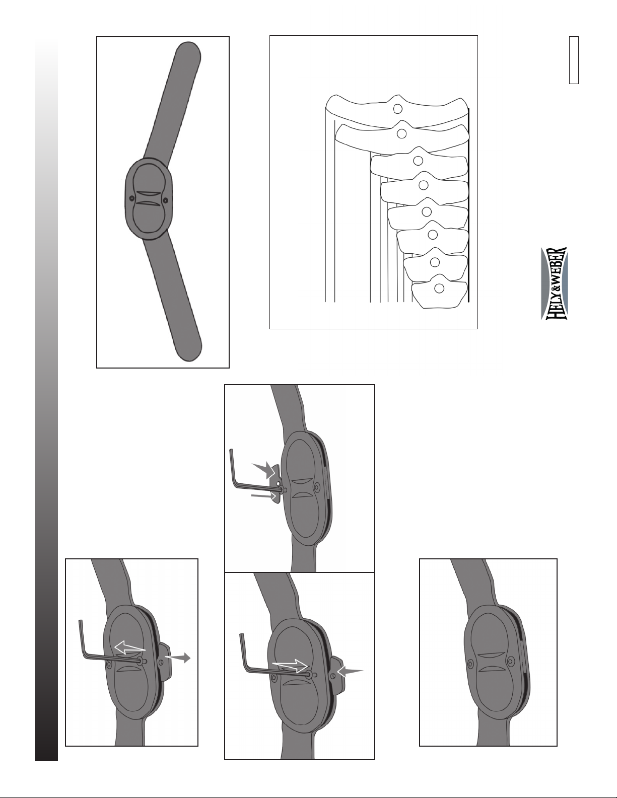
Range of Motion Hinge Stop Application
© 2017 Weber Orthopedics Inc.
DBA Hely & Weber all rights reserved
1185 E Main St., Santa Paula, California 93060
California: 800-221-5465, National: 800-654-3241
International: 805-525-4244, fax: 805-933-2348
U.S. fax: 800-559-5975, www.hely-weber.com
C
P
MDSS GmbH, Schiffgraben 41
30175 Hannover, Germany
Rev B 4/16
1. Use the included hex wrench to remove the existing
hinge stops by removing the screws.
1.
2. Choose the hinge stops with the desired degrees of extension and exion. Install the extension stop on the
extension stop side of the hinge, and the exion stop on the exion stop side of the hinge. Tighten the screws so
they are secure but not tight. If the hinges do not move freely loosen the screws.
2.
3. Completed application.
Both medial and lateral hinges must be set to the same extension and exion.
3.
E0 F100
E10 F90
E20 F80
E30 F70
E40 F60
E50 F50
F10
F0
HINGE STOP FINDER
Hinge stops shown below are included for Flexion (F) and Extension (E)
Place hinge stop on chart to verify size
Each stop has two numbers on the front for the degree of flexion (F) or the degree of extension (E)
based on which side of the hinge the stop is used.
EXTENSION STOP SIDE
FLEXION STOP SIDE
Table of contents
Other Hely&Weber Personal Care Product manuals

Popular Personal Care Product manuals by other brands


HOFFEN
HOFFEN SS-0137 instruction manual

Knightsbridge
Knightsbridge RCTRGB Installation & maintenance manual

Medex
Medex B07 user guide

Dinar
Dinar AirStyle AIRBRUSH quick start guide

Industrial Lighting
Industrial Lighting Andromeda S Instructions for use

Eurofase Lighting
Eurofase Lighting 33824-017 instruction manual