manuals.online logo
Brands
  1. Home
  2. •
  3. Brands
  4. •
  5. Henderson
  6. •
  7. Door Lock
  8. •
  9. Henderson TWINBOLT User manual

Henderson TWINBOLT User manual

1
TWINBOLT
Fitting Instructions
KIT AND DOOR SPECIFICATION
Product
Short Code
For Use With
Min. Door
Thickness
Max. Door
Thickness
Max. Door
Height
TB/SF
Securefold 50kg and 100kg - Non Mortice
56mm
68mm
3300mm
TB/SFM
Securefold 50kg and 100kg - Mortice
56mm
68mm
3300mm
TB/SF150
Securefold 150kg - Non Mortice
56mm
68mm
4000mm
TB/SFBR
Securefold Bottom Rolling 80kg - Non Mortice
56mm
68mm
3000mm
TB/SFMBR
Securefold Bottom Rolling 80kg - Mortice
56mm
68mm
3000mm
2 x Floor Keep
(x 1 in SFBR Kits)
TBCS** Cover Strip
(Available in Black, Brown or White)
KIT CONTENTS
ACCESSORIES
2 x Keep Plates
2 x Shoot Bolt
Block
1 x Cover
Plate
1 x Long Lock Rod
1 x Short Lock Rod
1 x Lock Box
Screw Pack Contents
4 x Ø4.5x30 wood screw
2 x 1 ¾”x8g wood screws
2 x M4x9 countersunk head screws
4 x M4x12 countersunk head screws
2 x lock box to rod connectors
TWINHAN/S Twinbolt Handle Kit
(Including handle, cylinder cover plate and screws)
2
TOOLS REQUIRED
Drill & Drill Bit Size
Ø3.0 & Ø4.1
(for adjustment only)
Tape Measure
Pencil
(for adjustment only)
Hacksaw
(for adjustment only)
Posi Drive
Screwdriver
Router
3
MORTICE OUTWARD OPENING ROUTING DETAIL
Shoot Bolt Block
Lock Rod
Lock Box & Cover Plate
Euro Cylinder & Escutcheon
Handle
4
Lock Box & Cover Plate
Shoot Bolt block
Shoot Bolt block
MORTICE INWARD OPENING ROUTING DETAIL
Shoot Bolt block
Lock Rod
Euro Cylinder & Escutcheon
Handle
Lock Box & Cover Plate
5
NON MORTICE OUTWARD OPENING ROUTING DETAIL
Shoot Bolt Block
Lock Rod
Euro Cylinder & Escutcheon
Handle
Lock Box & Cover Plate
6
NON MORTICE INWARD OPENING ROUTING DETAIL
Shoot Bolt Block
Lock Rod
Lock Box & Cover Plate
Euro Cylinder & Escutcheon
Handle
7
ROUTING DETAIL FOR SECUREFOLD 50 AND 100 KEEP PLATES
ROUTING DETAIL FOR SECUREFOLD 150 KEEP PLATES
ROUTING DETAIL FOR SECUREFOLD BOTTOM ROLLING KEEP PLATES
8
STEP 1: To reduce for specific door size, cut top lock rod only to suit door specific door height
Calculation: Max door height (system specific) –actual door height = lock rod reduction
Max Door Height: SF50 & 100 = 3300mm | SF Bottom Rolling = 3000mm | SF150 = 4000mm
A: Cut the long lock rod to the
required length (see calculation
above).
C. Remove connecting pin –open out
holes to Ø4.1. Introduce
countersink as required
B. Use connecting pin as drill
guide –Drill 2 X Ø3.0
D. Attach connecting pin and secure screws with thread lock
adhesive
E. Follow steps 2 through 7 to insert
hardware into door
M4 x 12
Countersink
Screws
Non Mortice Version
Non Mortice
Version
Mortice
Version
Mortice
Version
STEP BY STEP INSTRUCTIONS
PLEASE NOTE: The following instructions are to suit installation of the euro cylinder lock above the handle (please
see Appendix A, layout A. For installation instructions to have the euro cylinder lock below the handle, please see
Appendix A, layout B.
9
STEP 2:Attach lock rods to lock box –ensure long lock rod is located in threaded end nearest the euro cylinder
Euro Cylinder
End
STEP 3: Rotate lock rods to engage with lock box
10
STEP 4: Insert assembly into routed door edge
STEP 5: Position shoot bolt blocks in both ends
11
STEP 7: Attach cover plate
1 ¾”x8g wood screws
STEP 6: Secure blocks with screws
M4x9 countersunk head screws
12
STEP 9: Fit handle and cylinder plate with suitable fixings
STEP 8: If using the TBCS Routing Cover Strip, please cut to length and insert coloured rubber seal into lock rod
slot
FITTING OF ACCESSORIES
13
P C Henderson Ltd, Durham Road, Bowburn, Co. Durham, DH6 5NG, UK
UK Sales Export Sales
t: +44 (0) 191 377 7345 t: +44 (0) 191 377 7346
e: sales@pchenderson.com e: international@pchenderson.com
w: www.pchenderson.com w: export.pchenderson.com
Appendix A
To fit the system with LAYOUT B set up with the key at the bottom.
Invert the dimensions and exchange the top and bottom lock rods.
Maintain the 1050mm to the centre of the handle.
664265
LVL5
August 2019
1050
1050
LAYOUT A
LAYOUT B

Popular Door Lock manuals by other brands
Relcross Door Controls KEYLEX 700 (FP) Installation
Relcross Door Controls

Relcross Door Controls KEYLEX 700 (FP) Installation

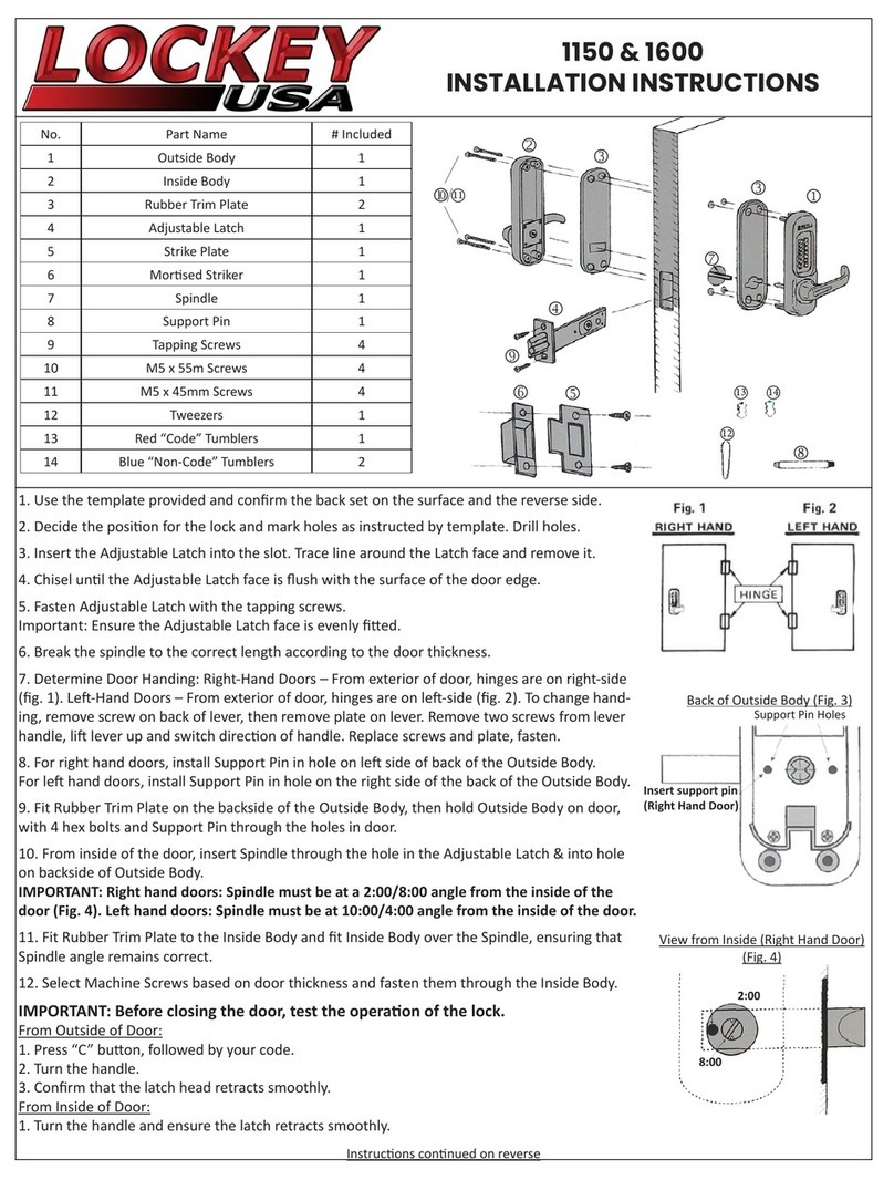
LOCKEY USA 1150 installation instructions
LOCKEY USA

LOCKEY USA 1150 installation instructions

CISA SIKUREXIT 43295 Series instruction sheet

CISA

CISA SIKUREXIT 43295 Series instruction sheet

Ingersoll-Rand Schlage F54 installation instructions
Ingersoll-Rand

Ingersoll-Rand Schlage F54 installation instructions

Conrad Electronic 751549 operating instructions
Conrad Electronic

Conrad Electronic 751549 operating instructions

Assa Abloy Yale Doorman installation guide
Assa Abloy

Assa Abloy Yale Doorman installation guide

Yale Lockmaster AutoEngage Installation and Adjustment guide

Yale

Yale Lockmaster AutoEngage Installation and Adjustment guide

Dorma MUNDUS PREMIUM US 10 Mounting instruction

Dorma

Dorma MUNDUS PREMIUM US 10 Mounting instruction

Assa Abloy effeff 827A-IP Mounting instructions

Assa Abloy

Assa Abloy effeff 827A-IP Mounting instructions

ArrowVision Shepherd 210 installation manual
ArrowVision

ArrowVision Shepherd 210 installation manual

Lockly DEADBOLT SECURE PLUS user manual

Lockly

Lockly DEADBOLT SECURE PLUS user manual

Allegion Schlage F Series installation instructions

Allegion

Allegion Schlage F Series installation instructions

SATIE EF150ENC CA installation instructions

SATIE

SATIE EF150ENC CA installation instructions

Schlage Ease S2 quick start guide

Schlage

Schlage Ease S2 quick start guide

hentech MS5000Q instructions

hentech

hentech MS5000Q instructions

Detex ADVANTEX 62 Series installation instructions

Detex

Detex ADVANTEX 62 Series installation instructions

ZKTeco L5000 user manual

ZKTeco

ZKTeco L5000 user manual

Assa Abloy CYE321 Installation

Assa Abloy

Assa Abloy CYE321 Installation

manuals.online logo
manuals.online logoBrands
  • About & Mission
  • Contact us
  • Privacy Policy
  • Terms and Conditions

Copyright 2025 Manuals.Online. All Rights Reserved.