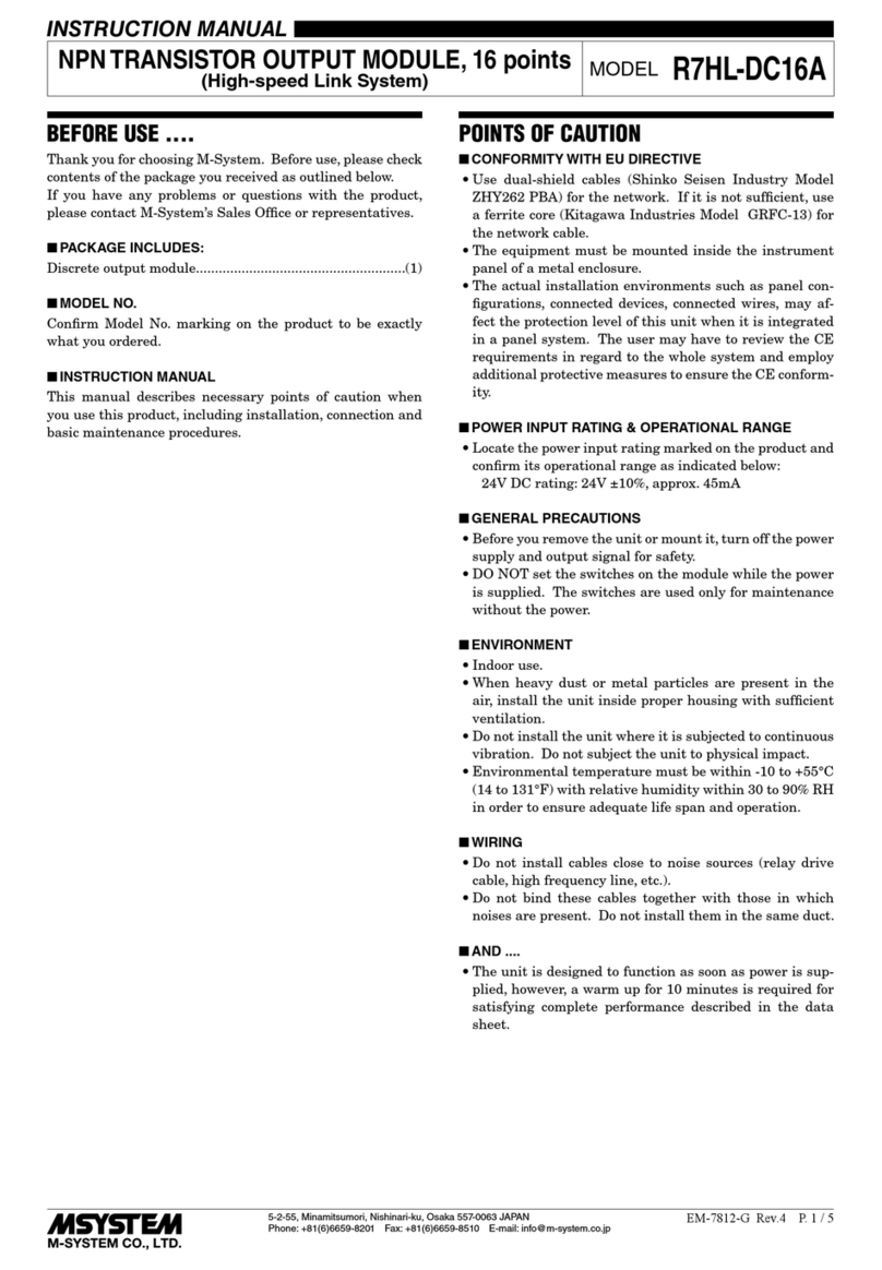
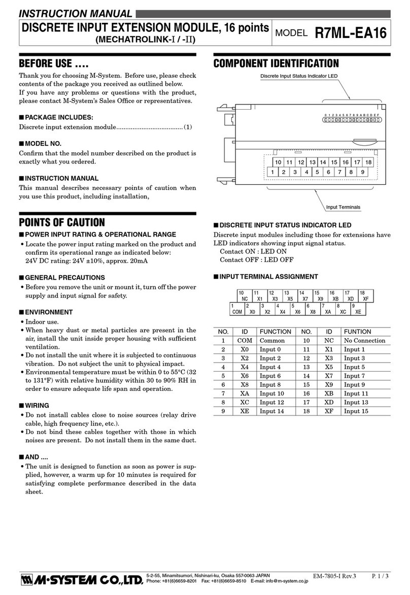
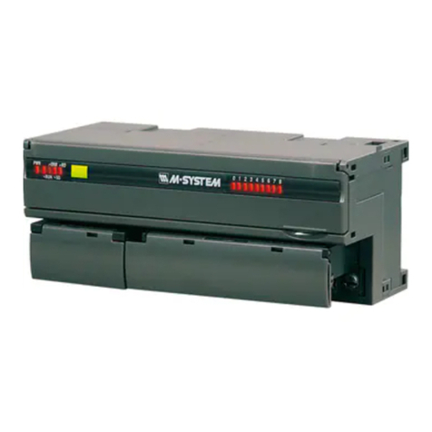
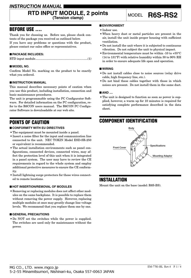
manuals.online logo
Brands
  1. Home
  2. •
  3. Brands
  4. •
  5. M-system
  6. •
  7. Control Unit
  8. •
  9. M-system R3-PS3 User manual

M-system R3-PS3 User manual

R3-PS3
P. 1 / 2EM-8358 Rev.5
5-2-55, Minamitsumori, Nishinari-ku, Osaka 557-0063 JAPAN
Phone: +81(6)6659-8201 Fax: +81(6)6659-8510 E-mail: info@m-system.co.jp
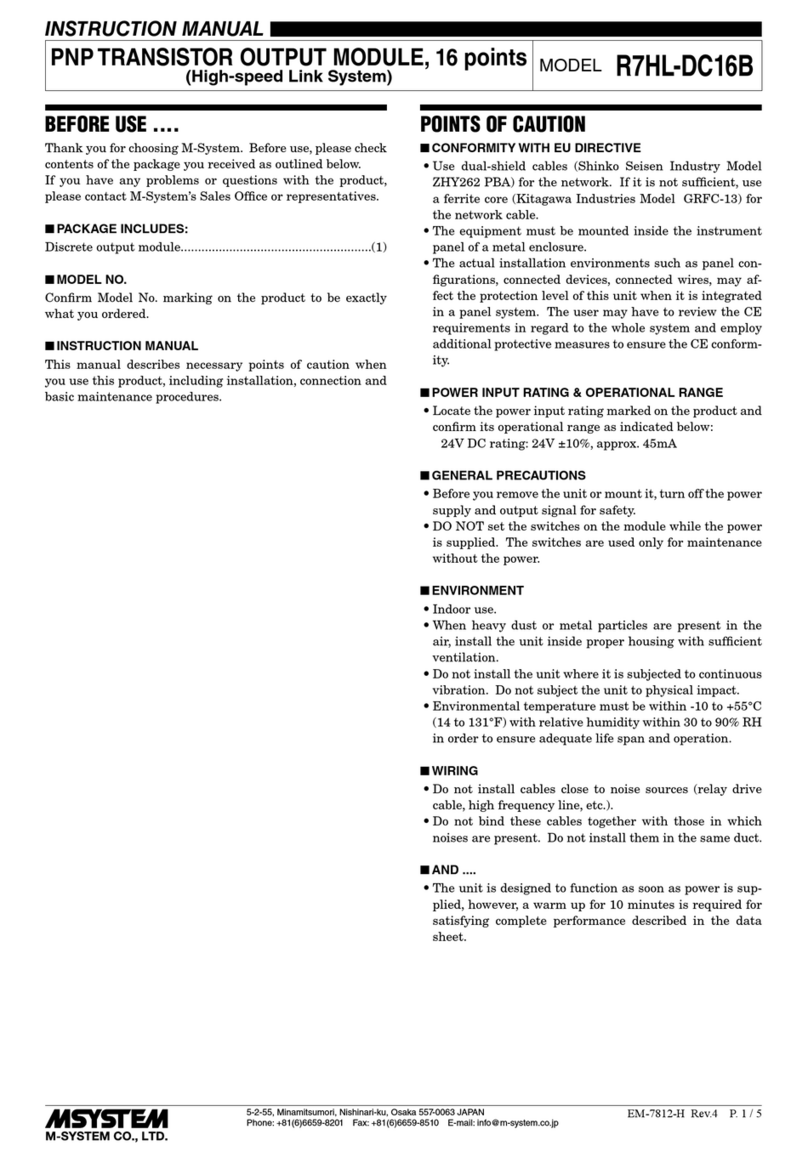
POWER SUPPLY MODULE MODEL R3-PS3
INSTRUCTION MANUAL
BEFORE USE ....
Thank you for choosing M-System. Before use, please check
contents of the package you received as outlined below.
If you have any problems or questions with the product,
please contact M-System’s Sales Office or representatives.
■PACKAGE INCLUDES:
Power supply module ................................................... (1)
■MODEL NO.
Confirm Model No. marking on the product to be exactly
what you ordered.
■INSTRUCTION MANUAL
This manual describes necessary points of caution when
you use this product, including installation, connection and
basic maintenance procedures.
POINTS OF CAUTION
■CONFORMITY WITH EU DIRECTIVES
•This equipment is suitable for use in Installation Cat-
egory II and Polution Degree 2. Reinforced insulation
(internal power to power input to: 300 V) and basic insu-
lation (internal power to RUN contact output: 300 V) are
maintained. Prior to installation, check that the insula-
tion class of this unit satisfies the system requirements.
•Altitudeupto2000meters
•The equipment must be mounted inside the instrument
panel of a metal enclosure.
•The equipment must be installed such that appropriate
clearance and creepage distances are maintained to con-
form to CE requirements. Failure to observe these re-
quirements may invalidate the CE conformance.
• The actual installation environments such as panel
configurations,connected devices, connected wires, may
affect the protection level of this unit when it is integrated
in a panel system. The user may have to review the CE re-
quirements in regard to the whole system and employ ad-
ditional protective measures to ensure the CE conformity.
■POWER INPUT RATING & OPERATIONAL RANGE
•
Locate the power input rating marked on the product and con-
firm its operational range as indicated below:
 85–132VACrating:85–132V,47–66Hz,approx.100VA
100–120VACrating:85–132V,47–66Hz,approx.100VA
170–264VACrating:170–264V,47–66Hz,approx.100VA
200–270VACrating:170–264V,47–66Hz,approx.100VA
24VDCrating:24V±10%,approx.50Wor2.0Aat24V
 110VDCrating:85–150V,approx.50Wor440mAat110V
■GENERAL PRECAUTIONS
•Beforeyouremovetheunitfromitsbaseormountit,turn
off the power supply for safety.
■ENVIRONMENT
•Indooruse
•Whenheavydustormetalparticlesarepresentintheair,
install the unit inside proper housing with sufficient ven-
tilation.
•Donotinstalltheunitwhereitissubjectedtocontinuous
vibration.Donotsubjecttheunittophysicalimpact.
•Environmentaltemperaturemustbewithin-10to+55°C
(14to131°F)withrelativehumiditywithin30to90%RH
in order to ensure adequate life span and operation.
■WIRING
•Do not install cables close to noise sources (relay drive
cable, high frequency line, etc.).
•Do not bind these cables together with those in which
noises are present. Do not install them in the same duct.
■AND ....
•Theunitisdesignedtofunctionassoonaspowerissup-
plied, however, a warm up for 10 minutes is required for
satisfying complete performance described in the data
sheet.
INSTALLATION
Use the Installation Base (model: R3-BSx).
For heat dissipation, install the power supply module into
the rightmost slot or leftmost slot. For redundant power
system, install two modules in series into the rightmost slot
or leftmost slot. If there is no problem, the rightmost slot is
recommended.
In case of redundant power system use, be sure to install
two same current capacity power supply modules (model:
R3-PS3) in series. The combination of different current ca-
pacity power supply module or interface module with power
supply is not available.
R3-PS3
P. 2 / 2EM-8358 Rev.5
5-2-55, Minamitsumori, Nishinari-ku, Osaka 557-0063 JAPAN
Phone: +81(6)6659-8201 Fax: +81(6)6659-8510 E-mail: info@m-system.co.jp
EXTERNAL DIMENSIONS unit: mm (inch)
1
2
3
4
5
6
130 (5.12)
55 (2.17)
POSITIONING
GUIDE
TERMINAL
COVER
6–M3
SCREW
6.2
(.24)
109 (4.29)
90 (3.54)19 (.75)
■ STANDARD TYPE
■ OPTION /B
TERMINAL CONNECTIONS
Connect the unit as in the diagram below.
WIRING INSTRUCTIONS
■SCREW TERMINAL
Torque: 0.5 N·m
■SOLDERLESS TERMINAL mm (inch)
Refer to the drawing below for recommended ring tongue
terminalsize.Spadetonguetypeisalsoapplicable.Solder-
less terminals with insulation sleeve do not fit.
Applicablewiresize:0.3to0.5mm2
Recommended manufacturer: Japan Solderless Terminal
MFG. Co., Ltd., Nichifu Co., Ltd.
3.2 (.13) dia.
4 min.
(.16)
12 (.47) max.
6 max.
(.24)
3 (.12) max.
INTERNAL
POWER
2
3
6
U (+)
V (–)
*FG
POWER INPUT
BUS CONNECTOR
1
4
RUN +
RUN –
RUN CONTACT
OUTPUT
*In order to improve EMC performance, bond the FG terminal to the ground.
Caution. This terminal is NOT a protective conductor terminal.

Other M-system Control Unit manuals

M-system R7M-CT4E User manual

M-system

M-system R7M-CT4E User manual

M-system R3-PA8 User manual

M-system

M-system R3-PA8 User manual

M-system R7C-RR4 User manual

M-system

M-system R7C-RR4 User manual

M-system R7M-DC16B User manual

M-system

M-system R7M-DC16B User manual

M-system R8-NECT1 User manual

M-system

M-system R8-NECT1 User manual

M-system R3-NF1 User manual

M-system

M-system R3-NF1 User manual

M-system R7E-DA16 User manual

M-system

M-system R7E-DA16 User manual

M-system R3-SV8C User manual

M-system

M-system R3-SV8C User manual

M-system R7ML-YV2 User manual

M-system

M-system R7ML-YV2 User manual

M-system R3Y-PA16 User manual

M-system

M-system R3Y-PA16 User manual

M-system R7C-EC8B User manual

M-system

M-system R7C-EC8B User manual

M-system R3-PD16 User manual

M-system

M-system R3-PD16 User manual

M-system R1D-GH2 User manual

M-system

M-system R1D-GH2 User manual

M-system R7HL-DAC15E User manual

M-system

M-system R7HL-DAC15E User manual

M-system Devicenet R7F4HD-DAC32D User manual

M-system

M-system Devicenet R7F4HD-DAC32D User manual

M-system R5-NM1 User manual

M-system

M-system R5-NM1 User manual

M-system R7M-EC8C User manual

M-system

M-system R7M-EC8C User manual

M-system M6DXF1 User manual

M-system

M-system M6DXF1 User manual

M-system R7G4FML3-6-DC16A User manual

M-system

M-system R7G4FML3-6-DC16A User manual

M-system R7C-EC8B/UL User manual

M-system

M-system R7C-EC8B/UL User manual

M-system R7D-EC8A User manual

M-system

M-system R7D-EC8A User manual

M-system R6S-RS2 User manual

M-system

M-system R6S-RS2 User manual

M-system R3-NE1 User manual

M-system

M-system R3-NE1 User manual

M-system R7ML-YV2-R User manual

M-system

M-system R7ML-YV2-R User manual

Popular Control Unit manuals by other brands

Graco SDM8 Series instructions

Graco

Graco SDM8 Series instructions

EuroLite LCD-4 user manual

EuroLite

EuroLite LCD-4 user manual

Thermia EM3 installation guide

Thermia

Thermia EM3 installation guide

Union Switch & Signal GENISYS II Hardware installation

Union Switch & Signal

Union Switch & Signal GENISYS II Hardware installation

Cycle Stop Valves CSV1A installation instructions

Cycle Stop Valves

Cycle Stop Valves CSV1A installation instructions

Extron electronics AC 102 installation guide

Extron electronics

Extron electronics AC 102 installation guide

Dungs DMV 11 eco Series Operation and assembly instructions

Dungs

Dungs DMV 11 eco Series Operation and assembly instructions

Velocity VL-ZMB installation instructions

Velocity

Velocity VL-ZMB installation instructions

ALM O/A/x2 Operation manual

ALM

ALM O/A/x2 Operation manual

ELEKTRODESIGN Digireg evo.018 user manual

ELEKTRODESIGN

ELEKTRODESIGN Digireg evo.018 user manual

GEM B56 operating instructions

GEM

GEM B56 operating instructions

Xylem SI Analytics TITRATOR TitroLine 7500 KF operating instructions

Xylem

Xylem SI Analytics TITRATOR TitroLine 7500 KF operating instructions

Saluki SMR Series Quick start manual

Saluki

Saluki SMR Series Quick start manual

Toshiba B-EX906-H-QM-R manual

Toshiba

Toshiba B-EX906-H-QM-R manual

Videx 4830 Installation instruction

Videx

Videx 4830 Installation instruction

AMCI PowerFlex 750 Series user manual

AMCI

AMCI PowerFlex 750 Series user manual

SimCom SIM900B EVB user guide

SimCom

SimCom SIM900B EVB user guide

IS5 COMMUNICATIONS RAPTOR Series user guide

IS5 COMMUNICATIONS

IS5 COMMUNICATIONS RAPTOR Series user guide

manuals.online logo
manuals.online logoBrands
  • About & Mission
  • Contact us
  • Privacy Policy
  • Terms and Conditions

Copyright 2025 Manuals.Online. All Rights Reserved.