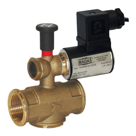
Henkel LOCTITE EQ VA40 CA User manual

EQ VA40 CA Volumetric Valve
2333708
Operating Manual

1
Table of Contents
1Please Observe the Following...................................................................................................2
1.1 Emphasized Sections...........................................................................................................2
1.2 For Your Safety.....................................................................................................................2
1.3 Unpacking and Inspection ..................................................................................................3
1.4 Items supplied ......................................................................................................................3
1.5 Features.................................................................................................................................3
1.6 Usage.....................................................................................................................................3
2Description...................................................................................................................................4
3Specifications ..............................................................................................................................4
4Installation....................................................................................................................................5
5Operation......................................................................................................................................6
6Application Hints.........................................................................................................................7
7Troubleshooting...........................................................................................................................7
8Care and Maintenance ...............................................................................................................8
9Accessories and Spare Parts...................................................................................................13
10 Diagram…………………………………………………………………………………………….13
11 Warranty.....................................................................................................................................14

2
1 Please Observe the Following
1.1 Emphasized Sections
Warning!
Refers to safety regulations and requires safety measures that protect the operator
or other persons from injury or danger to life.
Caution!
Emphasizes what must be done or avoided so that the unit or other property is not
damaged.
Notice:
A notice gives recommendations for better handling of the unit during operation or
adjustment as well as for service activities.
1.2 For Your Safety
For safe and successful operation of the unit, read these instructions
completely. If the instructions are not observed, the manufacturer can assume no
responsibility.
Do not expose the connecting plastic lines to heat, oil, or sharp edges.
Make sure the unit stands stable and secure.
Use only original equipment replacement parts.
Always disconnect the power supply before servicing the unit.
Always disconnect the pneumatic supply before servicing the unit.
Observe general safety regulations for the handling of chemicals such as
Loctite®®adhesives and sealants. Observe the manufacturer’s instructions as stated
in the Safety Data Sheet.
While under warranty, the unit may be repaired only by an authorized Loctite®
service representative.

3
1.3 Unpacking and Inspection
Carefully unpack the Loctite®®EQ VA40 CA Volumetric Valve and examine the items
contained in the carton. Inspect the unit for any damage that might have occurred in
transit. If such damage has occurred, notify the carrier immediately. Claims for
damage must be made by the consignee to the carrier and should be reported to the
manufacturer.
1.4 Items supplied
•Loctite® EQ VA40 CA Volumetric Valve 2333708
•Equipment Manual
•PTFE lined tubing, 6.4mm OD, 2 meters long
•Air Line 4mm OD, blue, 2 meters
•Air Line 4mm OD, yellow, 2 meters
•Needle Sample Kit
1.5 Features
•Volumetric displacement
•Dosing range, 1.5 –6 microliters
•Long Life Seal Design > 1 Million Cycles
•Compact size, 1.5” square x 7.0” long {38 mm square x 178 mm long]
•Stackable at 38mm (1.5 “)
•Cycle rate, 120 /minute
•Adhesive compatibility, Cyanoacrylate [CA]
•Fluid body material: 316 stainless steel
•Quick priming check valve
•Fitting –¼” tube x 1/16 NPT, 316 stainless steel
1.6 Usage
The Loctite® EQ VA40 CA Volumetric Valve is a positive displacement
metering valve which dispenses a precise drop of adhesive with each cycle.
Positive displacement is not influenced by variations in pressure, time,
temperature or adhesive viscosity therefore making it a better choice for drop
applications. The Loctite® EQ VA40 CA Volumetric Valve is specifically
designed to dispense low to medium viscosity Loctite® Cyanoacrylate
Adhesives.

4
2 Description
The Loctite® EQ VA40 CA Volumetric Valve is a positive displacement metering valve
which dispenses a precise drop of adhesive with each cycle. The EQ VA40 is
designed with a flooded chamber and a single check valve that allows for quick
priming and minimizes the need for re-priming. The check valve is a patent pending
design which improves the speed and reliability of priming. The Loctite®EQ VA40 is
specifically designed to dispense drops of Loctite® Cyanoacrylate Adhesive with
precise dosing in the range of 1.5 to 6.0 microliters.
The Loctite® EQ VA40 CA Volumetric Valve dimensions are 38mm [1.5”] square and
an overall length of 17.8 cm [7.0”]. This compact dispense valve is stackable at
19mm centers. The fluid body is made of 316 stainless steel and the actuator is
anodized aluminum. The actuator is a double acting cylinder with an aluminum
piston for long life. The Loctite® EQ VA40 CA Volumetric Valve is capable of
dispense rates up to 2 cycles per second.
3 Specifications
Dimensions (L x Width) 17.2 cm [6.8”] long X 3.8 cm [1.5”] SQ
Total weight: lbs. (Kg) 0.82Kg
Viscosity Range: 1 to 10000cP
Operating Air pressure: 4 to 7 bars [60 -100 Psi]
Operating Product pressure: 2 to 5 bars [30 to 70 Psi]
Fluid Body 316 Stainless Steel
Seal PTFE Diaphragms
Displacement Pin TiN coated
Fluid Inlet Thread 1/16 NPT
Threaded Hole-Mounting M4 x 0.7mm
Center to Center Spacing 38mm (1.5“)

5
4 Installation
The Loctite® EQ VA40 CA Volumetric Valve requires a four-way pneumatic solenoid
valve to actuate the cylinder section. The pneumatic valve must be operated with
clean dry air at 4 to 7 bars of pressure. The 4-way pneumatic solenoid valve has a
normally open port and a normally closed port. Use the supplied 4 mm OD tubing to
connect the air ports to the EQ VA40 Volumetric Valve.
The adhesive is supplied from a pressure reservoir 6.4mm tube x 1/16 NPT fitting
located on the top of the Loctite®EQ VA40 CA Volumetric Valve. Use the supplied
6.4 mm OD tubing, insert the tube into the compression fitting and tighten. Secure
the tubing to the reservoir with a compression fitting which allows the tubing to pass
through the fitting into the adhesive container.
Supply clean, dry, regulated air to the reservoir and set the pressure at 2 bars [30
psi]. For best results use dry nitrogen if available. The reservoir pressure setting is
to ensure adhesive product will flow into the Loctite® EQ VA40 CA Volumetric Valve
at a rate which allows the EQ VA40 to operate at 120 cycles per minute.
Loctite®EQ VA40 CA Volumetric Valve –Annotated Drawing
Product Inlet Fitting
Mounting Hardware
Locking Set
Screw
for Stroke
Stroke Adjuster
Airport - normally
close
Airport –normally
Luer Check Valve
Used for priming
Tip Retainer
Upper Diaphragm Assembly

6
5 Operation
•The Loctite® EQ VA40 CA Volumetric Valve is ready to dispense - control lines are
installed; pressure reservoir is loaded with adhesive and a feed line is attached to
the product inlet fitting. The pneumatic pressure to the controller is set at 4 bars and
the reservoir pressure is set at 2 bars. The system is now ready to setup for drop
dispensing:
1. A dispense tip is inserted onto the Luer Check Valve and secured with the Tip
Retainer Nut.
2. To prime the Loctite® EQ VA40 CA Volumetric Valve rotate the Luer Check Valve
counterclockwise 2 1/4 rotations. When a steady flow of bubble free adhesive is
observed rotate the Luer Check Valve clockwise and tighten. Cycle the Loctite® EQ
VA40 CA Volumetric Valve 5 to 10 actuations and repeat priming. This action will
dislodge air under the diaphragm seals.
3. The drop size is determined by the length of the stroke which the displacement rod
travels into the displacement chamber. The drop decreases as the stroke is
shortened. The stroke is set by loosening the locking set screws and rotating the
stroke adjuster counterclockwise to decrease the stroke.
Maximum Stroke
Stroke Adjuster is Flush
Drop Size ~ 6.0 µl
Minimum Stroke –Rotate stroke
adjuster counterclockwise 2.25
revolutions. Drop Size ~ 1.4 µl
2.25 revolutions
Locking set
screw
Locking set
screw

7
4. The Loctite® EQ VA40 CA Volumetric Valve is ready to dispense. Set actuation rate at
greater than or equal to 0.2 seconds.
5. Cycle the Loctite® EQ VA40 CA Volumetric Valve 5 -10 times and then measure drop
size. Adjust stroke to suit.
6 Application Hints
The Loctite® EQ VA40 is specifically designed to dispense drops of Loctite®
Cyanoacrylate Adhesive. This adhesive is moisture sensitive. Clean dry air must be
used to pressurize adhesive but for best results dry nitrogen is recommended.
Shutdown –Always keep the Loctite® EQ VA40 CA Volumetric Valve full of adhesive.
At the end of the day depressurize the reservoir. The dispense needle will cure and seal
the system. Always install a new dispense tip after all extended shutdown periods.
7 Troubleshooting
Problem
Possible Cause
Correction
No liquid flow
•If pneumatic valve
operating pressure is to
low, the valve will not shift.
•The reservoir pressure may
not be high enough
•Displacement rod may be
in forward position
•The dispense tip may be
clogged.
•Stroke Adjuster maybe out
of range
•Increase air pressure to 60
psi (4 bar) minimum
•Increase pressure to 30 psi
(2 bar)
•Check air lines to ensure
that the normally open
airport is energized
•Replace tip
•Ensure stroke adjuster is
with 2.25 revolutions of
adjustment. (section 5-3)

8
Fluid drools after
the volumetric
valve is cycled,
eventually
stopping.
•This is caused by air
coming from the reservoir
into the fluid body and
pumped out into the Luer
check valve. The air will
expand after the check
valve closes, causing
product to extrude out the
dispense tip until the air
reaches atmospheric
pressure.
•Prime the Loctite® EQ VA40
CA Volumetric Valve by
rotating the Luer Check Valve
counterclockwise 2 1/4
rotations. When a steady
flow of adhesive is observed
rotate the Luer Check Valve
clockwise and tighten.
Liquid drips at a
steady rate after
the valve closes.
•A steady drip can be
caused by excessive
reservoir pressure.
•The Luer Check Valve is
not closing fully due to
particle build up on the ball
and seat.
•Check reservoir pressure to
ensure it is not above 70 psi
(4.8 bar)
•Remove the Luer check
valve body, inspect sealing
surfaces and ball surface.
Clean or replace ball if
contaminated with
particulate.
Liquid flows out
of the drain hole
•Fluid leaking out of the
drain hole indicates a seal
failure.
•Replace seal in accordance
with maintenance
instructions
Difficulty
adjusting the
stroke
•The locking set screw is
screw in place.
•Airlines on actuator are in
wrong position.
•Loosen set screw to adjust
stroke.
•Reverse airlines –bottom
airport is normally open, air
flowing at start up. (section
4)
8 Care and Maintenance
The Loctite® EQ VA40 CA Volumetric Valve is designed to provide continuous
dispensing service without any special maintenance. The Loctite® EQ VA40 CA
Volumetric Valve is a robust design that will delivery over one million cycles with

9
minimal maintenance. Adhesive and or small particles may build up on the sealing
surfaces within the Luer check valve. Most of the time these small particles can be
flushed out by priming the system. If priming does not flush the cured adhesive out of
the valve it will be necessary to disassembly the Lure Check Valve and clean the parts
with Loctite®Flushing Solvent 12121 or replace parts with Loctite®EQ VA40 Seal Kit,
IDH# 2389012.
Dispense Valves Flushing & Cleaning Procedure
If the dispensing system (reservoir, dispense valve, etc.) will not be used for one or
more weeks, it is recommended that the feed line and dispense valve be flushed
clean with the proper solvent. This procedure will describe the process.
1. Turn off the reservoir pressure and verify that pressure has been exhausted
from the reservoir.
2. Remove the reservoir lid and remove the adhesive container.
3. Replace it with a container of Equipment Flushing Solvent (item # 12121).
4. Replace the reservoir lid and tighten all wing nuts so the lid is secure.
5. Adjust the air pressure regulator to 5 psi.
6. Place a beaker or similar container under the dispense valve.
7. Rotate the Luer Check Valve counterclockwise 2 ¼ rotations and allow the
Equipment Flushing Solvent to flow into the container.
8. Note: this may take a few moments (or minutes) depending upon the
viscosity of the adhesive in the feed line.
9. While the solvent is flowing, be sure to cycle the volumetric valve to simulate
an “agitation” effect.
10. Continue this process of opening and closing the valve every 5 seconds for a
total of two (2) minutes or until the solvent is clear.
11. Once you are satisfied that all adhesive has been removed from the feed line
and dispense valve, shut off the air and remove the flushing solvent.
12. Re-install the reservoir lid and adjust the pressure regulator to approx. 70 %
of its maximum value.
13. Allow air to continually flow out of the dispense valve.
14. CAUTION: the vapors from the flushing solvent will be emitted. If an exhaust
hood or fume filtration system is available, it should be used.

10
15. Continue to dispense air for approx. 1 minute or until all solvent has been
removed from the feed lines.
16. While the air is being forced thru the feed lines, lightly tap the feed line
leading from the reservoir to the dispense valve.
17. Once you are confident that all the remaining solvent has been purged from
the feed line and valve, the process is complete.
18. Rotate the Luer Check Valve clockwise until tight.
NOTE: the operator must wear Safety glasses and proper gloves while this procedure is
being performed.
Rebuilding the Loctite EQ VA40 CA Volumetric Valve
1. Vent air pressure from product reservoir.
2. Use Equipment Flushing Solvent (item #12121) to clean parts.
3. Remove Luer check valve and submerge parts in Equipment Flushing Solvent.
4. Use a cotton tip applicator and cleaning solvent to clean the Displacement
Chamber surface.
5. Remove Luer check valve body, spring and ball seat from cleaning solvent and
ensure that parts are clean. Allow solvent to dry off.
6. Remove ball from solvent and inspect. Ensure that the surface of the ball is
clean and free of all contaminants. If there are particles imbedded into the
surface of the ball, replace ball.
7. Reassemble Luer check valve
a. Insert ball seat into spring
b. Place spring and ball seat into Luer check valve body.
c. Place ball into the ball seat
8. The Loctite® EQ VA40 CA Volumetric Valve is ready to dispense.
Pin Fluid Seal with O-
rings
Displacement Chamber
Quick Prime Cap*
Ball
Compression Spring
Ball Seat
4mm Cap Screw*
Luer Check Valve
Tip Retaining Nut
*Parts not included in EQ VA40 Seal
Kit
Pump End
Cap*

11
The Loctite®EQ VA40 Seal Kit, IDH# 2389012, contains all replacement part needed
to rebuild the EQ VA40 CA Volumetric Valve.
Disassemble Procedure
1. Start by following the Dispense Valves Flushing & Cleaning Procedure as
stated above.
2. Disconnect feed line and air lines.
3. Unscrew the Luer Check Valve.
4. Remove the Ball, Compression Spring and Ball Seat.
5. Remove the 4mm cap screws.
6. Remove Quick Prime Cap.
7. Pull out the Displacement Chamber.
8. Pull out the Pin Fluid Seal.
9. Ensure that mating surfaces of the Pump End Cap and the Quick Prime Cap
are clean and free of cured adhesive.
Assembly Procedure
1. Install Pin Fluid Seal into Pump End Cap.

12
2. Install Displacement Chamber into Pump End Cap
3. Install Quick Prime Cap using the 4mm cap screws.
4. Install Ball Seat into Compression Spring.
5. Place the Ball Seat and Compression Spring assembly into the Luer Check
Valve housing.
6. Carefully place Ball onto Ball Seat and Compression Spring assembly. Ensure
that the Ball is nested in the Ball Seat.
7. Install Luer Check Valve by screwing into the Quick Prime Cap. A 12mm
wrench is needed because of the tight fit between the hole in the Luer Check
Valve and the stem of the Displacement Chamber.
8. The EQ VA40 CA Volumetric Valve is rebuilt.
Testing the EQ VA40 CA Volumetric Valve
1. Install EQ VA40 CA Volumetric Valve to reservoir and controller.
Notice: Always use new feedline after a rebuild.
2. Ensure the reservoir is empty. Secure reservoir lid and pressurize to 30 PSI.
Pin Fluid Seal Installation
This end is
install into
Pump End Cap
This end is installed
into Displacement
Chamber

13
3. Check for air leaks at Luer Check Valve taper tip. If air is leaking the Ball is
not properly seated. Remove Luer Check Valve and repeat step 6 and 7 of
Assembly Procedure.
4. Actuate controller to cycle EQ VA40 CA Volumetric Valve. Ensure that the
Upper Diaphragm Assembly is moving and in the up position when the cycle
is complete.
5. Check for air leaks at Luer Check Valve tapered end.
6. Rotate Luer Check Valve 2 ¼ rotations. Air should pass freely. Tighten Luer
Check Valve. Check for air leaks. If air is not leaking you are ready to fill
reservoir with adhesive.
9Accessories and Spare Parts
Optional Accessories and System Components (sold separately):
•Loctite®® Dual Channel Integrated Semi-Automatic Control Dispenser: PN
1390321
•Loctite®®Bond-A-Matic 3000 Reservoirs, 0 to 100 psi: PN 982723, 982727
•97102 Semi-Automatic Controller (IDH # 135550)
•97106 2 L Reservoir (IDH # 135555)
Recommended Spare Parts / Accessories
•Loctite® EQ VA40 Seal Kit IDH# 2389012

14
10 Diagram

15
11 Warranty
Henkel expressly warrants that all products referred to in this Instruction Manual for (IDH #
2333708 Loctite®®EQ VA 40 CA Volumetric Valve) (hereafter called “Products”) shall be free
from defects in materials and workmanship. Liability for Henkel shall be limited, as its option,
to replacing those Products which are shown to be defective in either materials or
workmanship or to credit the purchaser the amount of the purchase price thereof (plus
freight and insurance charges paid therefor by the user). The purchaser’s sole and exclusive
remedy for breach of warranty shall be such replacement or credit.
A claim of defect in materials or workmanship in any Products shall be allowed only when it
is submitted in writing within one month after discovery of the defect or after the time the
defect should reasonably have been discovered and in any event, within (12) months after
the delivery of the Products to the purchaser. This warranty does not apply to perishable
items, such as dispense tips, seals, o-rings, etc. No such claim shall be allowed in respect of
products which have been neglected or improperly stored, transported, handled, installed,
connected, operated, used or maintained. In the event of unauthorized modification of the
Products including, where products, parts or attachments for use in connection with the
Products are available from Henkel, the use of products, parts or attachments which are not
manufactured by Henkel, no claim shall be allowed.
No Products shall be returned to Henkel for any reason without prior written approval from
Henkel. Products shall be returned freight prepaid, in accordance with instructions from
Henkel.
NO WARRANTY IS EXTENDED TO ANY EQUIPMENT WHICH HAS BEEN ALTERED,
MISUSED, NEGLECTED, OR DAMAGED BY ACCIDENT.
EXCEPT FOR THE EXPRESS WARRANTY CONTAINED IN THIS SECTION, HENKEL MAKES
NO WARRANTY OF ANY KIND WHATSOEVER, EXPRESS OR IMPLIED, WITH RESPECT TO
THE PRODUCTS.
ALL WARRANTIES OF MERCHANTABILITY, FITNESS FOR A PARTICULAR PURPOSE, AND
OTHER WARRANTIES OF WHATEVER KIND (INCLUDING AGAINST PATENT OR
TRADEMARK INFRINGEMENT) ARE HEREBY DISCLAIMED BY HENKEL AND WAIVED BY
THE PURCHASER.

16
THIS SECTION SETS FORTH EXCLUSIVELY ALL OF LIABILITY FOR HENKEL TO THE
PURCHASER IN CONTRACT, IN TORT OR OTHERWISE IN THE EVENT OF DEFECTIVE
PRODUCTS.
WITHOUT LIMITATION OF THE FOREGOING, TO THE FULLEST EXTENT POSSIBLE UNDER
APPLICABLE LAWS, HENKEL EXPRESSLY DISCLAIMS ANY LIABILITY WHATSOEVER FOR
ANY DAMAGES INCURRED DIRECTLY OR INDIRECTLY IN CONNECTION WITH THE SALE
OR USE OF, OR OTHERWISE IN CONNECTION WITH, THE PRODUCTS, INCLUDING,
WITHOUT LIMITATION, LOSS OF PROFITS AND SPECIAL, INDIRECT OR CONSEQUENTIAL
DAMAGES, WHETHER CAUSED BY NEGLIGENCE FROM HENKEL OR OTHERWISE.

17
Henkel Corporation
One Henkel Way
Rocky Hill, CT 06067-3910
USA
Henkel Canada Corporation
2515 Meadowpine Boulevard
Mississauga, Ontario L5N 6C3
Canada
Henkel Corporation
Automotive/ Metals H.Q.
32100 Stephenson Hwy,
Madison Heights 48071
USA
Henkel Capital, S.A. de C.V.
Calzada de la Viga s/n Fracc.
Los Laureles
Loc. Tulpetlac, C.P. 55090
Ecatepac de Morelos, MEXICO
Henkel Singapore Pte Ltd
401, Commonwealth Drive
#03-01/02 Haw Par Technocentre
SINGAPORE 149598
Henkel (China) Company Ltd.
No. 928 Zhang Heng Road,
Zhangjiang, Hi-Tech Park, Pudong,
Shanghai, China 201203
Henkel Loctite® Korea
8F, Mapo Tower, 418,
Mapo-dong, Mapo-gu,
Seoul, 121-734, KOREA
Henkel Japan Ltd.
27-7 Shin Isogo-cho, Isogo-ku
Yokohama, 235-0017
JAPAN
Henkel AG & Co. KGaA
Standort München
Gutenbergstraße 3
85748 Garching b. München
Deutchland
www.equipment.Loctite®.com
® and ™ designate trademarks of Henkel Corporation or its affiliates. ® = registered in the U.S. and elsewhere.
© Henkel Corporation. All rights reserved. Data in this operation manual is subject to change without notice.
Manual P/N: 9001311, Rev A, Date: 04-10-2018
This manual suits for next models
1
Table of contents
Other Henkel Control Unit manuals

