Henkel Loctite 97135 User manual

97135/97136 Membrandosierventil 2.0/3.0
97135/97136 Diaphragm Valve 2.0/3.0
2158 6/2158 8
Operating Manual
Bedienungsanleitung

2
1x 1x 2x
1x 1x
1x
1x 1x 1x
2x 4x 2x
alternative
97106
97125 97809 97124
97108 97631
97008/97009
97152 97153
1
ESC
Num
0
9
6
-
8
Start
3
P
45
2
7
A
B
97153
+
97003/9700497006
97102
R
START CONT
bar
psi
97006
97152
ESC Start
A
B
97204
97118/97119 97115
97112/97116
97113/97114
97121 97135/9713697130 98009/98013
97111
97131
97664/97676

3
Contents
English
................................
................................
................................
...................
4
-
2
1
Deutsch
................................
................................
................................
.................
2
2
-
3
9

4
Contents
1
Please observe the
following
................................
................................
........................
5
1.1
Emphasized Sections .................................................................................................. 5
1.2
Items Supplied ............................................................................................................. 6
1.3
For Your Safety............................................................................................................ 6
1.4
Field of Application (Intended Usage) .......................................................................... 7
2
Description
................................
................................
................................
...................
8
2.1
Theory of Operation ..................................................................................................... 8
2.2
Operating Elements and Connections.......................................................................... 9
3
Technical Data
................................
................................
................................
.............
9
4
Installation
................................
................................
................................
..................
10
4.1
Connecting to the Product Reservoir.......................................................................... 11
4.2
Connecting to the Controller....................................................................................... 12
5
Dispensing
................................
................................
................................
.................
13
5.1
Priming the Diaphragm Valve..................................................................................... 13
5.2
Adjusting the Dispensed Quantity .............................................................................. 13
5.3
Shutdown................................................................................................................... 13
5.4
Returning to Operation............................................................................................... 13
5.5
Upgrading the Feedline/Fitting ................................................................................... 14
6
Care, Cleaning and Maintenance
................................
................................
...............
15
6.1
Cleaning .................................................................................................................... 15
6.2
Maintenance .............................................................................................................. 15
6.2.1
Disassembly .............................................................................................................. 16
6.2.2
Assembly ................................................................................................................... 17
7
Troubleshooting
................................
................................
................................
.........
18
8
Annex
................................
................................
................................
........................
19
8.1
Accessories and Spare Parts..................................................................................... 19
8.2
Declaration for Incorporation...................................................................................... 21

5
1
Please Observe the Following
For safe and successful operation of the unit, read these instructions completely. The
manufacturer cannot be held responsible for damage or injury of any kind because of
misuse or improper application or because of failure to observe safety instructions or
warnings.
Be sure to retain this manual for future reference.
Refer to the technical data sheet of the assigned adhesive under the address
www.loctite.com or request the technical data sheet and the safety data sheet (acc. to
the EC Directive 91/155/EC) for the LOCTITE product used at
Henkel Ag & Co. KGaA
+49 89 92 68 11 67 for English version of data sheets;
089-92 68 11 22 for German version of data sheets.
Follow unconditionally the INSTRUCTIONS of these data sheets!
1.1
Emphasized Sections
WARNING!
Warning is the signal word used to indicate a potentially hazardous situation which, if not
avoided, could result in death or severe injury.
CAUTION!
Caution is the signal word used to indicate a potentially hazardous situation which, if not
avoided, could result in moderate or minor injury.
Note!
Gives recommendations for better handling of the unit during operation or adjustment as
well as for service activities.
The numbers printed in bold in the text refer to the corresponding position numbers in the
illustration on page
9
.
•The point emphasizes an instruction
step.
Instruction steps in the illustrations are
indicated with arrows.
When several instruction steps are
indicated in an illustration, the shading of
the arrow has the following meaning:
Black arrow = 1st step
Grey arrow = 2nd step
White arrow = 3rd step

6
1
Please Observe the Following
1.2
Items Supplied
1 Diaphragm Valve 97135, Order No. 215846 or
1 Diaphragm Valve 97136, Order No. 215848
1 Product Feedline 1/4 inch
1 Needle Variety Kit Type No.97262;
1 Operating Manual
Note!
As a result of technical development, the illustrations and descriptions in this operating
manual can deviate in detail from the actual unit delivered.
1.3
For Your Safety
WARNING!
If chemical products are not properly handled, damage to health can result!
Observe general safety regulations for the handling of chemicals!
Observe the manufacturer’s instructions as stated in the Material Safety Data Sheet
(MSDS)!
Always wear safety glasses when operating with pressurized air!
Use only original substitute and spare parts.

7
1
Please Observe the Following
1.4
Field of Application (Intended Usage)
The Diaphragm Valves 97135/97136 are suitable for the exact application of LOCTITE
®
products. They show no suck back.
The Diaphragm Valve 97135 is equipped with an internal product bore of ∅2 mm. It is
used for anaerobic products up to a viscosity of 2,500 mPas.
The Diaphragm Valve 97136 is equipped with a internal product bore of ∅3 mm. It is
used for anaerobic thixotropic products up to a viscosity of 5,000 mPas.
For each product and corresponding application of the dispense valves, various
dispensing needle types and sizes are available:
–Conical dispensing needles of polyethylene for viscous products and large dispensed
quantities.
–Stainless steel needles for thin fluids and UV curing products.
–Flexible dispensing needles of polyethylene.
For high flow rates the diaphragm valve can be upgraded from feedline 1/4” to 3/8” by
the feedline upgrade kit, type no. 97220.
The diaphragm valve is used as a stationary applicator unit. It is mounted directly at the
dispensing position. The free end of the product feedline is connected to the product
reservoir.
As product reservoirs, 0.5 l and 2 l tanks are available.
A control unit of the LOCTITE
®
equipment line provides the control of the diaphragm
valve.

8
2
Description
2.1
Theory of Operation
The LOCTITE
®
product is transported through a product feedline to the diaphragm valve
by the dispensing pressure in the product reservoir.
At the shut off valve assembly PTFE material is used for the area in contact with the
adhesive to prevent curing of adhesive in this part of the diaphragm valve.
The opening of the diaphragm valve takes place by pressuring an internal single acting
cylinder. In the inactive position, the diaphragm valve is closed by spring force. A piston
pushing against a diaphragm, which seals off the product bore in the valve, achieves
sealing in idle position.
The floating mounted diaphragm enables easy repair and service.
As a result the diaphragm valve is not suitable for moisture sensitive product like CA`s.
The amount of product dispensed is controlled by:
–The amount of pressure in the reservoir.
–The length of time the shut off valve remains open.
–The dispensing needle.
The more precise and constant the amount of Loctite
®
product the longer has to be the
dispensing time and
lower the dispensing pressure.

9
2
Description
2.2
Operating Elements and Connections
1
Pressure hose connection
2
Actuator assembly
3
Diaphragm
4
Shut off valve assembly
5
Product feedline connection
6
Luer Lock
A
dapter
7
8
Luer Lock Connector
Coupling (not shown) to pick up the
dispensing needle when using the valve
in connection with a rotor spray
Z4218/4220.
3
Technical Data
Pneumatic supply Min. 5 bar (73 PSI), max. 7 bar (100 PSI)
Quality
If required quality is not achieved, install a
LOCTITE filter regulator Type no. 97120
Filtered 10 µm, oil-free, non-condensing
Accessory Order Code No. 88649
Pneumatic hose size, control air connection
External Dia. 4 mm ;
Internal Dia. 2.5 mm
Product Feedline Standard: 1/4 inch,
optional: Feedline Upgrade Kit 3/8 inch,
Type 97220, Accessory Order Code No.
135561
Dispensing pressure range of the valve: 0.5 bar (7 PSI) - 4 bar (60 PSI)
Weight 0,300 kg
+0.05
- 0.10
1
2
3
4
5
6
7
10
3
Technical Data
4
Installation
– Keep the pressure hose as short as possible. Short switch-on and switch-off times for
the diaphragm valve are within reach.
– Keep product feedlines as short as possible. The shorter the feedline the smaller the
specific resistance and the lower the dispensing pressure can be.
– Avoid kinking of feedlines and pressure hoses.
– Typically, the pressure hose and product feedline should not be longer than 2 m.
– Do not use inflexible hoses and feedlines, so that unnecessary loads on the fittings will
be avoided.
– Keep all fittings tight.
–
No direct sunlight; no UV light!
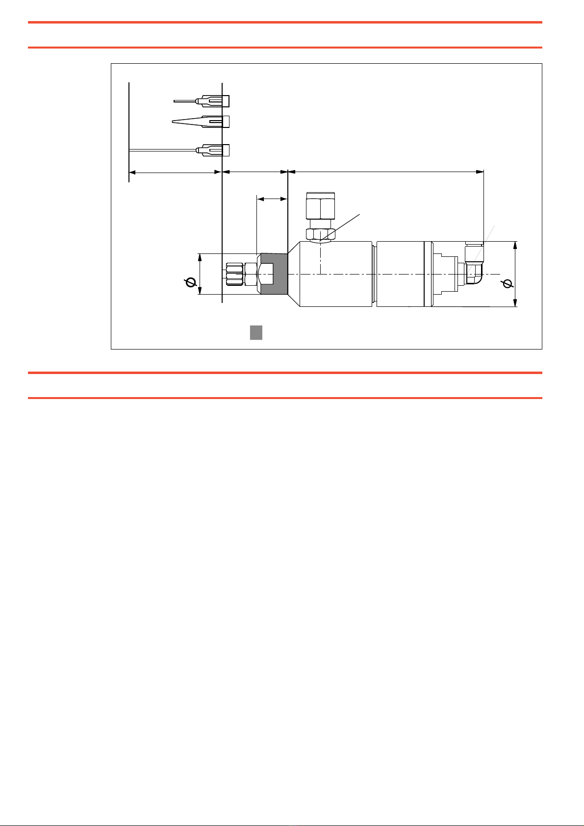
Clamping area
32 95
32
25.5
52
26.5
20
15
R1/8 R1/8

11
4
Installation
4.1
Connecting to the Product Reservoir
97106, 97108, 97127
0.5 ltr.: length 200 mm
2 ltr.: length 275 mm
12
4
Installation
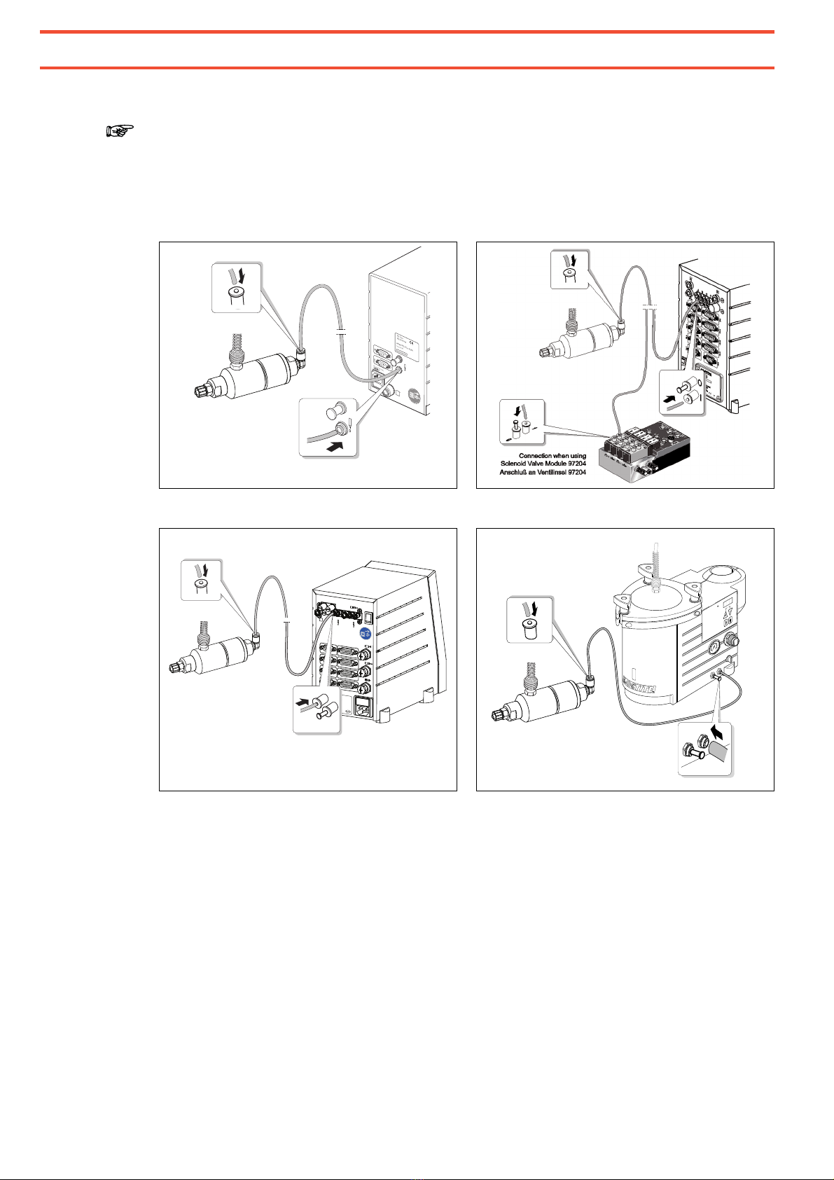
4.2
Connecting to the Controller
Note!
When connecting to the coax-outlet (controller 97102 and 97103/97204) use Coax
Adapter, type no. 8900102! When connecting to the single port, use port Iand
close port O.
97102
971
5
3/97204
97152
97008/
97009
888
CONT
CONT
2
0
30
60 90
120
6
8
10
psi
bar
I
0
XS16
XS18
XS17
XS5 RS 232 XS8 I/O Port
XS3 Flow Monitor
XS2 Reservoir
XS1 Start
XS10 PLC Interface
XS12 Valves
XS11 DC Drive
HenkelAG & Co. KGaA
Standort München
Gutenbergstr.3
D-85748 Garching
100-240 VAC,50/60 Hz
Fuse: 2A T (time-lag)
Power Consumption: 100 W
Made in Germany
Place for Serial No. Sticker
I/0
P in
6-8 bar
0I 0I
AB
P out
0.1-7 bar
O
I
90–260VAC/47–63 Hz
2AM
XS1
XS1: Start
XS2: Reservoir
Henkel AG & Co. KGaA
cat.no.97102
XS2
0
1
1
0
13
5
Dispensing
5.1
Priming the Diaphragm Valve
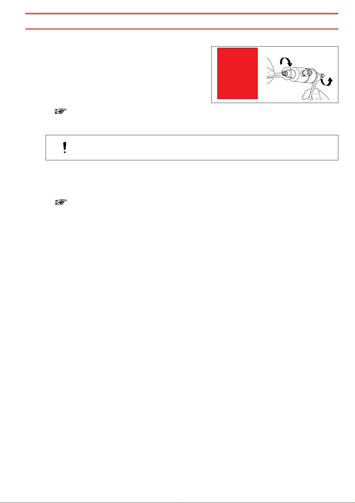
•Before initial operation:
Hand-tighten the valve actuator and
valve body by means of two combination
wrenches (wrench size 17 mm) in
accordance with the data of the sticker
(max.17 Nm). Only then it is guaranteed
that the valve is tight.
Note!
To avoid air bubbles during dispensing, the product feedline and the diaphragm valve
must be filled.
CAUTION!
Place a container under the diaphragm valve since the product will flow out!
•Perform the filling of the product feedline acc. to the operating manual of the used
Controller.
5.2
Adjusting the Dispensed Quantity
Note!
Adjust the dispensing quantity according to Chapter 5 of the operating manual of the
used controller.
5.3
Shutdown
To protect anaerobic products from curing, remove dispensing needle leaving Luer-Lock
adapter
6
exposed to air.
Shutdown for longer Periods.
•Remove product out of the reservoir.
•Purge the diaphragm valve with air until no product run out.
5.4
Returning to Operation
•Insert product bottle into the reservoir.
•Purge the diaphragm valve with air until product run out.
•Check the dispensing quantity acc. to Chapter 5 of the operating manual of the used
controller.
ACHTUNG:
Vor Inbetriebnahme
Ventilober- und
Unterteil (SW 17 mm)
handfest nachziehen
(max 17 Nm).
NOTE:
Hand-tighten valve
top and bottom
(wrench opening
17 mm) prior to first
use (17 Nm max.).

14
5
Dispensing
5.5
Upgrading the Feedline/Fitting
Note!
For viscous products, a feed tube adapter with a 9.5 mm product feedline, type no.
97220, is available by ordering part no. 135561.
•Disconnect the feedline and unscrew the
fitting.
•Screw the new fitting into the shut off
valve 4.

15
6
Care, Cleaning and Maintenance
6.1
Cleaning
The diaphragm valves have to be cleaned if
- idle periods of the dispensing system exceed seven days, and/or
- a different type of product is to be dispensed and/or
-
valves are disassembled for replacement of spare parts.
Liquid residues may be removed with several solvent. Chlorinated hydrocarbons will
obtain optimum results; acetone would be the best alternative among nonCHC solvents.
WARNING!
If chemical products are not properly handled, damage to health can result.
Observe general safety regulations for the handling of chemicals!
If diaphragm valve is cleaned after prolonged idle periods or for a switch to a different
product, be sure to place new Loctite
®
product bottle into the tank, see operating manual
of the used reservoir.
Priming of the feedline, see operating manual of the used controller.
Setting of dispensing parameters, see operating manual of the used controller.
6.2
Maintenance
To ensure trouble-free operation of the diaphragm valves 97135/97136 we recommend
servicing at regular intervals.
•Every 6 months
Replace diaphragm
3
(Repair Kit),
type no. 97271, o
rder code no.
360444
.
Following is a description of diaphragm valve cleaning, disassembly and reassembly
procedures.

16
6
Care, Cleaning and Maintenance
6.2.1
Disassembly
•Disconnect feedline and pneumatic tube
and remove dispensing nozzle.
•Disassemble Diaphragm valve (2 open
end wrenches size 17).
•Carefully remove diaphragm 3from shut
off valve
4
.
Note!
Do not use metal tools! For example use
small wooden spatulas or toothpicks.
When the insert is damaged product can
get in contact with the housing and cures.
•Clean the ring groove.

17
6
Care, Cleaning and Maintenance
6.2.2
Assembly
•Slightly grease threads and neck of
actuator 2.
•Insert new diaphragm 3in shut off
valve 4.
•Screw actuator 2onto shut off valve 4
and tighten securely by hand, then by
using wrench size 17 turn max. 180° to
fix them correctly and get dispensing
valve tight in accordance with the data
of the sticker (max.17 Nm).
•Connect feedline and pneumatic tube and slip on dispensing nozzle.
ACHTUNG:
Vor Inbetriebnahme
Ventilober- und
Unterteil (SW 17 mm)
handfest nachziehen
(max 17 Nm).
NOTE:
Hand-tighten valve
top and bottom
(wrench opening
17 mm) prior to first
use (17 Nm max.).

18
7
Troubleshooting
Type of malfunction Possible causes Correction
No product or too little
product.
– Product feedline and/or pneumatic
hose not connected correctly or
kinked.
•Connect the product feedline correctly.
If kinked, replace it.
– Control pressure not adequate.
Control pressure must be between
5 and 7 bar.
•Check and adjust the control pressure.
– Curing in the product feedline or in
the dispensing needle.
– Curing in the diaphragm valve.
•Replace the product feedline and/or the
dispensing needle.
•Replace the shutoff valve 4and the
diaphragm 3.
– Controller incorrectly adjusted. •Check the controller setting (see
operating manual for the controller).
– Product reservoir not switched on,
depressurized or pressure is too
low.
•Check the reservoir (see operating
manual for the product reservoir).
Diaphragm valve does
not open.
– Actuator 2of the valve is
contaminated with product.
•Replace the actuator 2and the
diaphragm 3.
Dispensing operation is
irregular.
– Actuator 2and shut off valve 4are
tightened too much.
•Back off actuator from shut off valve,
proceeding in small steps,
90° max (1/4 turn).
Dispensing sequence
too short despite long
time setting.
– Disassemble valve and push button
on controller to actuate the actuator:
> air escapes at the plunger.
•Replace the actuator 2and the
diaphragm 3.

19
8
Annex
8.1
Accessories and Spare Parts
Note!
Also see the illustration on page 9.
Pos. No.
Description Type No. Order Code No.
2 Actuator ........................................................................................
97254 338119
3 Repair Kit Diaphragm ....................................................................
97271 360444
4 Shut off Valve Ø 2 mm ..................................................................
97268 333180
4 Shut off Valve Ø 3 mm ..................................................................
97269 360443
– Dispense Needle, Polyethylene – Conical (PPC),
especially for viscous products and large dispensing quantities:
Dispense Needle PPC16GA (50 pcs/box), ID Size 1.19 mm, grey.
Dispense Needle PPC18GA (50 pcs/box), ID Size 0.84 mm,
green.............................................................................................
Dispense Needle PPC20GA (50 pcs/box), ID Size 0.58 mm, pink.
Dispense Needle PPC22GA (50 pcs/box), ID Size 0.41 mm, blue.
97221
97222
97223
97224
88660
88661
88662
88663
– Dispense Needle, Stainless Steel – Standard (SSS),
especially for low viscosity and UV curing products:
Dispense Needle SSS15GA (50 pcs/box), ID Size 1.35 mm,
amber............................................................................................
Dispense Needle SSS18GA (50 pcs/box), ID Size 0.84 mm,
green.............................................................................................
Dispense Needle SSS20GA (50 pcs/box), ID Size 0.58 mm, pink
Dispense Needle SSS25GA (50 pcs/box), ID Size 0.25 mm, red...
97225
97226
97227
97228
88664
88665
88666
88667
– Dispense Needle, Polyethylene – Flexible (PPF),
especially for fast curing products:
Dispense Needle PPF15GA (50 pcs/box), ID Size 1.24 mm,
amber............................................................................................
Dispense Needle PPF18GA (50 pcs/box), ID Size 0.81 mm,
green.............................................................................................
Dispense Needle PPF20GA (50 pcs/box), ID Size 0.48 mm, pink
Dispense Needle PPF25GA (50 pcs/box), ID Size 0.36 mm, red...
97229
97230
97231
97232
142640
142641
142642
142643

20
8
Annex
Pos. No.
Description Type No. Order Code No.
– Dispense Needle, Appryl (PPS),
especially for spot applications, not suitable for UV adhesives:
Dispense Needle PPS20GA (50 pcs./box), ID Size 0.6 mm,
nature ...........................................................................................
97290
397462
– Luer Lock Tip Caps ......................................................................
97248 218275
6 Luer Lock Adapter Kit....................................................................
97233 88672
– Feedline, PTFE, 1/4”.....................................................................
8953672 1257724
– Feedline Upgrade Kit 1/4“ to 3/8” ..................................................
97220 135561
– Repair Kit Sealing Adapter 2.0 (for 97135)....................................
8952235 529530
– Repair Kit Sealing Adapter 3.0 (for 97136)....................................
8952326 529531
– Coupling Product bore Ø 1,5 mm (97135).....................................
8950523 585000
– Coupling Product bore Ø 2,5 mm (97136).....................................
8950560 585001
This manual suits for next models
3
Table of contents
Languages:
Other Henkel Control Unit manuals


Popular Control Unit manuals by other brands


weed instrument
weed instrument EOTec 2000 installation instructions

Contrive
Contrive Quad manual

Meinberg
Meinberg IMS-PIO180 manual

Panasonic
Panasonic PAN9026 Developer's guide

Gemalto
Gemalto Cinterion BGS2-W miniPCIe Hardware interface description

KIESELMANN
KIESELMANN 6268 Translation of the original operating instruction


