Henley Fan 6HE84+LK User manual

6HE84+LK
6HE52+LK
WARNING : Read and follow these instructions carefully and be mindful of all warnings shown throughout.
13.0 KGS.
28.6 LBS.
6HE84+LK
Net weight
11.5 KGS.
25.3 LBS.
6HE52+LK
Net weight
HELICOPTER

P1
WARNING : TO REDUCE THE RISK OF FIRE, ELECTRICAL SHOCK, OR INJURY
TO PERSONS, PLEASE OBSERVE THE FOLLOWING :
READ AND SAVE THESE INSTRUCTIONS
1]. To ensure the success of the installation, be sure to read the instructions and review the diagrams
thoroughly before beginning.
2].
All electrical connections must be made in accordance with local codes, ordinances and/or the
National Electric Code. If you are unfamiliar with the methods of installing electrical wiring and
products, require the services of a qualified and licensed electrician as well as someone who can
check the strength of the supportive ceiling members and make the proper installations and
connections.
3]. Make sure that your installation site will not allow rotating fan blades to come in contact with any
object. Blades should be at least 10 feet from floor when fan is in operation.
4]. If possible, mount ceiling fan on a ceiling joist - the joist must be able to support the motion and weight
of the moving fan. If the fan will be mounted on a ceiling outlet box, a 4" x 2-1/8" deep METAL octagon
box is required ; one UL listed as " suitable for fan support ". The box and its supporting members must
not be able to twist or work loose. DO NOT USE PLASTIC BOXES. Installation on a concrete ceiling should
be performed by qualified personnel.
5]. Blades should be attached after motor housing is hung and in place. Fan motor housing should be
kept in carton until ready to be installed to protect its finish. If you are installing more than one ceiling
fan, make sure that you do not mix fan blade sets.
6]. After making electrical connections, spliced conductors should be turned upward and pushed
carefully up into outlet box. The wires should be spread apart with the grounded conductor and the
equipment - grounding conductor on one side of the outlet box and the " HOT " wires on the other side.
7]. Electrical diagrams are for reference only. Light kits that are not packed with the fan must be UL/ETL listed
and should be installed per the light kit's installation instructions.
8]. After fan is completely installed, check to make sure that all connections are secure to prevent fan
from falling and/or causing damage or injury.
9]. The fan can be made to work immediately after installation. The bearings are adequately charged with grease,
so that under normal conditions, further lubrication should not be necessary.
10]. The fan must be turned off and stopped before reversing fan direction.
11].
12] .
13].
14].
15].
To avoid possible electric shock, be sure electricity is turned off at the main power box before wiring.
The fan is for downrod mount only.
This fan is reversible.
This fan includes optional light kit.
This fan is controlled by remote.
This fan is suitable for indoor use.
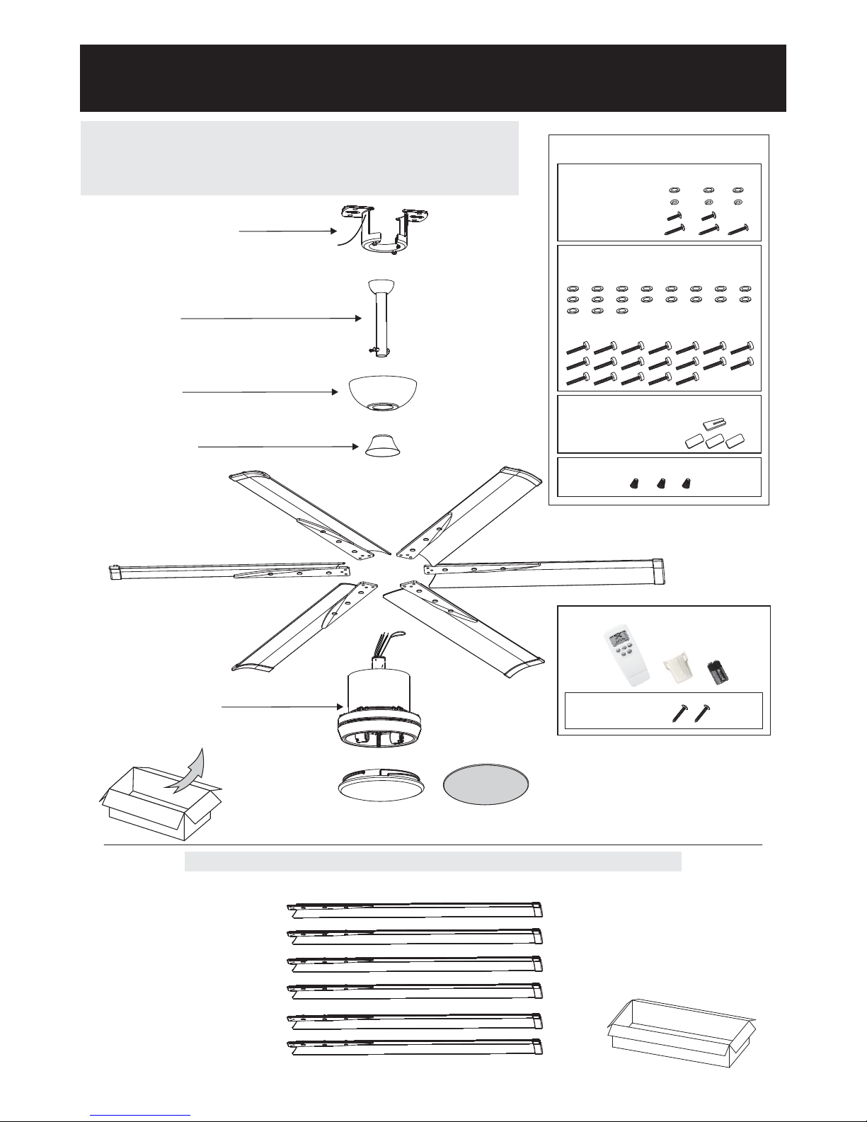
Unpack and inspect fan carefully to be certain
all contents are included.
Mounting Bracket
Canopy
Downrod
P2
Yoke Cover
Glass
Fan Assembly
Bottom plate (For non-light use)
52" Extruded alum. blades(6)
For 6HE52+LK - Unit pack / All in one box
Hardware Bag
For :Blade Balance
Balanced slice x 1
Weight block (3G x 3)
3GM
3GM
3GM
For Blade Installation:
Flat washer spare washerx19(one included)
Blade Screw x 19 (one spare screw included)
Flat Washer x3
Spring Washer x3
Machine Screw x2
Wood Screw x3
For Mounting Plate:
For Wire Connection:
WireNutx3
Note:
This fan is designed for the following 2 sizes of blades:
* 52” alum. blades (6 pcs)- Unit Pack
* 84” alum. blades (6 pcs)- Blades Packed Separutely
extruded
extruded
For 6HE84+LK- Blades packed separately
(84" Extruded alum. blades)
3. CANOPY INSTALLATION 6 pieces per set in a box
Hardware Bag
Wood Screw x2
Remote
*Battery Included
WARNING: blades should be at least 10 feet from floor
OFF OFF OFF
Turn off power at breaker
box to avoid possible
electrical shock.
Use metal outlet box suitable
for fan support.
Outlet box must support 35 lbs min.
Note 1: Note 2:
P3
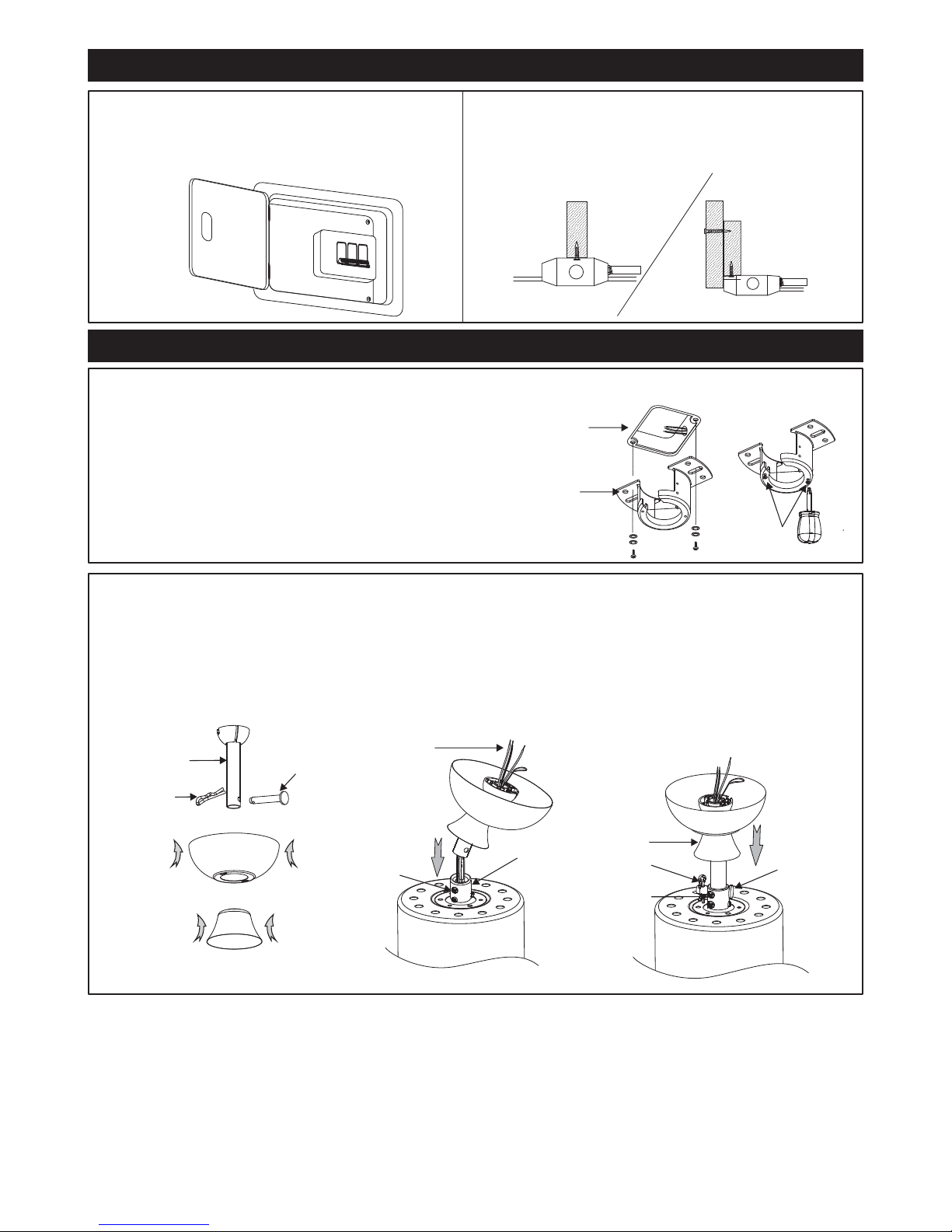
Cross Pin
Cotter Pin
Downrod 1
1
Canopy
Yoke cover
1B. Downrod and YokeInstalling
Remove cross pin and cotter pin from downrod.
Insert downrod through canopy and yoke cover, and feed motor lead wires through downrod.
Loosen 2 downrod jam screws at yoke. Insert downrod assembly into yoke.
Insert the cross pin through yoke & downrod and secure with cotter pin.
Tighten both downrod jam screws to further secure downrod.
Pull down the yoke cover to cover yoke.
1
2
3
4
5
6
Yoke
Yoke cover
Cross Pin
Cotter Pin
Downrod Jam
Screw(2)
(Tightening)
Wires
2
3
5
4
Downrod
Assembly
Downrod Jam
Screw(2)
( ing)
Loosen
6
4
1. HANGING SYSTEM INSTALLATION
1A.Installing mounting bracket to ceiling outlet box
1
2
Install mounting bracket to outlet box in ceiling
by using screws included with the outlet box and
washers from the hardware bag.
Loosen the screws at mounting bracket.
1Outlet Box
2Screw (2)
(Loosening)
Mounting
Bracket

P4
2. WIRE CONNECTION
Follow diagram below and make sure that all exposed wires are secured inside wire nuts or terminal block.
Note : Wires from house may vary in color and may not include ground wire ( green ).
From House
Blue
Brown
From Fan
Blue
Brown
(AC-N)
(AC-L)
(MOTOR-N)
(MOTOR-L)
Green
Green
Green
( from downrod )
( from mounting bracket)
( for ground wire )
*Blue wire from house to blue wire from fan
*Brown wire from house to brown wire from fan
*Ground wire from house to green wires from downrod and from mounting bracket
*Secure with twist - lock wire nuts (provided from hardware bag)
*G
ently push wires into junction box with wire nuts pointing upward.
2B. Making electrical wire connection
2A. Attaching safety cable to ceiling joist
Safety Cable
Safety
cable Flat Washer
Spring Washer
Wood Screw
Outlet Box
Use wood screw, spring washer, and flat
washer from hardware bag. Pass wood
screw through closed loop of safety
cable. Secure wood screw to ceiling joist
through any available slot on mounting
bracket. Make sure safety cable has
been tightened securely.
CAUTION: THE WOOD SCREW AND
ITS SUPPORT MUST BE ABLE TO
FULLY SUPPORT THE WEIGHT OF AT
LEAST 100 LBS.
Canopy
Mounting Bracket
Rotate fan so that the groove on the ball engages
the ridge in the mounting bracket.
Mounting
Bracket
Ridge
Ball Groove
1C. Hanging the fan
Lift fan assembly onto mounting bracket.
Mounting
Bracket
Fan Assembly
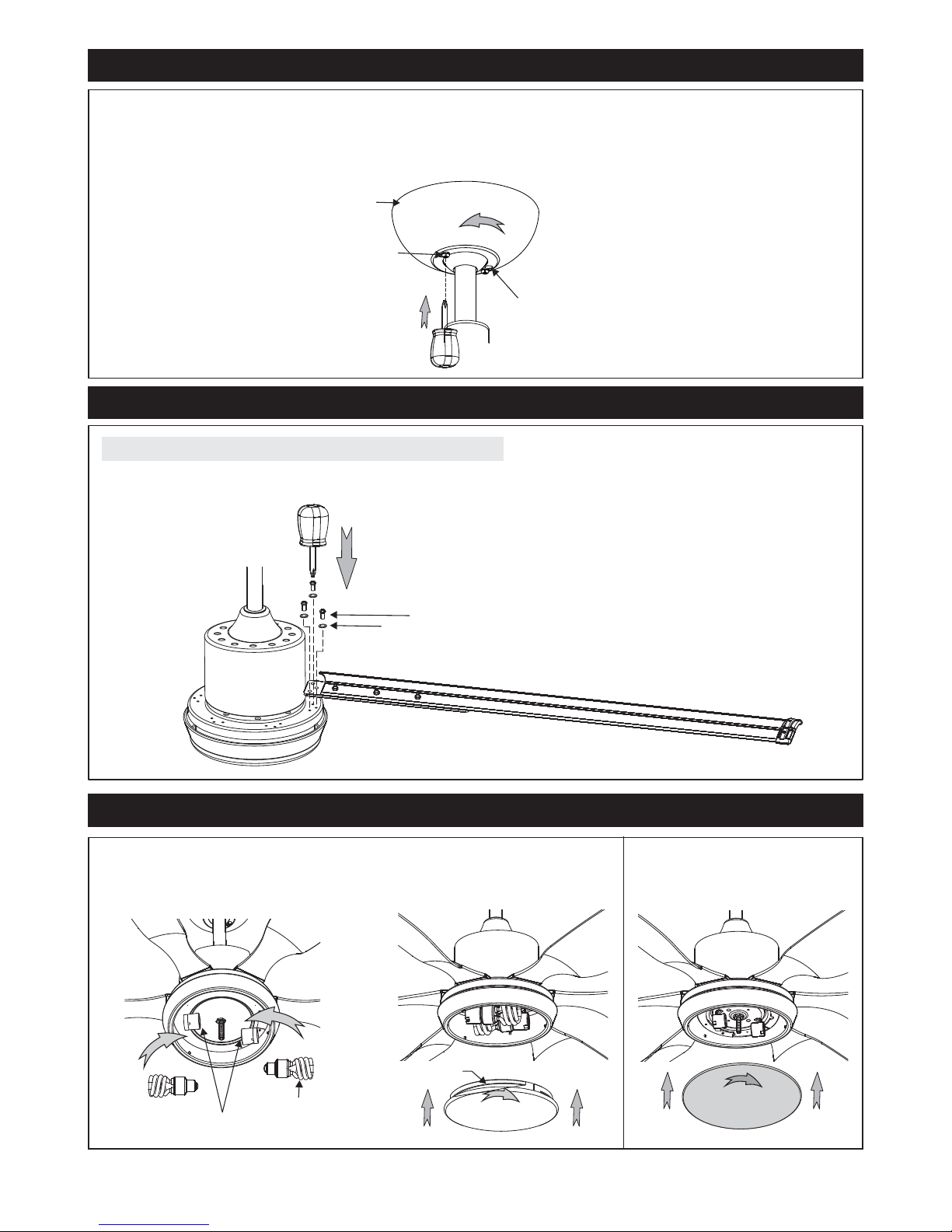
4. BLADE INSTALLATION
5. LIGHT KIT INSTALLATION
5B.
Attach the glass shade by screwing
it onto the light kit pan clockwise.
Install the bulbs
to the medium base sockets properly.
5A.
(NOT included)
Groove
Glass
Shade
Medium Sockets
Bulb(2) Bottom plate
5C.
Attach the bottom plate by screwing
it clockwise onto the light kit pan.
For non-light use:
P5
Attach blades to by using flat washers & screws provided hardware bag.
(* 6 blades are installed firmly.)
fan assembly from
Repeat until all
For 52" / 84" Extruded Alum. Blades
Extruded (6)Alum. Blade
Flat Washer(3)
Blade Screw(3)
3. CANOPY INSTALLATION
1
2
3
Push up canopy until two screws pre-screwed on mounting bracket are engaged with two key holes
on canopy.
Rotate canopy slightly until two pre-installed screw heads are engaged in the narrow end of key holes.
Tighten both screws.
Note: Two screws are pre-installed on mounting bracket for canopy installation.
Key Hole (2)
Canopy
Screw (2)
1
2
3
P6
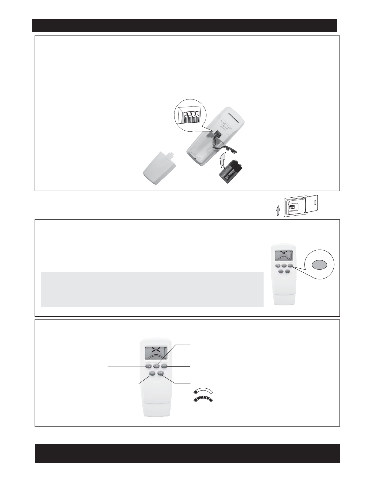
Remove battery cover.
FAN code setting:
There are 4 switches for 16 possible code combinations just in case your house has other fans installed
with the same codes. You may change your code switches by using a small screwdriver or ball point pen
to slide each code switch firmly up or down.
1
2
Note:IFONLYONEFANTOBEINSTALLEDINTHEHOUSE,YOUCANSKIPTHISSTEP.
Install 9V battery x 1 pc.
3
6A. Initial Settings (Back side of Transmitter)
1. Code setting on TRANSMITTER.
6C. SETTING before starting fan.
6.REMOTE SETTING
OFF
OFF
OFF
6B.Turn on power at breaker box for remote setting.
Attention: See "Special note" on next pages if you plan to install MORE THAN
ONE FAN in THE SAME room.
ON
6E. Your fan is ready for operation.
Pressing the button " " for over 5 seconds till the receiver makes Bi-Bi
sound. This fan has completed frequency setting.
OFF
IMPORTANT:
In event of no Bi-Bi sound (fan is failed for setting), do the following step for
re-setting:
Switch off the main power and wait for 10 seconds, then switch on
the power again and do the above setting again.
Note : Do not press any other button on the transmitter before setting as it will
cause the procedure to fail.
1
39V Battery x 1 pc
2
12
3
4
ON
12
3
4
ON
OFF
6D. TRANSMITTER BUTTON
Light switch:
To turn on and off the light.
To turn off the fan
Reversing function
6 speeds
1st Speed: Lowest Speed
6th Speed: Highest Speed
To set the fan in Natural Wind Mode with 2 levels:
"H" : means strong wind.
"L" : means weak wind.

Outlet Box
P7
Special note: to install more than 1 fan in the same room.
If you are installing more than one fan in the same area, the remote setup can affect all fans in the area. To
have precise control over each fan and light, each fan / remote must be set-up by itself. To avoid frequency
interference, please do the following steps so the fans can be operated by its own remote in the same room.
a. First DC fan (#1 fan) has completed its setting and is operating in good condition.
b. Second DC fan (#2 fan) now is completing its assembling steps and ready for “set up”.
The following steps are based on the status of
c. The main switch is “OFF”.
1.Lower the canopy of #1 Fan and disconnect the Black wire.
Put the wire nut on the black wire from the house.
#1 Fan will remember its current setting.
#1 Fan has completed its set up. You are ready to set up the #2 Fan.
Outlet Box
#1 Fan
(Disconnecting)
#2 Fan
Mounting Bracket
Make sure turn off power at breaker box for step 1.
OFF OFF OFF
OFF
Remove battery cover.
FAN code setting:
There are 4 switches for 16 possible code combinations just in case your house has other fans installed
with the same codes. You may change your code switches by using a small screwdriver or ball point pen
to slide each code switch firmly up or down.
1
2
Note:IFONLYONEFANTOBEINSTALLEDINTHEHOUSE,YOUCANSKIPTHISSTEP.
Install 9V battery x 1 pc.
3
1. Code setting on TRANSMITTER.
6A. Initial Settings (Back side of Transmitter)
1
39V Battery x 1 pc
2
ON ECE
1
2
3
4
2. Being sure to set a different Fan Code Setting, perform the Remote Setting steps 6A through 6C
from page 6 on the #2 Fan.
#1 Fan #2 Fan
ON ECE
1
2
3
4
ON ECE
1
2
3
4

3. Turn off the power from main switch and install the AC Black wires to the #1 Fans that you removed from
and secure with wire nut.step 1
OFF OFF OFF
OFF
#2 Fan has completed its setting.
Outlet Box
Mounting Bracket
#1 Fan
Outlet Box
#2 Fan
4. Turn on the power from main switch and now each of these two fans are operated by its own remote
individually.
OFF
OFF
OFF
ON
NOTE: For more than two fans, the same rules apply. Make sure only one fan at a time is connected to
power when doing the Remote Setting. Already completed fans should be disconnected until all fans have
completed the Remote Setting process.
(operating now)
(operating now)
#1 Fan
Outlet Box
Outlet Box
#2 Fan
P8
OFF
OFF
OFF
6B.Turn on power at breaker box for remote setting. ON
6C. SETTING before starting fan.
Pressing the button " " for over 5 seconds till the receiver makes Bi-Bi
sound. This fan has completed frequency setting.
OFF
IMPORTANT:
In event of no Bi-Bi sound (fan is failed for setting), do the following step for
re-setting:
Switch off the main power and wait for 10 seconds, then switch on
the power again and do the above setting again.
Note : Do not press any other button on the transmitter before setting as it will
cause the procedure to fail.
OFF
This manual suits for next models
1
Table of contents


