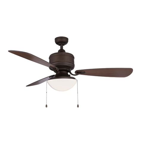
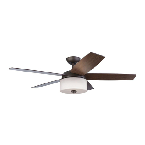
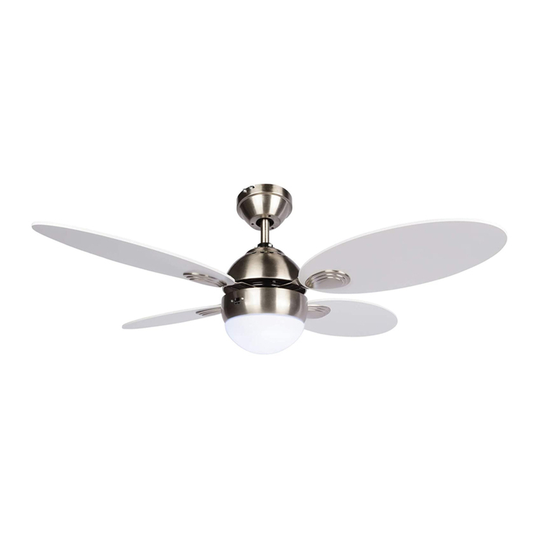
NOMA Quatra 052-9329-2 User manual

model no. 052-9329-2
Total weight of fan plus light kit are 7.4 kgs
Instruction Manual
IMPORTANT: Please read and understand this manual before any assembly. Before
beginning assembly of product, make sure all parts are present. Compare parts
with exploded view. If any part is missing, or if you have any questions, contact
customer service at 1-866-827-4985 (toll free).
Quatra 52" Ceiling Fan
Toll Free: 1-866-827-4985

Table of Contents
IMPORTANT: RETAIN FOR FUTURE REFERENCE, AND READ CAREFULLY
Toll Free : 1-866-827-4985 model no. 052-9329-2
Tools required for assembly
............................................................................................................5
Assembly .....................................................................................................................................................5
Operation ....................................................................................................................................................9
Maintenance ..............................................................................................................................................10
Care and cleaning ..........................................................................................................................................10
Troubleshooting .................................................................................................................................... 10
Environmental protection .............................................................................................. 11
Warranty .....................................................................................................................................................12
.................................................................................................................................... 3
Exploded view
.......................................................................................................
............................. 2
Table of Contents
...............................................................................................................4
Rules for safe installation
.................................................................................................. 4
Important safety instructions

3
Exploded View
3
No Description Qty
A
B
C
D
E
Mounting bracket
Downrod
Canopy with cap
Flange cover
Motor
1
1
1
1
1
No Description Qty
FLight Kit 1
GBlades 4
H
H
A
B
C
D
E
F
I
Remote control 1
Receiver 1
EXPLODED VIEW
G

3
Instructions
IMPORTANT SAFETY INSTRUCTIONS
Please read and save these instructions.
Note:
Always turn the power o
·
A dry dust cloth is suitable for most cleanings.
· Should the ceiling fan become wet, have a qualified electrician inspect it before next use.
·
In order to comply with safety regulations and to avoid safety hazards, ceiling fan repairs must be
·
carried out by qualified personnel.
·
Pay attention to the ceiling fan blades when acleaning, painting or working nearby.
·
Children do not recognize the dangers that may occur when operating a ceiling fan. Keep children
away
from ceiling fans.
DO NOT:
· Expose the ceiling fan to water or immerse it in water.
· Operate the ceiling fan if it shows any signs of damage or if it has been dropped.
·
Attempt to remove any parts of the housing or insert any object while the ceiling fan is
operating.
· Position the ceiling fan on or near hot surfaces such as stove tops, or near open flames.
· Expose the ceiling fan to rain or moisture.
. Operate the ceiling fan outdoors or
with wet hands.
· Use the reverse switch while the fan blades are in motion.This could result in
damage to the ceiling fan.
RULES FOR SAFE INSTALLATION
This ceiling fan is designed for household use only and not for commercial applications. No responsibility
is accepted for damage resulting from improper use or noncompliance with the instructions.
CAUTION!
·
To avoid possible electric shock, be sure electricity at the fuse box or the circuit breaker
is turned o
·
All wiring must be done in accordance with national and local wiring codes. Consult a
qualified
electrician to ensure correct branch circuit conductor.
· Follow the recommended instructions for the proper method of wiring for the new ceiling
fan.The ceiling fan must be grounded as a precaution against possible electric shock.
· If you do not have sufficient electrical wiring knowledge, have the fan installed by a licensed
electrician.
· Mount the lowest moving parts at least 6’ 11” (2.1 m) above floor or ground level.
· Make sure the ceiling fan is securely fastened to the ceiling.
· All screws must be checked and re-tightened where necessary before fan operation.
WARNING!
·
To prevent injur
y
, make sure the fan blades are not bent and that there are no objects
within the rotation area.
·
The important precautions, safeguards and instructions appearing in this manual are not
meant to cover all possible situations. It must be understood that common sense and
caution are factors which cannot be built into the product.
Not suitable for use with solid-state speed controls.
Toll Free: 1-866-827-4985 model no. 052-9329-2
4
·

5
Assembly
TOOLS REQUIRED FOR ASSEMBLY
After opening the package you should find all the necessary parts for installing this ceiling fan.
The box should also include:
12
3
ASSEMBLY
Preparing for installation
Getting ready
. Unpack and inspect carefully to make sure all parts are
included and not damaged (see Fig. 1). Lay all pieces out
on a working space.
possible electric shock (see Fig. 2).
Choosing a location for the ceiling fan
32" (81.3 cm) from adjacent walls or obstructions.
. Choose a loc
. To reduce the risk of fire, electric shock, or personal injury, mount to outlet box marked "Acceptable
for Fan Support" and use mounting screws provided with the outlet box. Most outlet boxes
commonly used to support light fixtures are not acceptable for fan support and may need to be
replaced. Consult a qualified electrician if in doubt.
ation where there is a high enough ceiling clearance (at least 2.1 m (6' 11") from the floor
to the ceiling fan’s lowest moving part).
Mounting options
Drop-mount (for normal ceilings)
. This method is preferred if the ceiling is sloped or vaulted, or if the ceiling
is extra high, requiring the need of a downrod (see Fig. 3).
re
Parts Pack containing:
2 wood screws with flat washers
2 5/32” screws with lock washers
3 wire connectors
1 “J” hook
1 zip tie
3 balance pieces
1 balance clip
1 instruction sheet
1 Downrod clip
1 Downrod pin

2. Drop-mount
6
1. Mounting bracket
Installation:
The installation is to be in accordance with the National Electrical Code, ANSI/NFPA 70 and local codes.
Assembly
ASSEMBLY
. Locate 12 blade attachment screws in hardware pack. Slide
blade through motor and align holes. Insert 3 blade attachment
screws with finger. Tighten securely with a screwdriver
(not supplied). Repeat for the remaining blades. (Figure 4-1)
. Install the light kit up to the motor housing and turn clockwise
until tight (Figure 4-2)
3. Attach blade to motor
.
.
.
Remove the canopy from the mounting bracket by removing Figure 1
Figure 2
Figure 3
Mounting
bracket screw
Mounting
bracket
Slot
Downrod
Downrod
Canopy
Pin
Yoke set
screws
Flange
Tab
the two mounting bracket screws and star washers from the
round holes in the canopy. Then loosen the other two mounting
bracket screws from the L-shaped slots. Retain the mounting
bracket screws and star washers for later. (Figure 1)
With wiring extending out of downrod, cut the excess wire
with wire cutter (not included). Then strip
mounting bracket. Rotate the downrod until the tab in the
mounting bracket is seated in the slot in the downrod ball.
(Figure 2)
downrod into the
For best fan performance and safety, make sure the mounting
plate is fitted to a level ceiling joist or ceiling support. If the
mounting position is not level, hard packing material should be
used to make the plate level.
. Slide downrod through canopy and flange cover.
. Thread electrical wires through downrod and pull extra wire
slack from the upper end of the downrod.
. Loosen yoke set screw and nut and remove pin if preinstalled.
Place downrod into the motor housing and insert pin.
Tighten yoke set screw and nut securely. (Figure 3)
Figure 4-1
Blade
Blade
Figure 4-2
Toll Free: 1-866-827-4985 model no. 052-9329-2

ASSEMBLY
Assembly
7
4.
WARNING
before wiring.
!
!
!
Once the connection has been made, the receiver inserts into the drop rod hanging bracket.
The canopy comes up to cover the receiver and bracket .
Installing Receiver Assembly
!
Remote and Receiver Pairing
Codes are set by pushing the location of the dip switches located on the transmitter and receiver
up or down. It is important that the code used for both the remote and receiver are identical for
the two devices to be able to communicate; otherwise the remote will not be able to control
the fan.
If you plan to install more than one fan then each fan will require the remote and receiver to
use a unique code, or else one remote will be able to control more than one fan.
4. Wiring instructions
YRETTAB
ensure
OPEN BATTERY HOUSING
COVER BY PRESSING DOWN
AND SLIDING OUT

8
Assembly
Toll Free: 1-866-827-4985 model no. 052-9329-2
Downrod
Receiver
Antenna:
DO NOTCUT
OR SPLICE
aluminum ball
b
c
a
e
)
WARNING:Be sure no bare wire or wir
The splices after being made should be turned upward and pushed carefully up into
the outlet box.
e strands are visible after making connections. Plac
green and white connections on opposite side of box from the black and blue (if applicable
connections.
After making the wire connections, the wires should be spread apart with the grounded
conductor and the equipment-grounding conductor on one side of the outlet box and the
ungrounded conductor on the other side of the outlet box.

a
b
Operation
9
. Restore power to ceiling fan and test for proper operation.
. The fan remote control controls the fan settings:
Forward function
. On this setting, the fan will turn counter-clockwise
warmer weather to circulate hot air away from
your living space (see Fig. a).
Reverse function
. On this setting, the fan will turn clockwise. Use this
function during cooler weather to re-circulate warm
air (see Fig. b).
HI : Turn on the fan at high speed.
MED : Turn on the fan at medium speed.
LOW : Turn on the fan at low speed.
LIGHT: ON/OFF : Press and release immediately to turn
DIMMER : Press and hold to dim or brighten
lights to the desired level and release
(Only for the tungsten bulb).
OPERATION
LIGHT
ON/OFF
HI
MED
DIMMER
FAN OFF
LOW
Forward and reverse direction function.
This ceiling fan is equipped with a reverse switch
for downward or upward air-flow.
Note: Do not touch the reverse switch when the fan blades are in motion.
Reverse switch
Forward Reverse
switch housing
Remove the battery cover from the back of the remote control
and insert 2 AA (fig.a) /9V batteries (fig.b)(included). Replace
the battery cover.
ab
9V
Battery
2AA
2AA

Troubleshooting
10
MAINTENANCE
. Because of the fan’s natural movement, some connections may become loose. Check the support
connections, brackets and blade attachments twice a year. Make sure they are secure.
. There is no need to oil your fan.The motor has permanently lubricated bearings.
CARE AND CLEANING
. Dust your fan periodically with a soft, dry cloth. Do not use harsh cleaners or materials as they may
damage the unit.
. To prevent bending the blades during cleaning, support the blades so that no pressure is applied to
them.
Caution!
Do not allow water to come in contact with fan blades or the ceiling fan. Doing so will create
fire and/or shock hazards, damaging property.
TROUBLESHOOTING
If problems persist, seek help from a certified electrician.
Problem
Fan is noisy
during
operation
Fan does not
start
Possible reason
. Blade screws are loose.
. The mounting bracket or canopy is loose.
. Screws securing decorative housing to
hanger are loose.
. Light kit or bulb are loose.
. Screws securing downrod to hanger are
loose.
. Wire connectors are vibrating against the
inside of canopy.
. Light kit or light bulb is not firmly
attached.
. Canopy is rattling against ceiling.
. Motor housing screws have come loose.
. Fuse is blown, or circuit breaker has
tripped.
. Loose or incorrect power line
connections to the fan or switch wires.
Solution
. Tighten screws on blades with a
screwdriver.
. Check and tighten the screws.
. Tighten by hand, as necessary.
. Check and tighten screws.
. Disconnect power at fuse box, loosen
canopy and re-position connectors.
. Remove and re-attach.
. Be sure canopy is not touching ceiling.
. Check and tighten the screws.
. Check main fuse and branch circuit
fuses or circuit breaker. Repair as
necessary.
. Check all the wire connections to
fan and housing wiring. Repair as
necessary.
Caution! Make sure the main
Toll Free: 1-866-827-4985 model no. 052-9329-2

3. Drop-mount and hands-free wiring
Troubleshooting
11
13
TROUBLESHOOTING
Problem
Light does
not work
Fan does
not seem to
move much
air
Fan wobbles
or shakes
excessively
Possible reason
. Wires are not properly connected.
. Fan is in reverse (blades are moving in
clockwise direction).
. Fan is not properly located.
. Screws securing fan blade clips to motor
are loose.
. Fan blade and its blade clip are not
fastened securely.
. Canopy and mounting bracket are not
tightened securely.
Touching
ceiling
Solution
. Ensure wire connector in switch
housing is connected.
. Counter-clockwise (forward) is
recommended in warm weather.
rotation to stop. Use the eraser end
of a pencil to change the forward/
reverse slide switch.
. Place fan in the centre of the room
so there is at least 12" (30 cm)
between the end of the blades and
walls or other obstructions.
. Make sure that screws which attach
fan blade clips to motor are fastened
and tightened.
. Tighten screws of fan blade to blade
clip securely.
. Ensure that canopy and mounting
bracket are tightened securely to
ceiling joist.
ENVIRONMENTAL PROTECTION
Used electrical appliances are recyclable and should not be discarded in your regular
domestic waste! Please actively support us in conserving resources and protecting the
environment by returning this appliance to a collection centre (if available).
Battery must be recycled or disposed of properly. Dispose of as per the requirements
of your local municipality.
Attention: Operation is subject to the following two conditions: (1) This device may not
cause interference. (2) This device must accept any interference, including interference
that may cause undesired operation of the device.
!

Warranty
12
WARRANTY
This Noma fan carries a llimited one (1) year warranty against defects in workmanship and materials.
Noma agrees to replace the defective product free of charge within the stated warranty period, when
returned by the original purchaser with proof of purchase. This product is not guaranteed against wear
or breakage due to misuse and/or abuse.
Made in China
Imported by Noma Canada,Toronto,Canada M4S 2B8
Subject to the conditions and limitations described below, this product, if returned to us with proof of
purchase within the stated warranty period and if covered under this warranty, will be repaired or
replaced (with the same model, or one of equal value or specification), at our option. We will bear the
cost of any repair or replacement and any costs of labor relating thereto.
These warranties are subject to the following conditions and limitations:
a) a bill of sale verifying the purchase and purchase date must be provided;
b) this warranty will not apply to any product or part thereof which is worn or broken or which has
become inoperative due to abuse, misuse, accidental damage, neglect or lack of proper installation,
operation or maintenance (as outlined in the applicable owner’s manual or operating instructions)
or which is being used for industrial, professional, commercial or rental purposes;
c) this warranty will not apply to normal wear and tear or to expendable parts or accessories that
may be supplied with the product that are expected to become inoperative or unusable after a
seasonable period of use;
d) this warranty will not apply to routine maintenance and consumable items such as, but not limited
to, blades, tune-ups or adjustments;
e) this warranty will not apply where damage is caused by repairs made or attempted by others
(i.e. persons not authorized by the manufacturer);
f) this warranty will not apply to any product that was sold to the original purchaser as a
reconditioned or refurbished product (unless otherwise specified in writing);
g) this warranty will not apply to any product or part thereof if any part from another manufacturer
is installed therein or any repairs or alterations have been made or attempted by unauthorized
persons;
h) this warranty will not apply to normal deterioration of the exterior finish, such as, but not limited
to, scratches, dents, paint chips, or to any corrosion or discolouring by heat, abrasive and chemical
cleaners; and
i) this warranty will not apply to component parts sold by and identified as the product of another
company, which shall be covered under the product manufacturer’s warranty, if any.
Additional Limitations
This warranty applies only to the original purchaser and may not be transferred. Neither the retailer nor
the manufacturer shall be liable for any other expense, loss or damage, including, without limitation,
any indirect, incidental, consequential or exemplary damages arising in connection with the sale, use or
inability to use this product.
Notice to Consumer
This warranty gives you specific legal rights, and you may have other rights, which may vary from
province to province. The provisions contained in this warranty are not intended to limit, modify, take
away from, disclaim or exclude any statutory warranties set forth in any applicable provincial or
federal legislation.
Toll Free: 1-866-827-4985 model no. 052-9329-2

N° de modèle: 052-9329-2
Poids total du ventilateur et de l'ensemble éclairage est de 7,4 kg
Mode d’emploi
IMPORTANT: Veuillez lire ce guide et bien le comprendre avant de
commencer l’assemblage. Assurez-vous que toutes les pièces sont
présentes avant de commencer l’assemblage. Comparez les pièces
avec la vue éclatée. S’il manque une pièce ou si vous avez des
questions, communiquez avec le service à la clientèle au numéro
sans frais: 1866827-4985.
Ventilateur de plafond de 52po Quatra
Sans frais: 1866827-4985

Table des matières
IMPORTANT: CONSERVEZ CE GUIDE À TITRE DE RÉFÉRENCE ET LISEZ-LE ATTENTIVEMENT
Sans frais: 1866827-4985; modèle no052-9329-2
.....................................................................................................5
...............................................................................................................................................5
....................................................................................................................................................9
..............................................................................................................................
................10
..............................................................................................................................10
..............................................................................................................................
...........................................................................................
...... 10
11
.....................................................................................................................................................12
.......................................................................................................
............................. 3
.......................................................................................................
............................. 2
Table des matières
Vue éclatée
Consignes de sécurité importantes
Règles relatives à l’installation sécuritaire
Outils requis pour l’assemblage
Assemblage
Utilisation
Entretien
Entretien et nettoyage
Dépannage
Protection de l’environnement
Garantie
............................................................................4
........................................................................................ 4

3
VUE ÉCLATÉE
3
Non Description Qté Non Description Qté
A
B
C
D
E
Support de fixation
Tige
Toit
Couvercle de bride
Moteur
1
1
1
1
1
F
Ensemble d’éclairage
1
GLames 4
H
H
A
B
C
D
E
F
I
Télécommande 1
Récepteur 1
VUE ÉCLATÉE
G

3
Directives
CONSIGNES DE SÉCURITÉ IMPORTANTES
Lisez et conservez les présentes instructions!
Remarque:
Toujours éteindre l’appareil avant de faire l’entretien du ventilateur de plafond.
·
Un chion sec est le mieux adapté pour la plupart des nettoyages.
· Si le ventilateur de plafond devient mouillé, demandez à un électricien compétent de l’inspecter avant la
prochaine utilisation. Afin de respecter les règlements de sécurité et pour éviter les risques d’accident, les
réparations du ventilateur de plafond doivent être eectuées par du personnel qualifié.
·
·
·
Attardez-vous aux pales du ventilateur de plafond lorsque vous nettoyez, peinturez ou faites des
travaux à proximité.
·
Les enfants ne reconnaissent pas les dangers potentiels lors de l’utilisation d’un ventilateur de plafond.
Tenez les enfants à l’écart des ventilateurs de plafond.
À NE
PAS
FAIRE:
· Exposer le ventilateur de plafond à l’eau ou l’immerger dans l’eau.
· Utiliser le ventilateur de plafond s’il montre des signes de dommages ou s’il a été échappé.
·
Tenter de retirer des pièces du boîtier ou d’insérer un objet pendant que le ventilateur de
plafond fonctionne.
· Positionner le ventilateur de plafond sur ou près de surfaces chaudes, comme les cuisinières,
ou près de flammes nues.
· Exposer le ventilateur de plafond à la pluie ou l’humidité.
. Faire fonctionner le ventilateur de plafond à l’extérieur ou avec les mains mouillées.
· Utiliser le commutateur de marche arrière pendant que les pales du ventilateur sont en
mouvement. Cela pourrait causer des dommages au ventilateur de plafond.
AVERTISSEMENT!
·
Afin de prévenir les blessures, assurez-vous que les pales du ventilateur ne sont pas pliées
et qu’il n’y a pas d’objets dans l’aire de rotation.
·
Les précautions, mesures de protection et instructions importantes figurant dans ce manuel
ne sont pas conçues pour couvrir toutes les situations possibles. Il doit être entendu que le
gros bon sens et la précaution sont des facteurs qui ne peuvent pas être intégrés au produit.
RÈGLES RELATIVES À L’INSTALLATION SÉCURITAIRE
Ce ventilateur de plafond est conçu pour un usage domestique et non commercial. Aucune responsabilité
n’est acceptée pour les dommages causés par l’utilisation inadéquate ou le non-respect des instructions.
ATTENTION!
·
Afin d’éviter les décharges électriques, assurez-vous que le courant dans le coret de
fusibles ou le disjoncteur est éteint avant d’eectuer le câblage.
·
Tout le câblage doit être eectué en conformité avec les codes de câblage nationaux
et locaux. Consultez un électricien qualifié pour vous assurer de l’exactitude du conducteur
de circuit de dérivation.
· Suivez les instructions recommandées pour la bonne méthode de câblage pour le nouveau
ventilateur de plafond. Le ventilateur de plafond doit être mis à la terre par mesure de
précaution contre la possibilité de décharges électriques.
·
· Si vous n’avez pas susamment de connaissances au sujet du câblage électrique, faites
installer le ventilateur par un électricien qualifié.
· Fixez les pièces mobiles les plus basses à au moins 2,1m (6pi 11po) au-dessus du sol.
· Assurez-vous que le ventilateur de plafond est bien fixé au plafond.
Toutes les vis doivent être vérifiées et resserrées au besoin avant d’utiliser le ventilateur.
Ne convient pas pour l’utilisation avec des commandes de vitesse à semi-conducteurs.
4
·
Sans frais: 1866827-4985; modèle no052-9329-2

5
ASSEMBLAGE
OUTILS REQUIS POUR L’ASSEMBLAGE
Après l’ouverture de l’emballage, vous devriez trouver toutes les pièces nécessaires pour l’installation de
ce ventilateur de plafond. La boîte doit aussi comprendre:
12
3
ASSEMBLAGE
Préparation en vue de l’installation
Se préparer
. Déballez et inspectez soigneusement l’appareil afin
de vous assurer que toutes les pièces sont incluses
et ne sont pas endommagées (voir la figure1).
Déposez toutes les pièces dans un espace de travail.
Éteignez le courant au coret de fusibles ou au
disjoncteur de protection pour éviter les décharges
électriques (voir la figure2).
Choisir un emplacement pour le ventilateur de plafond
. Choisissez un emplacement où il y a un plafond haut (au moins 2,1m ou 6pi11po entre le sol et
la pièce mobile la plus basse du ventilateur).
. Pour une circulation de l’air ecace, un ventilateur doit être situé au centre de la pièce, ou à au
moins 81,3cm (32po) des murs adjacents ou des obstacles.
. Pour réduire les risques d’incendie, de décharge électrique ou de blessures, fixer à une boîte à
prises qui peut supporter un ventilateur et utiliser les vis de montage fournies avec la boîte à
prises. La plupart des boîtes à prises généralement utilisées pour fixer des luminaires ne sont
pas appropriées pour soutenir un ventilateur; vous pourriez donc devoir la remplacer.
Consultez un électricien qualifié au besoin.
Options de montage
Montage surbaissé (pour plafond normal)
. Cette méthode est privilégiée pour les plafonds en pente, en voûte ou
très élevés qui exigent l’utilisation d’une tige (voir figure3).
Paquet de pièces comprenant:
2 Vis à bois avec rondelles plates
Connecteurs de fils
2 Vis de 5/32po avec rondelles
de blocage
3
1 Crochet en J
1 Attache autobloquante
3 Pièces d’équilibrage
1 Pince d’équilibrage
1 Feuille de directives
1 Goupille de tige
1 Broche de tige

2. Surbaissé
Sans frais: 1866827-4985; modèle no052-9329-2
6
1. Support de fixation
Installation:
L’installation doit être conforme au Code national de l’électricité, ANSI/NFPA70 et avec les codes locaux.
ASSEMBLAGE
ASSEMBLAGE
. Trouvez 12vis de fixation de pales dans le paquet de quincaillerie.
Glissez la pale à travers le moteur et alignez les trous. Insérez les
3vis de fixation de pales avec les doigts. Serrez solidement avec
un tournevis (non compris). Répétez l’opération pour les pales
restantes. (Figure4-1)
. Installez l’ensemble d’éclairage jusqu’au boîtier du moteur et
serrez en tournant dans le sens horaire (figure4-2).
3. Fixez les pales au moteur.
.
.
Retirez le boîtier du support de montage en retirant les deux vis
et les rondelles en étoile du support de montage des trous ronds
dans le boîtier. Puis, desserrez les deux autres vis du support de
montage dans les fentes en forme de «L». Conservez les vis et
de rondelles en étoile du support de montage pour plus tard.
(Figure1)
Prenez le câblage qui sort de la tige et coupez le surplus de
câblage avec un coupe-fil (non compris). Enlevez ensuite 1/2
po d’isolant au bout de chaque fil. Levez la tige dans le support
de montage. Tournez la tige jusqu’à ce que l’onglet du support
de montage repose dans la fente du globe de la tige. (Figure2)
Image1
Image2
Figure3
Vis du support
de montage
Support de
fixation
Fente
Tige
Tige
Toit
Broche
Vis de pression
de l’étrier
Bride
Onglet
Pour obtenir un rendement sécuritaire optimal, assurez-vous
que la plaque de support du ventilateur soit fixée à une solive
de plafond ou un support de plafond à niveau. Si la position
de montage n’est pas à niveau, des matériaux d’emballage
rigides doivent être utilisés pour mettre la plaque à niveau.
. Faites glisser la tige à travers le boîtier et le couvercle de bride.
. Passez soigneusement le câblage électrique dans la tige et tirez
le surplus de câblage à partir du haut de la tige.
. Desserrez la vis de pression et l’écrou de l’étrier, puis retirez la
goupille et la pince si déjà installées. Placez la tige dans le boîtier
du moteur et insérez la goupille. Serrez fermement la vis de
pression et l’écrou de l’étrier. (figure3)
Figure4-1
Pale
Pale
Figure 4-2

ASSEMBLAGE
ASSEMBLAGE
7
4.
AVERTISSEMENT: Pour éviter les décharges électriques, assurez-vous que le courant est éteint
au coret de fusibles principal avant d’eectuer le câblage.
!
!
!
Une fois la connexion eectuée, le récepteur s’insère dans le support de suspension de la tige.
Le boîtier vient couvrir le récepteur et le support.
Installation du récepteur
!
Jumelage de la télécommande et du récepteur
Les codes peuvent être configurés en appuyant en haut ou en bas des commutateurs DIP situé
sur l’émetteur et le récepteur. Il est important que le code utilisé pour la télécommande et le
récepteur soit identique afin que les deux appareils puissent communiquer, sinon la
télécommande ne pourra pas contrôler le ventilateur.
Si vous avez l’intention d’installer plus d’un ventilateur et que vous ne souhaitez pas qu’une
télécommande puisse contrôler plus d’un ventilateur, chaque combinaison de télécommande
et de récepteur devra avoir son propre code.
4. Directives de câblage
YRETTAB
OUVREZ LE COUVERCLE DU
COMPARTIMENT À PILES EN
APPUYANT VERS LE BAS ET
EN LE GLISSANT HORS DU
COMPARTIMENT.
COMMUTATEUR DIP
RÉCEPTEUR
ÉMETTEUR
ANTENNE
PILE(S)
Laissez déconnecté et ne pas couper.
APRÈS L’INSTALLATION

Entre le ventilateur et le récepteur:
Entre le récepteur et les câbles principaux:
Branchez le fil noir portant la mention «L» du ventilateur au fil noir portant la mention
«AU MOTEUR L» sur le récepteur.
Branchez le fil bleu portant la mention «LUMIÈRE» à partir du ventilateur au fil bleu
portant la mention «LUMIÈRE» sur le récepteur.
Branchez le fil blanc portant la mention «N» du ventilateur au fil blanc portant la mention
«AU MOTEUR N» sur le récepteur.
Branchez le fil sous tension noir portant la mention «CA ENTR. L» du récepteur au fil sous
tension (généralement noir) de la boîte à prises.
Branchez le fil neutre blanc portant la mention «CA ENTR. N» du récepteur au fil neutre
(généralement blanc) de la boîte à prises.
Branchez les câbles de mise à la terre verts du support de montage et du dôme au câble
de mise à la terre (nu ou vert) de la boîte à prises.
Boîte à prises
(câbles principaux)
8
ASSEMBLAGE
Tige
Récepteur
CA ENTR. L AU MOTEUR N
AU MOTEUR L
LUMIÈRE LUMIÈRE
Fil de terre
Fil de mise à la terre vert du
support de montage et du
globe en aluminium
CA ENTR. N
Antenne:
NE PAS COUPER
OU ÉPISSER
b
c
a
AVERTISSEMENT: Assurez-vous qu’aucun fil nu ou toron métallique n’est visible après avoir
réalisé la connexion. Placez les connecteurs verts et blancs sur le côté opposé des connecteurs
noirs et bleus de la boîte (s’il y a lieu).
Lorsque les fils sont associés, reliez-les en tordant les extrémités elochées ensemble (voir figurea).
Vissez les connecteurs de fils (3sont fournis) sur le dessus des fils torsadés (voir la figureb).
Fixez-les en place avec du ruban isolant (voir la figureC).
Lorsque toutes les épissures sont eectuées, elles doivent être tournées vers le haut et poussées
soigneusement dans la boîte à prises.
Après avoir réalisé les connexions, les fils doivent être séparés– le conducteur de mise à
la terre et le conducteur de mise à la terre pour l’équipement sur un côté de la boîte à
prises et le conducteur non mis à la terre de l’autre côté de la boîte à prises.
Sans frais: 1866827-4985; modèle no052-9329-2
Table of contents
Languages:
Other NOMA Fan manuals

NOMA
NOMA Schoolhouse 42" User manual

NOMA
NOMA 052-9335-6 User manual

NOMA
NOMA ASHTON User manual

NOMA
NOMA 043-7018-6 User manual

NOMA
NOMA Austin User manual

NOMA
NOMA 043-6164-2 User manual

NOMA
NOMA 052-4744-2 User manual

NOMA
NOMA 043-5991-8 User manual

NOMA
NOMA Miles User manual

NOMA
NOMA Estate052-6964-6 User manual

NOMA
NOMA Loen User manual

NOMA
NOMA Arctic User manual

NOMA
NOMA 052-9340-2 User manual

NOMA
NOMA Lakeside 52" User manual

NOMA
NOMA Mercer 54" User manual

NOMA
NOMA 052-8398-2 User manual

NOMA
NOMA 052-6972-6 User manual

NOMA
NOMA 052-4345-2 User manual

NOMA
NOMA 043-5221-2 User manual

NOMA
NOMA 043-7020-8 User manual