Henry Pratt Company AirPro Max WAR Series User manual
Operation and
Maintenance Manual
Document #: APMAVOM Revision Date: 6/3/13
Job Name: ____________________________
Contractor: ___________________________
Date: ________________________________
Air Valves

AirPro Max™ Air Valves
Document #: APMAVOM Revision Date: 6/3/13
2
SAFETY MESSAGES
All safety messages in the instructions are agged with an exclamation symbol and the word “Warning”.
These messages indicate procedures that must be followed exactly to avoid equipment damage, physical
injury, or death. Safety labels on the product indicate hazards that can cause equipment damage, physical
injury, or death.
Personnel involved in the installation or maintenance of valves should be constantly alert to potential
emission of pipeline material and take appropriate safety precautions. Always wear suitable protection when
dealing with hazardous pipeline materials.
PARTS
Order parts from your local Henry Pratt sales representative or directly from Henry Pratt Company. When
ordering parts, please include the serial number located on the valve tag.
WARRANTY ISSUE
Seller warrants that, at its option, it will repair, replace, or refund the unit purchase price of any products
which are non-conforming due to Seller’s material or workmanship during the warranty period. The warranty
period shall be twelve (12) months for parts and eighteen (18) months for all other goods after date of
shipment. This shall be Buyer’s sole remedy. In order to maintain this product warranty, Buyer must give
written notice to Seller’s Field Service Supervisor prior to any work being performed.
IN CONSIDERATION OF THE FOREGOING, SELLER EXCLUDES ALL OTHER EXPRESS OR IMPLIED
WARRANTIES, INCLUDING BUT NOT LIMITED TO MERCHANTABILITY AND FITNESS FOR A
PARTICULAR PURPOSE.
Seller does not warrant water operated metallic cylinders against damage caused by corrosion, electrolysis
or mineral deposits. In no event shall warranty include valve removal or reinstallation.
Read all applicable directions and instructions prior to any maintenance, troubleshooting or
installation
WARNING
WARNING

AirPro Max™ Air Valves
Document #: APMAVOM Revision Date: 6/3/13
3
Table of Contents
FUNCTIONAL DESCRIPTION 4
INSTALLATION 5
OPERATION 5
MAINTENANCE 6
ASSEMBLY & DISASSEMBLY 7
TROUBLESHOOTING 9
CONTACTING PRATT 10

AirPro Max™ Air Valves
Document #: APMAVOM Revision Date: 6/3/13
4
WARNING
FUNCTIONAL DESCRIPTION
All Air Pro Max™ air valves control venting of air into and/or out of a pipeline. The air valve has a moveable
oat that lifts or falls to seat or unseat with changes in water level. This oat action takes place in a “oat
chamber”, which is also the air valve’s heavy, ductile iron housing. The water level in the oat chamber is acted
on by the changing water level in the attached pipeline. The three basic types of air valves mentioned below
have slight conguration differences for performing in different locations on the pipeline.
Air Release Valves (Series WAR & WWAR) have only a small “fractional inch” size air vent orice (typically
up to ½” dia.). Due to the small orice – an air release valve’s oat weighted (simple or compound) lever
mechanism can pull open the air valve seat by over-coming the reseating force of the air pressure in the
pipeline. As air then escapes - the water level rises until it buoys up the oat (and lever mechanism) and thus
reseats the valve. Only the buoyancy of the rising or falling water level actually controls if the valve is closed or
open.
Air Vacuum Valves (Series WAV & WWAV) have only a large orice (typically 1/2” diameter and larger)
because its primary function is to vent large quantities of air relatively quickly. It is typically used for breaking
vacuum when a pipeline drains; or, for allowing large volume of air to exhaust/vent during pipeline lling when
a pump is started.
Combination Air Valves (Series WCV & WWCV)) are simply an air valve assembly that includes both a small
and a large orice vent in a single body. Alternatively, an air vacuum valve and air release valve can be piped
together to function as a combination unit.
Do not use standard air valves for fuel service. Do not use clean water air valves for sewage service. Ignoring
either of these warnings can result in danger to health and safety. Contact Sales Representative and/or factory
for further information.
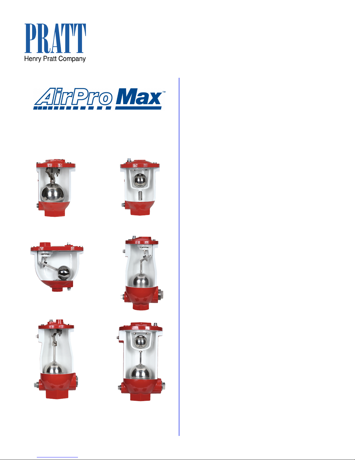
Series WAR Air Relesae Valve Series WAV Air Vacuum Valve Series WCV Combination Valve

AirPro Max™ Air Valves
Document #: APMAVOM Revision Date: 6/3/13
5
INSTALLATION
When AirPro Max ™air valves are delivered, immediately inspect for shipping damage to the con-
tainer/pallet and/or valve before receiving. After conrming the air valve(s) have no damage, the units
must all be stored out of the elements indoors (time > 6 months); or, “temporarily” under a water/
storm proof shed/roof/tarp. As soon as possible, install per the following minimum requirements:
• Vertical orientation only, valve cover vent on top. Use body casting letters as a reference.
• A stop/isolation valve should always be installed between pipeline and valve connection.
• All air valves should be located at a pipeline highpoint or per design engineering drawing.
• Valve must be placed where venting is available and can be protected. Avoid interfering with venting/
maintenance by any anti-vandalism or freezing /weather protection measures.
• Air valves discharge, or “spit”, slightly when closing depending on how fast they are lled. Pipe vent to
drain if valve is located in a plant. Discharge piping, snorkels or other vent outlet devices must not reduce
the outlet size of the air valve or allow for water collection at low points (unless low points are properly
drained).
OPERATION
All AirPro Max™ standard air valves operate automatically to remove pockets of air that build up in a pump/
piping system. All that needs to be done for startup is to open the recommended isolation valve (typically
provided by others). Venting will occur naturally and automatically with changes in pumping conditions until
isolation/shutdown is desired for maintenance, etc. To work on valve, simply shut off the isolation valve and
operation will cease until the isolation stop valve is again opened.
To avoid damage to system equipment and piping (due to air accumulation in line) - do not close the air valve’s
isolation valve and leave piping/pump system in normal operation for signicant duration (no longer than
absolutely necessary to perform valve maintenance). If valve is shut down and plant must maintain on-going
pumping for emergency purposes - Plant Manager written approval should be obtained prior to doing work -
with document to be posted at the valve station. (A red or Safety Orange warning sign should be also posted
on the air valve that indicates when (and for how long) it is OK for valve to be isolated and not in service.
WARNING
This manual suits for next models
5
Table of contents


