Henry Tools 45 Series Guide

The henry Tool Co., ManufaCTured by henry Tools
498 so. belvoir blvd., souTh euClid, oh 44121 u.s.a.
Ph: (216) 291-1011 or (800) 826-5257 ● Fax: (216) 291-5949 or (800) 303-2800
Email: da[email protected] ● WEbsitE: WWW.hEnrytools.com
General Safety and Maintenance Manual
Original Style
Tools Pre-Year 2009
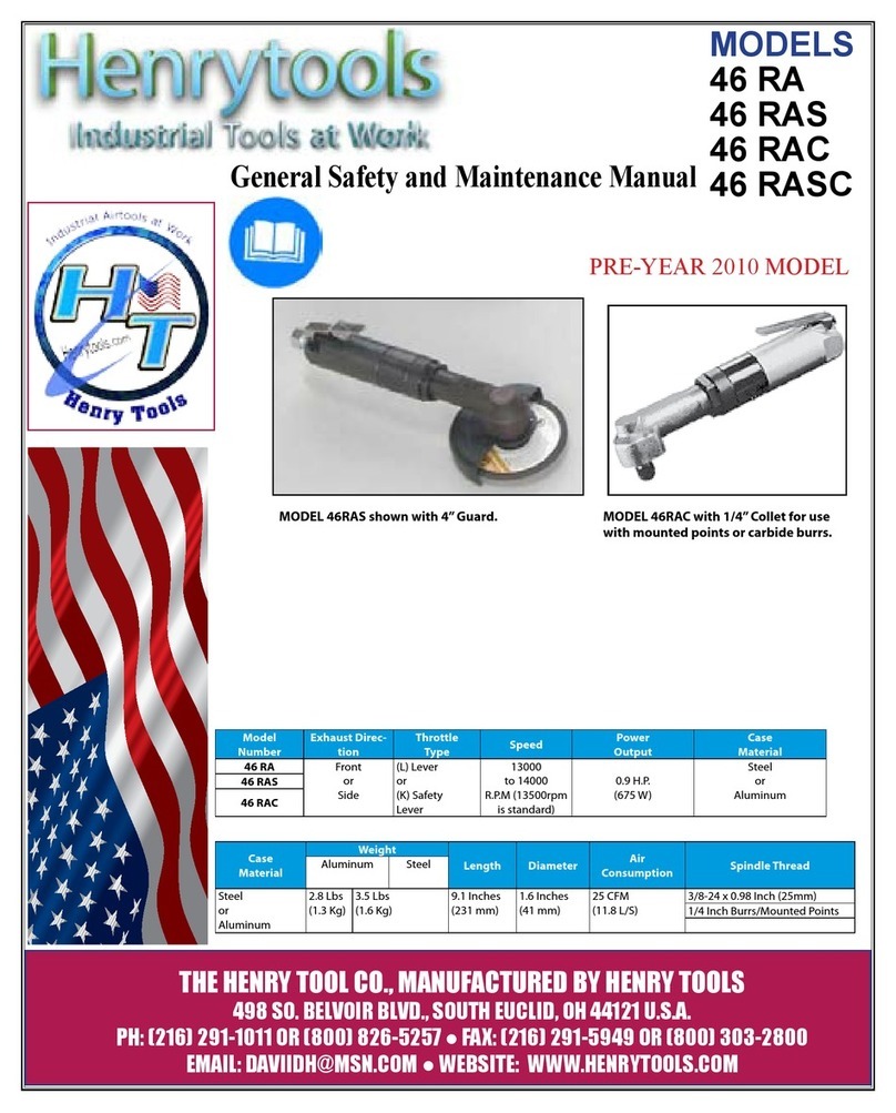
Model
Number
Exhaust
Direction
Throttle
Type
Speed Power
Output
Case
Material
Weight Length Diam-
eter
Air
Consumption
Spindle
Thread
Aluminum Steel
45RA
Side
(L) Lever
or
(K) Safety
Lever
12000
to 14000
R.P.M
(13500rpm
is standard)
0.9 H.P.
(675 W)
Steel
or
Alumi-
num
2 1/2 lbs
1.1kg
3.5 Lbs
(1.6
Kg)
8
5/16”-
211mm
1 3/4”
4.4cm
25 CFM
(11.8 L/S)
3/8-24 x
0.98 Inch
45RAZ 5/8-11 x
0.98 Inch
45RAS 3/8-24 x
0.98 Inch
45RAC
1/4 Inch
Built-In
Collet
Original Style
Tools Pre-Year 2009
MODELS
45 RA
45 RAC
45 RAZ
45 RAS
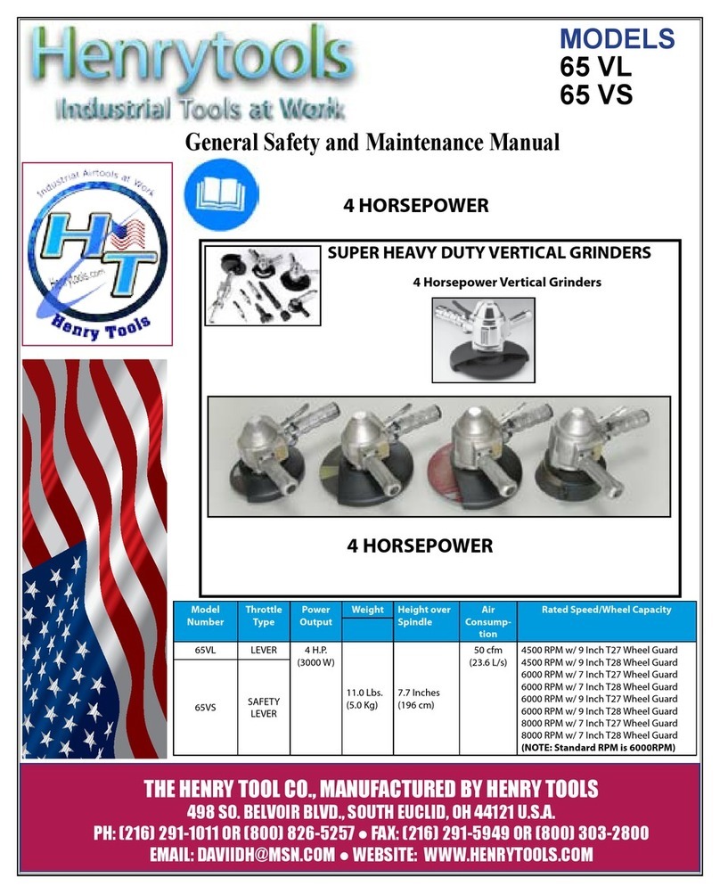
45 RA SERIES PNEUMATIC RIGHT ANGLE GRINDER

HENRY TOOLS, INC. Ph: (216) 291-1011 or (800) 826-5257
General Operators Instructions and Service Manual
www.HenryTools.com | Page 77 Revised 03/05/12
For additional product information visit our website.
Original Style
Tools Pre-Year 2009
PART NO. DESCRIPTION
400-G-11 FRONT BEARING
400-G-17 Alum Side Exhaust Sleeve
400-G-17-S Steel Side Exhaust Sleeve
400-G-4-GL Aluminum Backhead
400-G-4-GLS Steel Backhead
400-G-26 THROTTLE LEVER
400-G-34 SPRING
400-G-38 COLLET NUT
400-G-42 3/8-24 FLANGE (2”-3” WHEELS)
400-G-47 3/8-24 JAM NUT
400-2G CYLINDER WITH PIN INSTALLED
400-5 ROTOR
400-6 ROTOR BLADE (5 are required)
400-7 FRONT ENDPLATE
400-10 KEY
400-44 ROLL PIN
400-51 0-RING
402-126 SAFETY LEVER
402-127 SAFETY LEVER PIN
402-128 LOCKOUT LEVER
402-129 SAFETY LEVER SPRING
402-134 MUFFLER
404-1 ANGLE HEAD
404-2 BEARING CAP
PART NO. DESCRIPTION
404-3 UPPER OUTPUT SPINDLE BEARING
404-4 KEY
404-6 WAVY WASHERS(2 required)
404-7 LOWER SPINDLE BEARING
404-9 REAR MOTOR BEARING
404-14 SPINDLE
404-19 REAR ENDPLATE
404-20 MOTOR SPACER
404-38 BEARING COVER
404-39 SNAP RING
404-40 DEAD HANDLE
404-41 MOTOR CASE ALUMINUM
404-44 DEAD HANDLE OFFSET
405-5-625 5/8-11 X .980 OUTPUT SPINDLE
405-10 GEAR SET
405-15 GEAR SPACER SLEEVE
405-17 3/8-24 X .980 OUTPUT SPINDLE
540607 COLLET OUTPUT SPINDLE
405-17-5/8” 5/8-11 X .980 OUTPUT SPINDLE
500-G-44 3/8 ID FLANGE ( for 4”-5” WHEELS)
700-34 5/8-11 JAM NUT
700-37 THROTTLE LEVER PIN
1100-680 5/8 I.D. FLANGE
1100-682 “(6”” OR SMALLER WHEELS)
3/8 I.D. FLANGE”
591028 SCREW
591040 STAR WASHER
591048 BRACKET BOLT
591106 SET SCREW (SPECIFY SPEED)
592016 SNAP RING
594016 0-RING
832636 GASKET
841553 3/8 NPT TO 1/4 NPT BUSHING
844302 0-RING
869311 THROTTLE VALVE CAP
834782 THROTTLE VALVE-INCLUDES 844302
4503 3” TYPE 27 GUARD
4504 4” TYPE 27 GUARD
4505 5” TYPE 27 GUARD
490-3 PIN SPANNER
102-SPWR WRENCH FOR SANDING PAD NUT
1100-044 7/16” WRENCH
1100-050 1/2” WRENCH
MODELS
45 RA
45 RAC
45 RAZ
45 RAS

HENRY TOOLS, INC. Ph: (216) 291-1011 or (800) 826-5257
General Operators Instructions and Service Manual
www.HenryTools.com | Page 78 Revised 03/05/12
For additional product information visit our website.
Original Style
Tools Pre-Year
2009
PART NO. DESCRIPTION
1100-056 9/16” WRENCH
1100-063 5/8” WRENCH
1100-068 11/16” WRENCH
1100-075 3/4” WRENCH
1100-094 15/16” WRENCH
300-16 1/8” COLLET ADAPTER
400-78 3/8-24 TO 5/8-11 ADAPTER
405-24 BACKING PLATE FOR 490-KR
490-K 3/8-24 X .980 TYPE 27 ADAPTER
A S S Y.
490-KR 3/8-24 X .580 TYPE 27 ADAPTER
A S S Y.
490-1 BACKING PLATE FOR 490-K
490-2 NUT FOR 490-K & 490-KR
1100-660 3/8-24 TO 5/8 I.D. TYPE 27 ADAPTER
A S S Y.
1100-661 3/8-24 TO 5/8 I.D. BACKING PLATE
1100-662 3/8-24 TO 5/8 I.D. ADAPTER NUT
1100-664 3/8-24 TO 7/8 I.D. BACKING PLATE
1100-666 3/8-24 TO 7/8 I.D. ADAPTER NUT
1100-668 3/8-24 TO 7/8 I.D. TYPE 27 ADAPTER
A S S Y.
1100-692 5/8-11 TO 7/8 I.D. TYPE 27 ADAPTER
A S S Y.
1100-694 5/8-11 TO 7/8 I.D. BACKING PLATE
1100-696 5/8-11 TO 7/8 I.D. ADAPTER NUT
849259 5/8-11 SANDING PAD NUT
849259-A 3/8-24 SANDING PAD NUT
889271 5/8-11 4” SANDING PAD (MAX
12000 RPM)
889271-A 3/8-24 4” SANDING PAD (MAX
12000 RPM)
849848 5/8-11 5” SANDING PAD (MAX
10000 RPM)
849848-A 3/8-24 5” SANDING PAD (MAX
10000 RPM)
849913 5/8-11 7” SANDING PAD (MAX 8500
RPM)
849914 5/8-11 9” SANDING PAD (MAX 6500
RPM)
REPAIR KITS
510076 REPAIR KIT INCLUDES ALL BEAR-
ING, ROTOR BLADES, SNAP RINGS.
(WITH GEARS)
510078 REPAIR KIT INCLUDES ALL BEAR-
ING, ROTOR BLADES, SNAP RINGS.
(WITHOUT GEARS)
MODELS
45 RA
45 RAC
45 RAZ
45 RAS
PART NO. DESCRIPTION
ASSEMBLIES
402-26 SAFTETY LEVER ASSEMBLY
GRINDER SAFETY
ALWAYS COMPLY WITH:
1. General Industry Safety & Health Regulations, Part 1910, OSHA 2206, available from:
Sup’t of Documents; Government Printing Ofce; Washington DC 20402
2. Safety Code for Portable Air Tools, ANSI B186.1 available from: American National
Standards Institute, Inc.; 1430 Broadway; New York, NY 10018
3. State and Local regulations.
4. Portions of the above codes and regulations are listed below for quick reference.
THESE EXCERPTS ARE NOT INTENDED TO BE ALL INCLUSIVE - STUDY AND COMPLY WITH
ALL REGULATIONS!
1. Always turn off the air supply and disconnect the air supply hose before installing,
removing or adjusting any accessory on this tool, or before performing any maintenance on
this tool.
2. After mounting a wheel or other abrasive accessory, the Grinder shall be run in a
protected enclosure, at gradually increasing speed, for at least 60 seconds. When starting
work with a cold wheel, apply it gradually to the workpiece until it becomes warm. Do not
continue to use a grinder if:
• The speed rating of the accessory is less than the speed of the grinder
• If tool vibrates repair immediately.
• You sense changes in tool speed or an unusual increase in noise that would indicate
tool is running at excessive speed.
• You notice excessive end play in spindle
• You hear any unusual sound from grinder
RETURN THE TOOL TO THE TOOL CRIB FOR SERVICE IMMEDIATELY.
3. Make certain no one is in front of or in line with the wheel or other abrasive accessory.
Be aware that it may fail at this time if it is defective, improperly mounted or the wrong
size and speed. Stop immediately if considerable vibration or other defects are detected.
Shut off the air supply and determine the cause.
4. OPERATOR PROTECTIVE EQUIPMENT - Wear goggles or face shield at all times
tool is in operation. Other protective clothing shall be worn, if necessary. SEE REGULA-
TIONS.
5. Keep hands, loose clothing and long hair away from rotating end of tool.
6. Anticipate and be alert for sudden changes in motion during start up and operation of
any power tool.
7. Keep body stance balanced and rm. Do not overreach when operating this tool. High
reaction torques can occur at or below the recommended air pressure.
8. Tool accessories may continue to rotate briey after throttle is released.
9. Air powered tools can vibrate in use. Vibration, repetitive motions or uncomfortable
positions may be harmful to your hands and arms. Stop using any tool if discomfort, tin-
gling feeling or pain occurs. Seek medical advice before resuming use.
10. This tool is not designed for working in explosive atmospheres. Do not use this tool on
materials whose dust or fumes can cause a potentially explosive environment.
11. This tool is not insulated against electric shock.
12. Product Safety information - When Placing the Tool in Service
•NEVER MODIFY ANY PART OF THIS TOOL!!!! Always install, oper-
ate, inspect and maintain this product in accordance with all applicable standards and
regulations (local, state, country, federal, etc.).
• Always use clean, dry air at 90 psig (6.2 bar/620 kPa) maximum air pressure at the
inlet. Higher pressure may result in hazardous situations including excessive speed,
rupture, or incorrect output torque or force.
• Be sure all hoses and ttings are the correct size and are tightly secured.
• Install a properly sized Safety Air Fuse upstream of hose and use an anti-whip.
• Always turn off the air supply, bleed the air pressure and disconnect the air supply
hose before installing, removing or adjusting any accessory on this tool, or before per-
forming any maintenance on this tool or any accessory.
• Ensure that the grinding wheel or other abrasive accessory is correctly mounted and

HENRY TOOLS, INC. Ph: (216) 291-1011 or (800) 826-5257
General Operators Instructions and Service Manual
www.HenryTools.com | Page 79 Revised 03/05/12
For additional product information visit our website.
tightened before use.
• Always replace a damaged, bent or severely worn wheel guard.
Do not use a wheel guard that has been subjected to wheel failure.
• • Guard opening must face away from the operator. Bottom of
wheel must not project beyond guard.
•DO NOT MODIFY THE TOOL, SAFETY DEVICES, OR ACCES-
SORIES.
• Use accessories recommended by Henry tools.
• Do not use this tool if the actual free speed exceeds the rated rpm.
Check the free speed of the Grinder
before mounting a wheel, after all tool repairs, before each job and after
every 8 hours of use. Check speed with a calibrated tachometer, without
the abrasive product installed.
• Do not use any wheel or other abrasive accessory whose maximum
operating speed, as dened by its manufacturer, is less than the rated
speed of the Grinder.
• Inspect all grinding wheels for chips or cracks prior to mounting. Do
not use a wheel that is chipped, cracked or otherwise damaged.
• Inspect arbor, threads & clamping devices for damage & wear prior to
mounting wheel or other abrasive accessory.
• Do not use a grinding wheel that has been exposed to freezing tem-
peratures, extreme temperature changes, high humidity, solvents, water
or other liquids.
• Make certain grinding wheel or other abrasive accessory properly ts
the spindle. The wheel should not t too snugly or too loosely. Plain
hole wheels should have about .007” (0.17 mm) maximum diametral
clearance. Do not use reducing bushings to adapt a wheel to any arbor
unless such bushings are supplied by and recommended by the wheel
manufacturer.
• Always use the wheel anges furnished by the manufacturer and ap-
propriate for the wheel size and type.
Never use a makeshift ange or plain washer. Flanges should be in good
condition and free of nicks, burrs and sharp edges.
• Ensure that the thread type and size of the threaded abrasive product
exactly matches the thread type and size of the spindle.
• Prevent the spindle end from touching the bottom of the hole of cups,
cones or plugs with threaded holes, intended to be mounted on machine
spindles, by comparing dimensions and other relevant data for them.
• Do not use an unguarded grinder unless used for internal work and
only operated when the work offers protection.
Original Style
Tools Pre-Year
2009
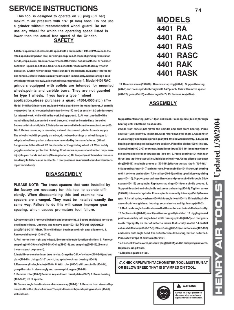
DISASSEMBLY
PLEASE NOTE: The brass spacers that were installed by the factory are
necessary for this tool to operate efciently. When disassembling this
tool examine how spacers are arranged. They must be installed exactly
the same way. Failure to do this will cause improper gear spacing, which
causes pre-mature tool failure.
1. Disconnect air & remove all wheels and accessories.
2. Remove dead handle (404-40). Secure anglehead vertically in vise
on dead handle boss. Never squeeze anglehead(404-1) in vise. This
will distort bearings and ruin gear alignment.
3. Unscrew backhead (400-G-4). Unscrew case (400-G-1).
4. Remove deector (400-G-17).
5. Pull motor from right angle head. Be careful to note location of
shims.
6. Remove snap ring (404-39),wafer(404-38),O-ring(594016), and
snap ring (592016).(Some of these parts may or maynot be present).
7. Install brass or aluminum jaws in vise. Grasp the O.D. of
cylinder(400-2-G) and end plate(404-19). Using a 3/16” punch, tap
spindle out rear bearing (404-9).
8. Remove cylinder, blades(400-6). 8. With rotor (400-5) still in
spindle (404-14), grasp the rotor in vise snugly and remove pinion
gear(405-10).
9. Remove rotor(400-5) Remove key and front thrust plate(400-7).
Press bearing (400-G-11) off of spindle.
10. Secure angle head in vise and unscrew cap (404-2).
11. Remove from vise and tap on spindle with a plastic hammer. The
spindle assembly and spring washers (404-6) will slide out.
12. Clamp ats of spindle(405-17) in vise.
MODELS
45 RA
45 RAC
45 RAZ
45 RAS
13. Using a 9/64” T-Handle hex wrench unscrew (591028) screw. Using a
plastic hammer tap on O.D. of bearing cap, until it is free of bearing(404-3).
Note positioN of shims.
14. Press bearing (404-3) off spindle. Support bearing (404-7) and
press spindle through with 1/4” punch. This will remove spacer (405-15),
gear(405-10) and bearing. Remove key (404-4).
ASSEMBLY
1. Support front bearing(400-G-11) on drill block. Press spindle (404-14)
through bearing until it bottoms on shoulder.
2. Slide front thrust(400-7)over the spindle and onto front bearing.
3. Place key(400-10) into keyway in spindle. Slide rotor down over shaft.
4. Grasp rotor in vise snugly and replace pinion gear(405-10) and wrench
rmly.
5. Support bearing and pinion gear in downward position. Place ve
blades(400-6) in slots. Slip cylinder(400-2-G) over rotor. Install rear
thrust(404-19) locating cylinder pin in small hole of rear thrust plate (404-
19).
6. Place bearing (404-9) in rear thrust and tap into place with a suitable
bearing driver. Using snap ring pliers, place snap ring(404-39) in end plate
groove.
7. Support bearing(404-7) on inner race. Press spindle (405-17) through
bearing until it bottoms on shoulder. Install key (404-4) and line up with
keyway of ring gear(405-10). Support gear on inner diameter and press
spindle through. Slide spacer(405-15) on spindle.
8. Support threaded end of spindle and press on bearing(404-3). Tighten
screw (591028) into end of spindle. Press spindle assembly into cap(404-2).
Grease gear.
9. Install spring washers(404-6) (rouNded side dowN) into angle head(404-
1).
10. Install spindle assembly into angle head housing, secure in vise and
tighten cap (404-2).
11. Re-Locate angle head in vise-so that the motor can be installed verti-
cally.
12. Replace shim(404-20) exactly as it was originally installed.
13. Jiggle greased pinion assembly into angle head while turning spindle
(405-17)-so that gears mesh. Tap lightly on rear of motor to insure that is
fully seated.
14. Install mufer (402-134) inside exhaust deector (400-G-17-S). Place
O-ring(400-51) on motor case(400-G-1), then slide case (400-G-1) over
motor assembly and screw onto anglehead(404-1). The deector (400-G-
17) should be snug, but can be turned. Place a few drops of oil into motor
inlet. Replace backhead assembly (400-G-4).
15. (optioNal step): To check throttle valve, unscrew plug(869311) and lift
out spring and valve. Replace O-ring if worn.
16. Replace guard on tool.
17. CHECK RPM WITH TACHOMETER.TOOL MUST RUN AT OR BELOW
SPEED THAT IS STAMPED ON TOOL.
This manual suits for next models
4
Table of contents
Other Henry Tools Grinder manuals
Popular Grinder manuals by other brands
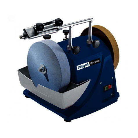
Scheppach
Scheppach TIGER2000S Assembly and operating instructions

Metabo
Metabo WXLA 24-180 Quick Original instructions

Hitachi Koki
Hitachi Koki G 10SR2 Safety instructions and instruction manual
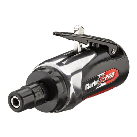
Clarke
Clarke CAT146 Operating & maintenance instructions

Arc-Zone
Arc-Zone Neutra LTG Operation manual

Makita
Makita 9553NB instruction manual


