Henry Tools 46 RA Guide

The henry Tool Co., ManufaCTured by henry Tools
498 so. belvoir blvd., souTh euClid, oh 44121 u.s.a.
Ph: (216) 291-1011 or (800) 826-5257 ● Fax: (216) 291-5949 or (800) 303-2800
Email: da[email protected] ● WEbsitE: WWW.hEnrytools.com
General Safety and Maintenance Manual
PRE-YEAR 2010 MODEL
Model
Number
Exhaust Direc-
tion
Throttle
Type Speed Power
Output
Case
Material
46 RA Front
or
Side
(L) Lever
or
(K) Safety
Lever
13000
to 14000
R.P.M (13500rpm
is standard)
0.9 H.P.
(675 W)
Steel
or
Aluminum
46 RAS
46 RAC
Case
Material
Weight
Length Diameter Air
Consumption Spindle Thread
Aluminum Steel
Steel
or
Aluminum
2.8 Lbs
(1.3 Kg)
3.5 Lbs
(1.6 Kg)
9.1 Inches
(231 mm)
1.6 Inches
(41 mm)
25 CFM
(11.8 L/S)
3/8-24 x 0.98 Inch (25mm)
1/4 Inch Burrs/Mounted Points
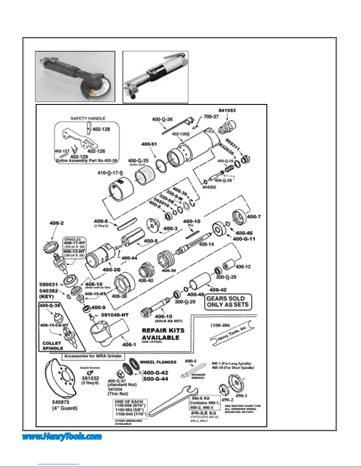
MODEL 46RAS shown with 4” Guard. MODEL 46RAC with 1/4” Collet for use
with mounted points or carbide burrs.
MODELS
46 RA
46 RAS
46 RAC
46 RASC
HENRY TOOLS, INC. Ph: (216) 291-1011 or (800) 826-5257
General Operators Instructions and Service Manual
www.HenryTools.com | Page 88 Revised 02/19/12
For additional product information visit our website.
PRE-YEAR 2010 MODEL
This tool is designed to operate
on 90 psig (6.2 bar) maximum
air pressure with 1/4” (8 mm)
hose. Do not use a grinder without
recommended wheel guard. Do
not use any wheel for which the
operating speed listed is lower
than the actual free speed of the
Grinder.
SAFETY
1. Before operation check
spindle speed with a tachometer.
If the RPM exceeds the rated
speed stamped on tool, servicing
is required.
2. Inspect grinding wheels for
bends, chips, nicks, cracks or
severe wear. If the wheel has any
of these, or has been soaked in
liquids do not use. On brushes
check for loose wires that may y
off in operation.
3. Start new grinding wheels
under a steel bench. Run at full
throttle for one minute. Defective
wheels usually come apart im-
mediately. When starting a cold
wheel apply to work slowly, allow
wheel to warm gradually.
4. Model 46RAC grinders
equipped with collets are intend-
ed for mounted wheels,points
and carbide burrs. They are
not guarded for type 1 wheels.
If you have a type 1 wheel
application,please purchase a
guard (540875).
5. The Model 46RA Grinders
are equipped with a guard from
the manufacturer. A guard is not
needed for :a.) mounted wheels
two inches (50 mm) or smaller;
b.) grinders used for internal
work, while within the work being
ground.
6. At least one-half of the
mandrel length (i.e. mounted
wheel, burr, etc.) must be
inserted into the collet. Secure
collet chuck tightly.
7. Safety levers are available
from the manufacturer.(402-26).
8. Before mounting or remov-
ing a wheel, disconnect grinder
from air supply. The wheel should
t properly on arbor, do not use
bushings or wheel anges to
adapt a wheel to any arbor un-
less recommended by the manu-
facturer. (Wheel anges should
be at least 1/3 the diameter of
the grinding wheel.)
9. Wear safety goggles and
other protective clothing. Con-
tinuous exposure to vibration
may cause injury to your hands
and arms.(See regulations.)
10. Properly maintained air
tools are less likely to fail or
cause accidents. If tool produces
an unusual sound or vibrations
MODELS
46 RA
46 RAS
46 RAC
46 RASC
HENRY TOOLS, INC. Ph: (216) 291-1011 or (800) 826-5257
General Operators Instructions and Service Manual
www.HenryTools.com | Page 89 Revised 02/19/12
For additional product information visit our website.
repair immediately.
11. NEVER MODIFY ANY PART OF THE TOOL OR ACCESSORIES!!
PART NUMBER DESCRIPTION
300-G-29 BEARING
320-9R O-RING CUSHION FOR BEARING COVER
320-9-W REAR BEARING COVER
400-G-11 FRONT BEARING
400-G-25 MUFFLER SCREEN
400-G-26 THROTTLE LEVER
400-G-29 THROTTLE VALVE-INCLUDES 844302
400-G-34 SPRING
400-G-38 COLLET NUT
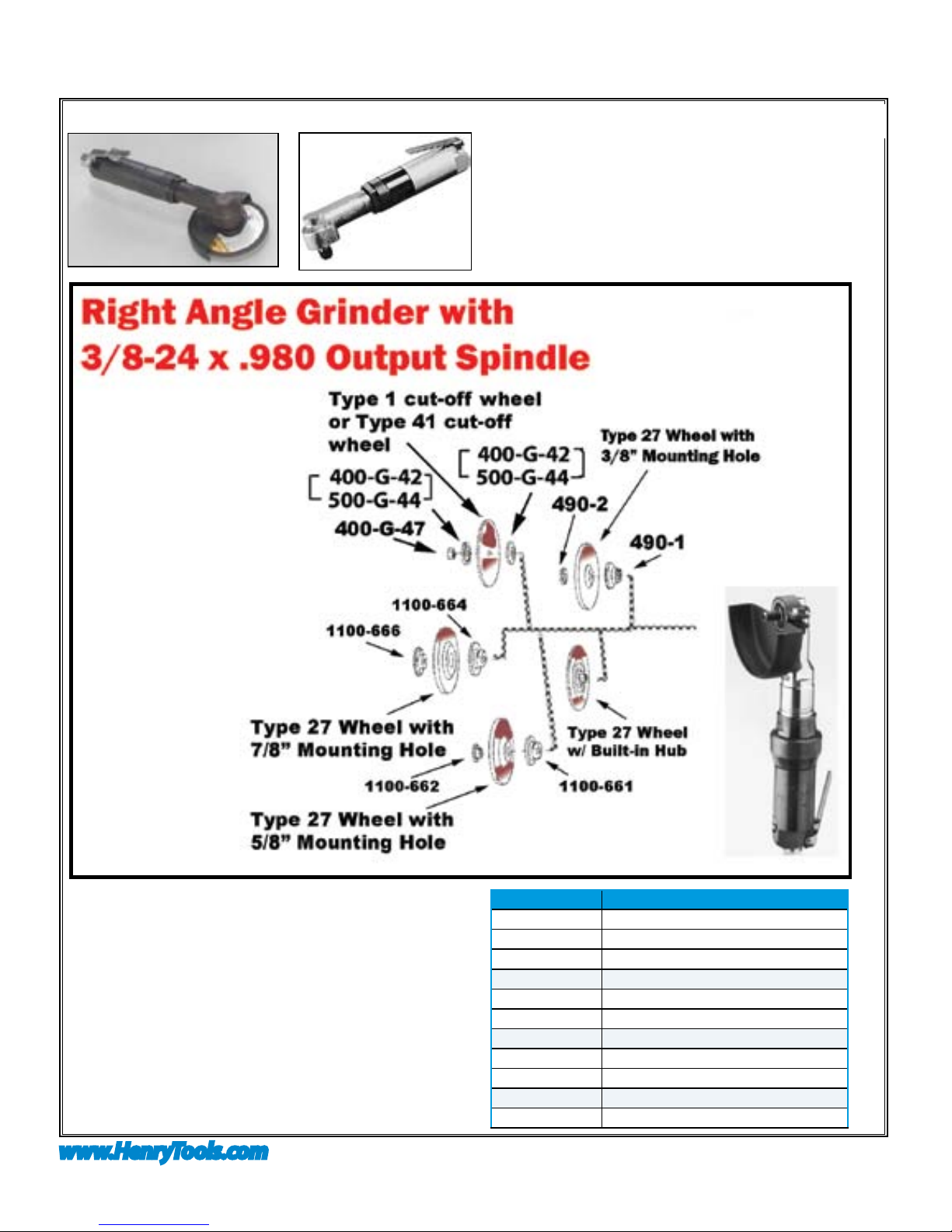
400-G-42 3/8-24 FLANGE (2”-3”WHEELS)
400-G-47 3/8-24 JAM NUT
SAFETY (continued)
MODELS
46 RA
46 RAS
46 RAC
46 RASC

HENRY TOOLS, INC. Ph: (216) 291-1011 or (800) 826-5257
General Operators Instructions and Service Manual
www.HenryTools.com | Page 90 Revised 02/19/12
For additional product information visit our website.
PART NUMBER DESCRIPTION
400-2G CYLINDER
400-3 REAR ENDPLATE
400-5 ROTOR
400-6 BLADE (5 ARE REQ.)
400-7 FRONT ENDPLATE
400-9 REAR OUTPUT BEARING
400-10 KEY
400-39 SNAP RING
400-44 CYLINDER ROLL PIN
400-46 SNAP RING
400-51 O-RING
402-126 SAFETY LEVER BARE
402-127 SAFETY LEVER PIN
402-128 LOCKOUT LEVER FOR SAFETY LEVER
402-129 SAFETY LEVER SPRING
402-130 ALUMINUM CASE (SPECIFY SPEED)
402-130-S STEEL CASE (SPECIFY SPEED)
406-1 (MAIN HEAD UNIT)BARE
406-2 LOCK RING
406-4 KEY
406-10 GEAR SET (SOLD AS SET)
406-13-HT 3/8-24 X .580 OUTPUT SPINDLE
406-14A MOTOR SPINDLE
406-15-HT GEAR SPACER
406-15-CS-HT COLLET OUTPUT SPINDLE
406-17-HT 3/8-24 X .980 OUTPUT SPINDLE
406-38 LOCKNUT
406-39 MOTOR RETAINER
406-40 HEAD RETAINER NUT
406-41 COUPLING
406-45 SNAP RING
406-61 MOTOR SPACER (THIN)
410-G-17F-S STEEL FRONT EXHAUST SLEEVE
410-G-17-S STEEL SIDE EXHAUST SLEEVE (STAN-
DARD)
500-G-44 3/8 ID FLANGE (4”-5”WHEELS)
700-37 THROTTLE LEVER PIN
1100-682 3/8 I.D. FLANGE FOR 5”-6”WHEELS
541034 THIN SPINDLE JAM NUT
590031 BEARING
591046-HT SCREW
591032 GUARD SCREW (3 are Required)
PART NUMBER DESCRIPTION
592016 SNAP RING
832636 GASKET
841552 3/8 NPT TO 3/8 NPT BUSHING
841553 3/8 NPT TO 1/4 NPT
BUSHING(STANDARD)
844302 O-RING
869311 THROTTLE VALVE CAP
GUARDS
540875 4”TYPE 27 GUARD
TOOLS /WRENCHES
490-3 PIN SPANNER
1100-044 7/16”WRENCH
1100-063 5/8”WRENCH
1100-068 WRENCH 11/16”
1100-075 WRENCH 3/4”
1100-094 15/16”WRENCH
REPAIR KITS
510118 REPAIR KIT WITHOUT GEAR SET( INCLUDES
BEARING,BLADES, ETC)(NOTE: GEAR SET
NOT INCLUDED.)
510119 REPAIR KIT WITH GEAR SET( INCLUDES
BEARING,BLADES, ETC)
ASSEMBLIES
402-26 SAFETY LOCKOUT LEVER ASSY. (COM-
PLETE)
AA-402-130 ALUMINUM CASE ASSY. SPECIFY SPEED
FOR CASE ASSY.
AA-402-130-K ALUMINUM SAFETY CASE ASSY. SPECIFY
SPEED FOR CASE ASSY.
AA-402-130-S STEEL CASE ASSY. SPECIFY SPEED FOR
CASE ASSY.
AA-402-130-SK STEEL SAFETY CASE ASSY. SPECIFY
SPEED FOR CASE ASSY.
ACCESSORIES
300-16 1/8” COLLET ADAPTER
400-78 3/8-24 TO 5/8-11 ADAPTER
405-24 BACKING PLATE FOR 490-KR
490-K 3/8-24 X .980 TYPE 27 ADAPT. ASSY.
490-KR 3/8-24 X .580 TYPE 27 ADAPT. ASSY.
490-1 BACKING PLATE FOR 490-K
490-2 NUT FOR 490-K & 490-KR
1100-660 3/8-24 TO 5/8 I.D. TYPE 27 ADAPTOR
ASSEMBLY
1100-661 3/8-24 TO 5/8 I.D. BACKING PLATE
MODELS
46 RA
46 RAS
46 RAC
46 RASC

HENRY TOOLS, INC. Ph: (216) 291-1011 or (800) 826-5257
General Operators Instructions and Service Manual
www.HenryTools.com | Page 91 Revised 02/19/12
For additional product information visit our website.
PRE-YEAR 2010 MODEL
PART NUMBER DESCRIPTION
1100-662 3/8-24 TO 5/8 I.D. ADAPTER NUT
1100-664 3/8-24 TO 7/8 I.D. BACKING PLATE
1100-666 3/8-24 TO 7/8 I.D. ADAPTER NUT
1100-668 3/8-24 TO 7/8 I.D. TYPE 27 //ADAPT.
ASSY.
530196 1/8” ROUNDED TAPER BURR
530198 1/8”TAPER BURR
530200 1/8” FLAME BURR
530202 1/8” BALL BURR
530204 1/8” CYLINDRICAL BURR
530208 1/4” BALL BURR
530210 1/4” CYLINDRICAL BURR
DISSASSEMBLY
1. Disconnect air & remove all wheels and accessories.
2. Secure tool vertically in vise. Clamp onto ats on back part of
backhead(402-130(S)).
3. Unscrew lock nut (406-38). Angle head will disconnect from motor
case. Being careful not to damage (406-1) head, remove coupling
(406-12), exhaust sleeve (410-G-17S), and exhaust screen (400-G-
25).
4. Unscrew and remove motor retainer (406-39). Pull motor out of
case.
5. Remove snap ring (400-39) and (592016).
6. Install brass jaws in vise, rmly grasp O.D. of cylinder (400-2G)
and end plate (400-3) in vise. Using a 3/16” punch tap spindle out of
rear bearing (400-9).
7. Remove cylinder, end plate, rotor (400-5), blades (400-6), key
(400-10) and front thrust (400-7).
8. Remove retaining ring (400-46). Press spindle (406-14) out of
bearing (400-G-11) with an arbor press or drill block.
9. Secure angle head in vise. Clamp on sides of output end. Remove
head retainer (406-40) using ats. Remove lock nut.
10.Remove lock ring (406-2) with lock ring tool. Remove angle head
assembly from vise.
11.Tap sides of angle housing to remove both spindle assemblies.
12.Remove screw (591046) from end of ring gear assembly.
13.Press bearing (400-9), (590031), spacer (406-5), ring gear (406-
10), and key (406-4) off spindle (406-17).
14.With pinion spindle (406-10) in hand-GEAR UP, tap end of gear
with plastic hammer until bearng (300-G-29) and spacer (406-42)
become free.
15.Remove retaining ring (400-46). Press gear spindle off of rear
bearing (300-G-29) with use of arbor press or drill block.
ASSEMBLY
1. Clean all parts before assembly.
2. Support bearing (400-G-11) on drill block. Press spindle (406-14)
through bearing until it bottoms on shoulder.
3. Place retaining ring (400-46) into groove in spindle.
Slide front thrust(400-7 over spindle and onto front bear-
ing.
4. Place key (400-10) into keyway in spindle.
5. Slide rotor (400-5) over spindle. Place (400-6) blades
in slots.
6. Slip cylinder (400-2G) over rotor. Install rear thrust
(400-3) locating cylinder pin in smaller hole of the rear
thrust plate.(400-3)
7. Place bearing (400-9) in rear thrust & tap in place
with a suitable bearing driver. Using pliers place snap ring
(592016) in spindle groove. Replace bearing cover if pres-
ent. Replace snap rings (400-39).
8. Secure case(402-130) in vise vertically. Slip motor as-
sembly into case. Install O-ring (400-51), exhaust screen
(400-G-25), and exhaust deector (410-G-17-S).
9. Screw motor retainer (406-39) into end of case and-
tighten.
10. Press bearing (300-G-29) on gear spindle (406-
10) with arbor press. Replace retaining ring (400-46) in
groove of spindle.
11. Press spacer (406-42) and bearing (300-G-29) onto
gear spindle with arbor press.
12. Press bearing (590031) onto spindle (406-17) or
(406-13).
13. Place key (540382) in slot of spindle.
14. Align keyway in ring gear (406-10) with key in spindle
and press together with an arbor press.
15. Place spacer (406-15) and bearing (400-9) over end
of spindle. Press in place with arbor press. Thread screw
(591046) in end of spindle.
16. Place this angle assembly into housing (406-1). Re-
place lock ring (406-2) with lock ring tool.
17. Place (406-38) over end of housing. Replace bearing
(300-G-29) on gear. Place (406-2) over Gear spindle.
Replace the other (300-G-29) bearing onto end of gear
spindle. Slide this assembly into head (406-1). Thread on
retainer (406-40) and tighten.
18. Place coupling (406-12) on spline on end of motor
spindle.
19. Place angle head onto end of motor housing. Align
splines inside coupler. Tighten lock nut on motor case and
run tool.
20. Replace guard on tool.
21. Check RPM with a reliable tachometer. Tool must run
at or below speed stamped or marked on tool.
MODELS
46 RA
46 RAS
46 RAC
46 RASC
This manual suits for next models
3
Other Henry Tools Grinder manuals


