HENRY TOOLS, INC. Ph: (216) 291-1011 or (800) 826-5257
General Operators Instructions and Service Manual
www.HenryTools.com | Page 176 Revised 02/19/12
For additional product information visit our website.
• This tool is not designed for working in explosive environ-
ments, including those caused by fumes and dust, or near
ammable materials.
• This tool is not insulated against electric shock.
• Be aware of buried, hidden or other hazards in your work
environment. Do not contact or damage cords, conduits, pipes
or hoses that may contain electrical wires, explosive gases or
harmful liquids.
• Keep hands, loose clothing, long hair and jewelry away from
working end of tool.
• Power tools can vibrate in use. Vibration, repetitive motions
or uncomfortable positions may be harmful to your hands and
arms. Stop using any tool if discomfort, tingling feeling or pain
occurs. Seek medical advice before resuming use.
• Keep body stance balanced and rm. Do not overreach when
operating this tool. Anticipate and be alert
for sudden changes in motion, reaction torques, or forces dur-
ing start up and operation.
• Tool and/or accessories may briey continue their motion
after throttle is released.
• To avoid accidental starting - ensure tool is in “off” position
before applying air pressure, avoid throttle
when carrying, and release throttle with loss of air.
• Ensure work pieces are secure. Use clamps or vises to hold
work piece whenever possible.
• Do not carry or drag the tool by the hose.
• Do not use power tools when tired, or under the inuence of
medication, drugs, or alcohol.
• Never use a damaged or malfunctioning tool or accessory.
• Do not modify the tool, safety devices, or accessories.
• Do not use this tool for purposes other than those recom-
mended.
• Use accessories recommended by Ingersoll-Rand.
• Do not use this tool if the actual free speed exceeds the
rated rpm. Check the free speed of the Grinder before mount-
ing a wheel, after all tool repairs, before each job and after
every 8 hours of use. Check
speed with a calibrated tachometer, without the abrasive
product installed.
• Do not use any wheel or other abrasive accessory whose
maximum operating speed, as dened by its manufacturer, is
less than the rated speed of the Grinder.
• Inspect all grinding wheels for chips or cracks prior to
mounting. Do not use a wheel that is chipped,
cracked or otherwise damaged.
• Inspect arbor, threads & clamping devices for damage &
wear prior to mounting wheel or other abrasive accessory.
• Do not use a grinding wheel that has been exposed to freez-
ing temperatures, extreme temperature
changes, high humidity, solvents, water or other liquids.
• Make certain grinding wheel or other abrasive accessory
properly ts the spindle. The wheel should not t too snugly or
too loosely. Plain hole wheels should have about .007” (0.17
mm) maximum diametral
clearance. Do not use reducing bushings to adapt a wheel to
any arbor unless such bushings are supplied by and recom-
mended by the wheel manufacturer.
• Blotters shall always be used between anges and abrasive
wheel surfaces to ensure uniform distribution of ange pres-
sure (except type 27 & 28 wheels) and shall cover the entire
contact area of the wheel ange.
• Always use the wheel anges furnished by the manufacturer
and appropriate for the wheel size and type.
Never use a makeshift ange or plain washer. Flanges should be in good
condition and free of nicks, burrs and sharp edges.
• Ensure that the thread type and size of the threaded abrasive product
exactly matches the thread type and size of the spindle.
• Prevent the spindle end from touching the bottom of the hole of cups,
cones or plugs with threaded holes, intended to be mounted on machine
spindles, by comparing dimensions and other relevant data for them.
• Ensure that the grinding wheel or other abrasive accessory is correctly
mounted and tightened before use.
• Before starting this tool, the operator shall make sure that no one is in
the plane of rotation.
• Wear Personal Protective Equipment and remove ammable objects
from the work area to ensure that sparks and debris do not create a
hazard when using this tool.
• After mounting a wheel or other abrasive accessory, the Grinder shall
be run in a protected enclosure, at gradually increasing speed, for at
least 60 seconds. Make certain no one is in front of or in line with the
wheel or other abrasive accessory. Be aware that it may fail at this time
if it is defective, improperly mounted or the wrong size and speed. Stop
immediately if considerable vibration or other defects are detected. Shut
off the air supply and determine the cause.
• Do not use this tool on materials whose dust or fumes can cause a
potentially explosive environment.
• When starting a cold wheel, apply it to the work slowly until the wheel
gradually warms up. Make smooth contact with the work, and avoid any
bumping action or excessive pressure.
• If the grinder is dropped or bumped, turn off the air supply and care-
fully examine the grinding wheel or other abrasive accessory. Discard it if
damaged, chipped or cracked. Before reuse, run the grinder in a protect-
ed enclosure following the same precautions used after rst mounting.
• Before a grinder is put down, the throttle shall be released and the
wheel or other accessory shall come to a stop. Tool rests, hangers, and
balancers are recommended.
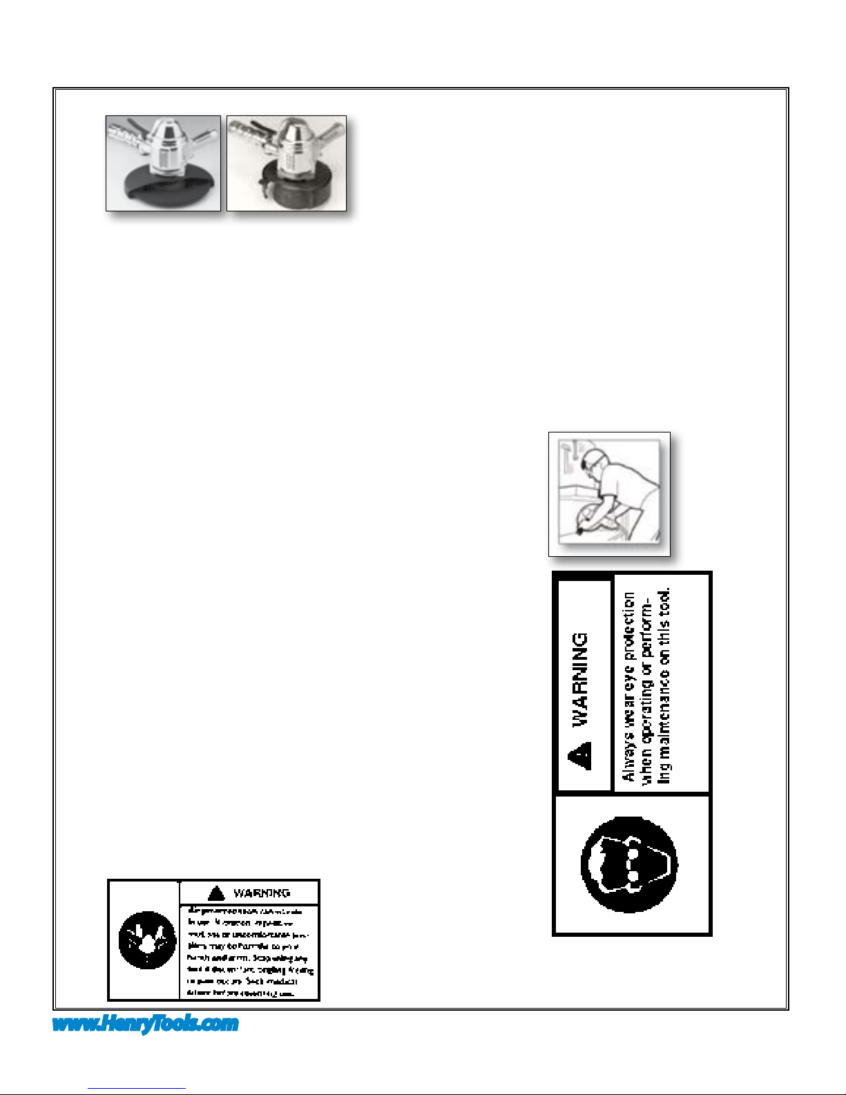
Additional Warnings for Guarded Grinders
• Do not use this Grinder without the furnished Wheel Guard.
• Incorrect combinations of grinder wheel, wheel guard and tool speed
could result in injury. Ensure that combinations are correct per the Prod-
uct Specications.
• Always replace a damaged, bent or severely worn wheel guard. Do not
use a wheel guard that has been subjected to wheel failure.
• Guard opening must face away from the operator. Bottom of wheel
must not project beyond guard.
Additional Warnings for Unguarded Grinders
• Do not use an unguarded grinder unless used for internal work and only
operated when the work offers protection.dditional Warnings for Use of
Cut-off Wheels (Type 1 and 27A)
• When cutting, support the workpiece so the slot is kept at constant or
increasing width during the whole operation.
• If the abrasive product gets jammed in a cut slot, shut off the grinder
and ease the wheel free. Check that the wheel is still correctly secured
and not damaged before continuing the operation.
• A cut-off wheel shall NOT be used for side grinding.
PRODUCT SAFETY INFORMATION WHEN
USING THE TOOL:CONTINUED
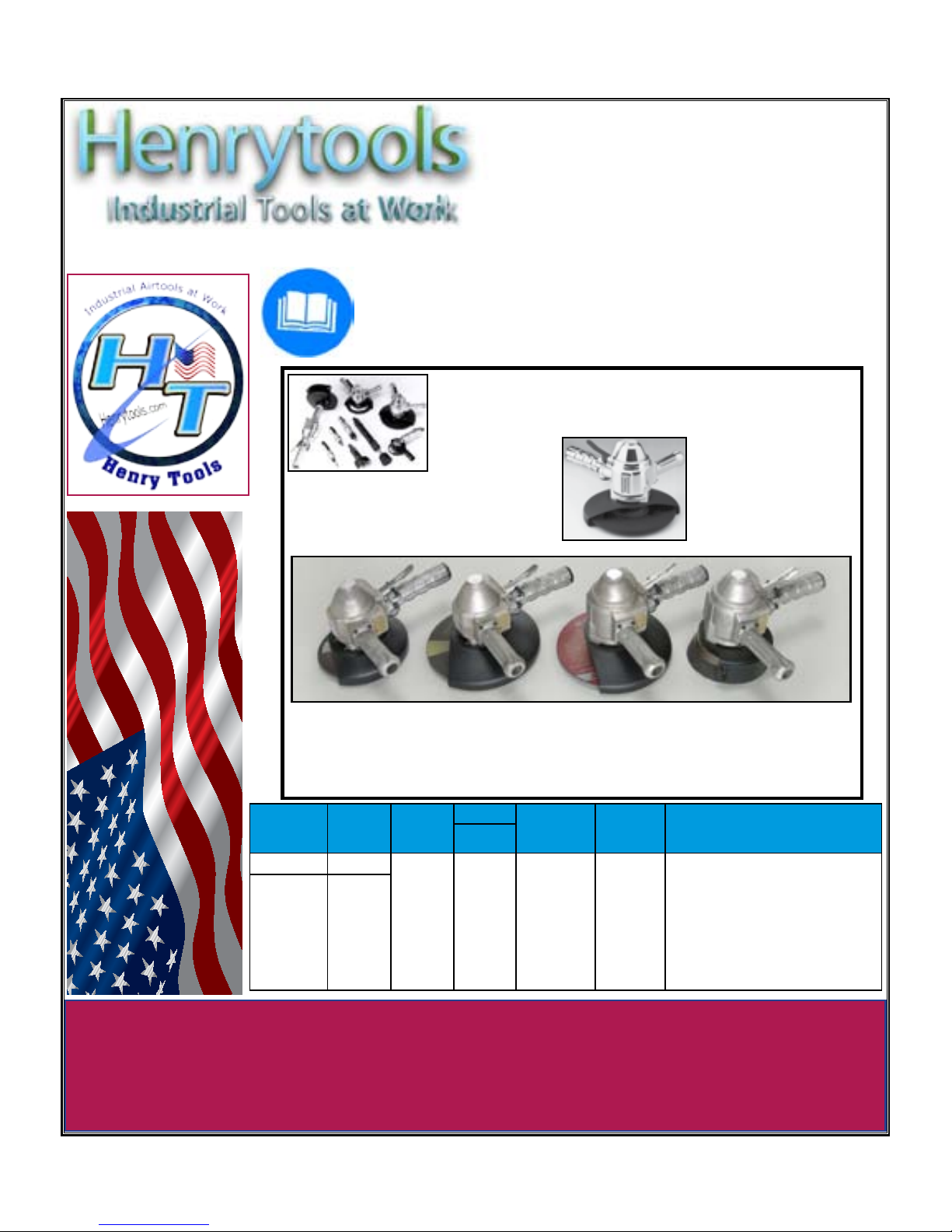
MODELS
65 VL
65 VS