HENRY TOOLS, INC. Ph: (216) 291-1011 or (800) 826-5257
General Operators Instructions and Service Manual
www.HenryTools.com | Page 122 Revised 06/25/12
For additional product information visit our website.
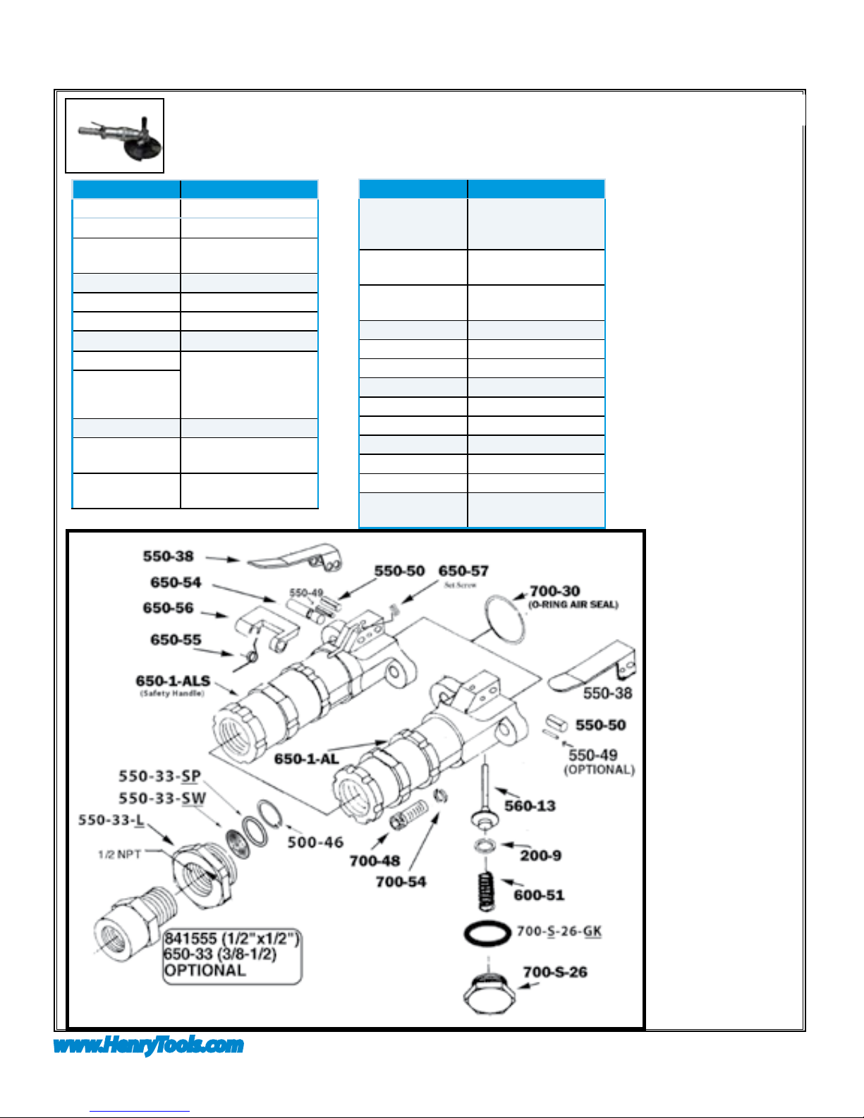
Disassembly
1. Remove grinding wheels. Disconnect tool from
air supply. Remove spindle lock assembly (AA-
NRA-20).
2. Secure the tool in vise vertically with the angle
head (NRA-1) toward downward direction. Clamp
lightly onto dead handle boss on the side of angle
head. Using a wrench on ats of live handle,
unscrew motor housing from angle head. Remove
motor from case or angle head.
motor Disassembly
1. Place brass jaws on vice. Secure pinion gear
(NRA-10) in vise and remove governor (NGOV-XX).
Note: (Left-hand thread).
2. Clamp motor assembly into vise with output
pointed down. Clamp lightly onto the cylinder (N2)
and rear endplate (NV-3). Place a small punch into
the center of the motor spindle (NRB-5) where the
governor was removed. Tap lightly on end of punch
with a small hammer. This will drive the spindle
through the rear bearing (NV-9) (Be sure not to
damage threads on the rear of the spindle.) (DO
Not DROP spindle assembly when it becomes free.)
Remove everything from vise.
3. Remove rear bearing from rear endplate (NV-3)
with a suitable punch or screwdriver. Remove rotor
blades (N6) from rotor.
4. Place brass jaws on vise. Clamp front spindle as-
sembly in vise vertically with output in upward
direction. Clamp onto the large outside diameter
of the rotor. Remove pinion gear (NRA-10) with a
wrench. Remove assembly from vise.
5. Press output end of spindle through front bearing
(NRA-8) with an arbor press. Remove front bearing
support (NRA-8).
the angle heaD Disassembly
1. Remove snap ring (NRA-14) using snap ring pliers.
Remove spacer (NRA-13) and o-ring (594030). Lift
output spindle assembly from angle head.
2. Place brass jaws on vise. Clamp rmly onto threads
of output assembly. Unscrew and remove screw
(591164) from end of spindle. Remove from vise.
3. Support the spindle assembly vertically on a suit-
able drill block supporting under the rear bearing
(NRA-9). Press spindle out of rear bearing.
4. Slide the gear spacer (NRA-15) off rear of spindle.
5. Support the spindle assembly vertically on a suit-
able drill block. Press spindle through ring gear
(NRA-10). Grasp key (NRA-43) and remove from
key slot.
6. Support the spindle assembly vertically on a suit-
able drill block. Press spindle through front bearing
(NRA-16).
assembly
1. Make sure all parts are clean.
THE MOTOR REASSEMBLY
1. Place the front endplate (NRA-7) over the rotor
(NRB-5). (The recessed side of the endplate faces
the output of the motor assembly.)
2. Support the assembly with the output end up on a
suitable drill block. Press the bearing (NRA-8) onto
the shaft and up to the rotor.
3. Place brass jaws onto vise. Clamp front spindle assembly in vise
vertically with output in upward direction. Clamp onto the large out-
side diameter of the rotor. Thread on and tighten the pinion gear
(NRA-10) with a wrench. Remove assembly from vise.
4. With brass jaws still in vise, clamp motor assembly into vise verti-
cally with output down. Clamp onto the sides of the pinion gear.
5. Place four blades (N6) into blade slots of rotor. Place the cylinder
(N2) over the spindle/rotor with the locating pin pointing away from
the pinion gear.
6. Place the rear endplate (NV-3) onto the end of the cylinder. (Align
the smaller hole of the endplate over the pin on the cylinder.)
7. Place the rear bearing (NV-9) over the governor stem of the spindle
and drive into place with a suitable bearing driver.
8. Prior to reassembly inspect governor for gouges, nicks or dents.
Thread on and tighten the governor with a wrench (LEFT hand
thread). Remove assembly from vise.
the angle heaD reassembly
1. Support the bearing (NRA-16) on a suitable drill block.
2. Press the spindle (NRA17{A}) through bearing until it bottoms on
shoulder.
3. Install the key (NRA-43) into the key slot of the spindle.
4. Place the ring gear (NRA-10) over the spindle and key. Align the
key with the keyway of ring gear.
5. Support the spindle assembly vertically on a suitable drill block with
output toward downward direction.
6. Press the ring gear over the key and up to front bearing. (Take care
not to damage the teeth of the gear.)
7. Slide spacer (NRA-15) onto spindle.
8. Support the spindle assembly vertically on a suitable drill block with
output toward downward direction.
9. Press the rear bearing (404-3) onto end of spindle.
10. With brass jaws in vise, secure spindle assembly into vise vertically
with output toward downward direction. Clamp onto the threads of
the angle spindle.
11. Screw in and tighten screw (591164) into end of spindle. Remove
from vise.
12. Grease gear teeth with a lithium soap based, NGLI grade 2 grease.
13. Slide the spindle assembly into right angle head (NRA-1).
14. Install o-ring (594030) and spacer (NRA-13) in front of angle head.
Install snap ring (NRA-14) into groove in angle head housing.
Final stage reassembly
1. Install o-ring (594228) onto motor housing (NRA-130). Lightly oil
o-ring. Install exhaust deector (NRA-27A) onto motor housing.
2. Assemble live handle. Bolt live handle onto motor housing with 4
screws (550-48) and lockwashers (550-54).
3. Secure angle head assembly in vise with motor opening toward
upward direction. Clamp lightly onto the dead handle boss.
4. Install motor assembly onto angle head. Jiggle assembly until gears
align. Turning the output spindle will aid gear mesh.
5. Slide motor housing over motor assembly and tighten onto threads
of right angle head, using ats on live handle.
6. Install spindle lock assembly (AA-NRA-20). Replace guard on tool.
7. Check RPM with a reliable tachometer. Tool must run at or below
speed stamped on tool.
8. NEVER MODIFY ANY PART OF THIS TOOL AND
ITS ACCESSORIES!!! Serious injury can result.
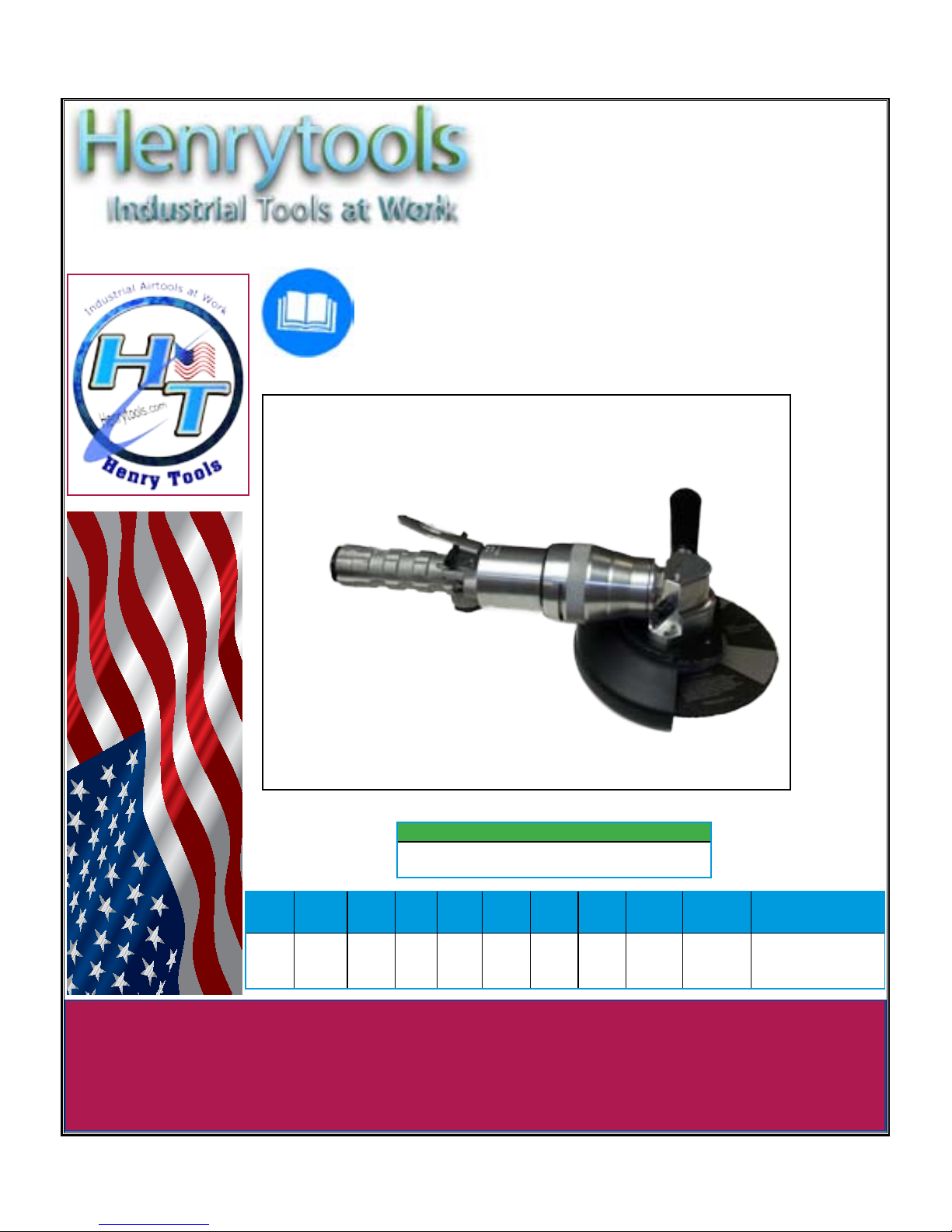
MODELS
52 RA