Hep2O 52UH873 User manual

Model: 52UH873
Video
Twitter: hep2o
Facebook:
facebook.com/hep2o
PDF FAQ
Heating Professionals:
Request a copy of our product installation
guide for our complete product range:
www.hep2o.co.uk
Want More Information?
Call our support team on: 0844 856 5152/3
Or visit our website: www.hep2o.co.uk
H
R
g
w
W
a
n
t
M
o
r
e
I
n
f
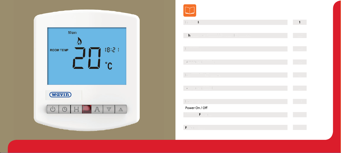
Table of Contents
1
2
3-4
5-6
7-8
9
10
11-12
13
14
15
16
17
18
19-22
23
24
25-29
11
1
3
1
3
7
-
87
-
8
1717
3
-4
3
-4
1515
1010
1
9
-
2
1
9
-
222
Product Image
Table of Contents
What is a Programmable Room Thermostat?
Installation Procedure
LCD Display
Setting the Clock
Temperature Display
Setting the Comfort Levels
Locking the Thermostat
Setting the Temperature
Temperature Hold
Holiday Programming
Frost Protection
Optional Features
Re-calibrating the Thermostat
Factory Reset
Wiring Diagrams
PP
rr
oduodu
cc
tt
II
magemage
LL
o
c
o
c
kk
i
n
g
i
n
g
t
he
t
he
TT
h
e
h
e
rr
m
ost
m
ost
aa
tt
LL
C
D D
C
D Dis
pl
is
pl
aa
yy
FF
rr
o
s
t
o
s
t
PP
rr
oo
tt
ee
cc
ti
o
nti
o
n
WW
hh
aa
t
ist
is
a
a
PP
rr
oo
gg
rr
a
mm
aa
mm
able
ble
RR
oomoom
TT
hehe
rr
mostmost
aa
t?t?
TT
empeempe
TT
TT
rara
tutu
rr
e
H
oe
H
o
l
d
l
d
TT
empeempe
TT
TT
rara
tutu
rr
e
Di
e
Disp
l
sp
l
aa
yy
O
pti
O
ptiona
l
ona
l
FF
ee
aa
tutu
rr
eses
2
4
2
4
FF
aa
cc
tt
oo
rr
y
y
RR
e
se
te
se
t
2Slimline Series1

43 Slimline Series
The best way to do this is to set the room thermostat to a low temperature
– say 18°C , and then turn it up by 1°C each day until you are comfortable with the
temperature. You won’t have to adjust the thermostat further. Any adjustment above
this setting will waste energy and cost you more money.
If your heating system is a boiler with radiators, there will usually be only one
programmable room thermostat to control the whole house. But you can have
(TRVs) on individual radiators.
If you don’t have TRVs, you should choose a temperature that is reasonable for the
whole house. If you do have TRVs, you can choose a slightly higher setting to make
sure that even the coldest room is comfortable, then prevent any overheating in other
rooms by adjusting the TRVs.
You are able to temporarily adjust the heating program by overriding or using the
temperature hold feature. These features are explained further on pages 14 and 15 of
this manual.
so they must not be covered by curtains or blocked by furniture. Nearby electric
properly.
What is a Programmable Room Thermostat?
A programmable room thermostat is both a programmer and a room thermostat.
The room thermostat works by sensing the air temperature, switching on the heating
this set temperature has been reached.
So a programmable room thermostat lets you choose what times you want the heating
to be on, and what temperature it should reach while it is on. It will allow you to select
to meet your particular needs and preferences.
Setting a programmable room thermostat to a higher temperature will not make the
room heat up any faster. How quickly the room heats up depends on the design & size
of the heating system.
down. Setting a programmable room thermostat to a lower temperature will result in the
room being controlled at a lower temperature, and saves energy.
chosen, and then leave it alone to do its job.
65 Slimline Series
1
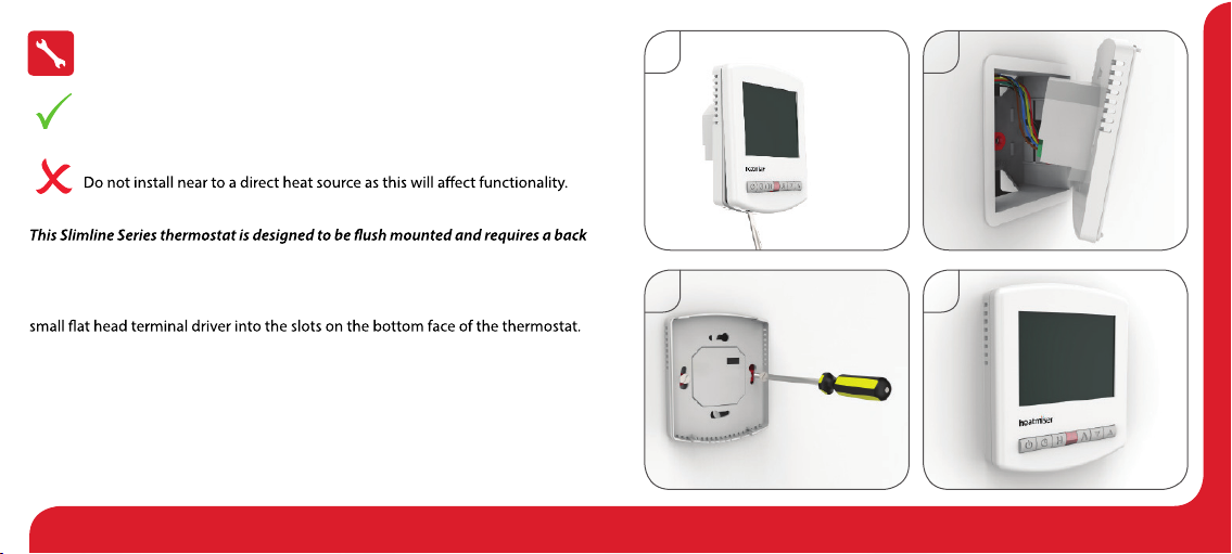
Installation Procedure
box of 35mm (minimum depth) to be sunk into the wall prior to installation.
Step 1
Carefully separate the front half of the thermostat from the back plate by placing a
Step 2
Place the thermostat front somewhere safe.
Terminate the thermostat as shown in the diagrams on pages 25-29 of this booklet.
Step 3
Screw the thermostat back plate securely into the back box.
Step 4
Clip the front of the thermostat back onto the thermostat back plate.
Do
Mount the thermostat at eye level.
Read the instructions fully so you get the best from our product.
Don’t
Do not push hard on the LCD screen as this may cause irreparable damage.
2
3 4
87 Slimline Series
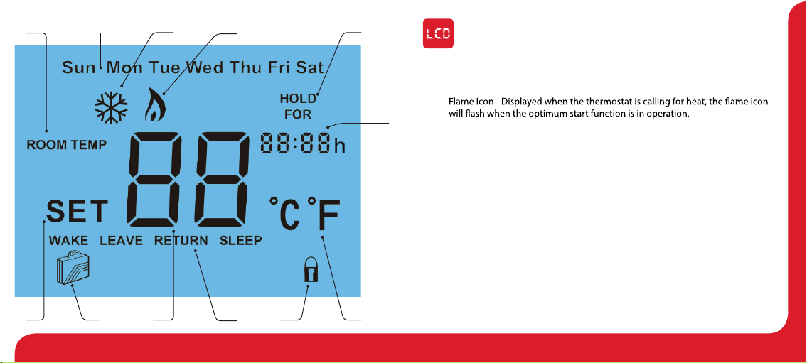
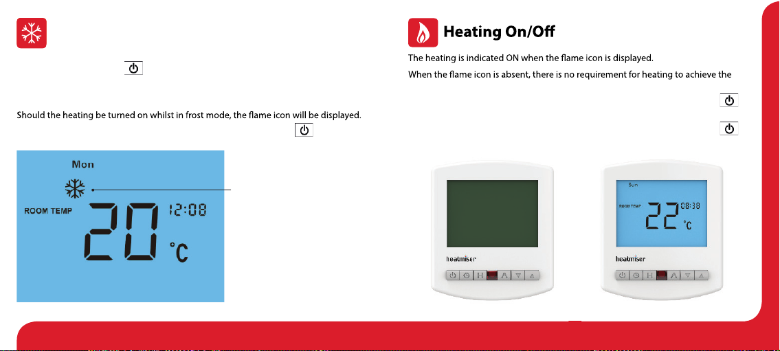
1. Room Temp - Indicates the current temperature sensor mode.
2. Day Indicator - Displays the current day.
3. Frost Icon - Displayed when the thermostat is in frost protection mode.
4.
5. Temperature Hold - When a Temp Hold is active, HOLD FOR and the remaining
time period is displayed.
6. Set - Indicates when changes are being made to programs or temperature set
points.
7. Holiday Indicator - Displayed when the thermostat is in holiday mode.
8. Current Temp - Indicates the current sensor temperature.
9. Program Cycle Indicator - Displayed during programming only to show which
period is being altered.
10. Keypad Lock Indicator - Displayed when the keypad is locked.
11. Units of Temperature - Degrees Celsius or Fahrenheit.
12. Clock - Digital clock display in 24h format.
LCD Display
12
345
678 91011
12
109 Slimline Series
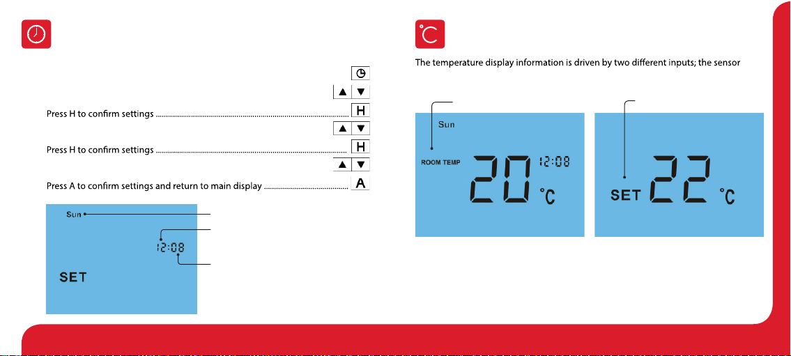
Setting the Clock
To set the clock, follow these steps.
t With the thermostat turned ON, press the Clock key twice .................................
t Use the Up/Down keys to set the hours ..............................................................
t
t Use the Up/Down keys to set the minutes .........................................................
t
t Use the Up/Down keys to set the day of the week ..........................................
t
Temperature Display
Day
Hours
Minutes
Room Temperature Set Temperature
This is the current room temperature. This is the temperature you are trying to
achieve in your home.
measurement and the target temperature you have set.

1211 Slimline Series
Comfort Levels Explained
The thermostat provides Weekday/Weekend or 7 Day Programming options.
You should consult the “Optional Features”section to select the required mode.
The thermostat is supplied with comfort levels already programmed, but these can be
changed easily. The default times and temperatures are;
08.00 - 21°C (Wake) 09.30 - 16°C (Leave) 16.30 - 22°C (Return) 23.00 - 17°C (Sleep)
If you only want to use 2 levels, you should program the unused levels to --.--
Note: For Weekday/Weekend programming, the 4 comfort levels are the same for all
t To program comfort levels, press Clock once ...................................................................
t Use the Up/Down keys to enter the required WAKE time .......................
t
t Use the Up/Down keys to enter the required WAKE temperature .......
t
t You will now see “LEAVE” displayed on screen.
t Repeat the programming steps for each period until complete.
t For unused periods enter --.-- and the thermostat will ignore the setting.
t
Note:
t In 7 Day programming mode you can repeat for each day independently.
t In Weekday/Weekend programming mode you will see Sat Sun displayed on
screen and can repeat for the weekend.
t To change the programming mode please refer to pages 20-22.
For 7 Day programming,
only Mon is displayed
For Weekday/Weekend programming,
Mon Tue Wed Thu Fri
are displayed on screen.

1413 Slimline Series
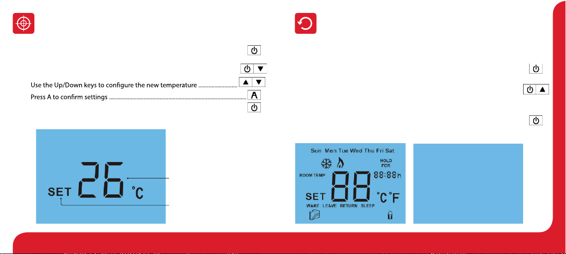
Temperature Control
The Up/Down keys allow you to adjust the set temperature .......................
When you press either key, you will see the word SET and the desired
temperature will be displayed on screen.
Use the Up/Down keys to adjust the SET value ..................................................
Press A to and return to main display .............................................
Set Temperature
Set Icon
Locking the Thermostat
The thermostat has a keypad lock facility. To activate the lock follow these steps.
t Press and hold the A and Down keys together for 10 seconds ..........
t You will see the lock symbol appear on screen .............................................
t To unlock, repeat the steps above until the lock symbol disappears.
..
Note: The keypad lock indicator is only displayed when the lock is active.
Note: This override will be maintained until the next programmed comfort level.
Keypad Lock Indicator

1615 Slimline Series
Holiday
Holiday Days
Holiday ON Indicator
Temperature Hold
The temperature hold function allows you to manually override the current operating
t Press H to commence temperature hold ...................................................................
t Use the Up/Down keys to enter the required hold time..............................
t
t Use the Up/Down keys to enter the required hold temperature..............
t
You will see the Hold For indication is displayed on screen.
The time will countdown the set duration and then revert to the normal program.
To cancel temperature hold, follow the same steps but reduce the Hold time to 00:00 hours.
Hold ON Indicator
Hold Time Remaining
Note: A holiday period does not start until 00:00 the next day. For example, if you set
thermostat will revert back to the programmed schedule at 00:00 on Monday.
The holiday function reduces the set temperature in your home to the frost
protection temperature setting (see page 19).
The thermostat will maintain this temperature for the duration of the holiday and will
then automatically return to the program mode on your return.
t Press H three times (until you see the suitcase on screen) .................................
t Use the Up/Down keys to enter the number of days holiday ...................
t
The display will show a suitcase indicating the thermostat is in holiday mode.
To cancel, follow the same steps but reduce the Holiday duration to 00 days.
Thermostat completely OFF Thermostat powered ON
1817 Slimline Series
Pressing the Power button once will place the thermostat in frost protect mode.
In this mode, the thermostat will display the frost icon and will only turn the heating
on should the room temperature drop below the set frost temperature (see page 19).
To cancel the frost protect mode, press the Power button once again.
Frost Protection Mode Enabled
Frost Mode
set temperature but the thermostat remains active.
To turn the thermostat OFF completely, press and hold the Power button..........
The display and heating output will be turned OFF completely.*
To turn the thermostat back ON, press the Power button once again ...................
*See Feature 3 on page 19

2019 Slimline Series
Optional Features Explained
THE FOLLOWING SETTINGS ARE OPTIONAL AND IN MOST CASES
NEED NOT BE ADJUSTED
Feature 01 - Temperature Format: This function allows you to select between °C and °F.
Feature 02 – Switching This function allows you to increase the switching
Feature 03 – Frost Protect: You can set whether the thermostat will maintain the frost
Feature 04 – Frost Protect Temperature: This is the temperature maintained when the
thermostat is in frost mode. The range is 07 - 17°C. The default is 12°C and is suitable for
most applications.
Feature 05 – Output Delay: To prevent rapid switching, an output delay can be entered.
This can be set from 00 - 15 minutes. The default is 00 which means there is no delay.
Feature 06 – Communication Address: This setting is used when you have connected
your thermostat to a network system. Each thermostat on your network must have a
unique communication address. This can be set from 01-32.
Feature 07 – Temperature Up/Down Limit: This function allows you to limit the use
of the Up and Down keys. This limit is also applicable when the thermostat is locked
and so allows you to give others limited control over the heating system.
Feature 08 – Sensor Selection: This thermostat has a built in air sensor.
Feature 09 – Floor Temp Limit: This function is not available on this model.
Feature 10 – Optimum Start: Optimum start will delay the start up of the heating
system to the latest possible moment to avoid unnecessary heating and ensure
the building is warm at the programmed time. The thermostat uses the rate of
change information to calculate how long the heating needs to raise the building
temperature 1°C (with a rate of change of 20, the thermostat has calculated the
heating needs 20 minutes to raise the building temperature 1°C) and starts the
heating accordingly.
Feature 11 – Rate Of Change: This is the number of minutes the thermostat has
calculated it takes to raise your building temperature 1°C. The thermostat will
continue to monitor and learn the heat up time of your home to optimise heating
Feature 12 - Programming Mode:
Weekday/Weekend allows you to program 4 comfort levels for the weekdays and
comfort levels that can be programmed independently.

2221 Slimline Series
Adjusting the Optional Settings Optional Settings - Feature Table
To adjust the optional settings, follow these steps.
t Press and hold the Power button to turn the thermostat OFF ..............................
t Press and hold the Clock key until the display appears as shown below ..........
t Use the Clock key to cycle through the features ......................................................
t Use the Up/Down keys to change the setting ....................................................
t
t Press the Power button once again to turn the thermostat back ON .................
01
02
03
04
05
06
07
08
09
10
11
12
0101
0505
0707
0303
FEATURE
Temperature Format
Frost Mode
Frost Protection Temperature
Output Delay
Communications ID No.
Up/Down Temperature Limit
Sensor Selection
Floor Temperature Limit
Optimum Start
Rate of Change
Program Mode
TT
empempee
TT
TT
rara
tutu
rr
ee
FF
oo
rr
mm
aa
tt
OO
ut
p
ut
pu
t
u
t
DD
e
l
e
l
aa
yy
U
p/
U
p/
DD
oo
w
n
w
n
TT
empempee
TT
TT
rr
aa
tutu
rr
e
L
e
Limiimi
tt
FF
rr
ostost
MM
odeode
DESCRIPTION
00 = oC, 01 = oF (°C = Default)
01o- 03oC (01oC = Default)
00 = Enabled, 01 = Disabled (00 = Default)
07o- 17oC (12oC = Default)
00 - 15 Minutes (00 = Default)
Set unique comms address 01 - 32
00o- 10oC (00 = Default)
Built in Air Sensor
Not used on this model
00 - 03 Hours (00 = Default)
Minutes to raise by 1oC
00 = Weekday/Weekend
01 = 7 Day Programming
(00 = Default)
00
00
==
oo
C,
C,
0101 ==
oo
F
(F
(
°C°C ==
DD
e
f
ae
f
aultult
))
00
00
- 1- 1
55
MM
i
n
ui
n
u
tt
eses
(
00
(
00 ==
DD
e
f
ae
f
aultult
))
0000
oo
-- 1
0
1
0
oo
C
(
C
(0000 ==
DD
e
fa
e
faultult))
00
00
= E= En
ab
n
ablele
dd
,
0
,
01 =1 = DiDisa
b
sa
bl
e
dl
e
d
(0(00 =0 =
DD
e
f
ae
f
aultult))
SETTING
0909
1111
FF
looloorr
TT
empempee
TTTT
rr
aa
tutu
rr
e
L
e
L
i
m
ii
m
itt
RR
aa
tt
e oe o
f
C
f
Chanhangege
N
ot
N
ot
us
used
ed
o
n
o
n
th
i
th
i
s
m
s
m
odeodell
MM
i
n
ui
n
u
tt
eses
tt
oo
rr
aisaisee
bb
y
1
y
1
oo
CC
Setting Value
Feature Number
All icons displayed simultaneously. Factory reset is complete.
2423 Slimline Series
Re-calibrating the Thermostat
If you need to re-calibrate the thermostat, follow these steps.
t Press and hold the Power button to turn the thermostat OFF ............................
t Press and hold BOTH the Power and Down keys together until the
temperature appears on the screen ........................................................................
t
t
t Press the Power button once to turn the thermostat back ON ..........................
Factory Reset
To perform a factory reset, follow these steps.
t Press and hold the Power button to turn the thermostat OFF ..........................
t Press and hold the Power and Up keys together until the LCD powers up.
All of the icons will be displayed on screen .........................................................
t When the icons have disappeared from the screen, the thermostat has
been successfully reset.
t Press the Power button once to turn the thermostat back ON .........................
The thermostat has a reset function to restore all settings to their factory defaults.
Calibration Temperature Setting
Set Icon

2625 Slimline Series
TO CONNECT BOILER CONSULT
BOILER MAKERS DIAGRAM
NEUTRAL
LIVE
230V SUPPLY IN
230V AC 50/60Hz
SWITCHED LIVE TO BOILER
52UH873
A1A2 LN
230VAC
Wiring Diagram - 52UH873 to Boiler S/L Wiring Diagram - 52UH873 to Boiler Voltfree
TO CONNECT BOILER CONSULT
BOILER MAKERS DIAGRAM
NEUTRAL
LIVE
LS
LR
230V SUPPLY IN
LS & LR ARE NORMALLY THE
ROOM THERMOSTAT CONNECTIONS
VOLT FREE TO BOILER
230V AC 50/60Hz
52UH873
A1A2 LN
230VAC
THIS UNIT MUST BE PROTECTED BY A FUSE OR RCD THIS UNIT MUST BE PROTECTED BY A FUSE OR RCD
2827 Slimline Series
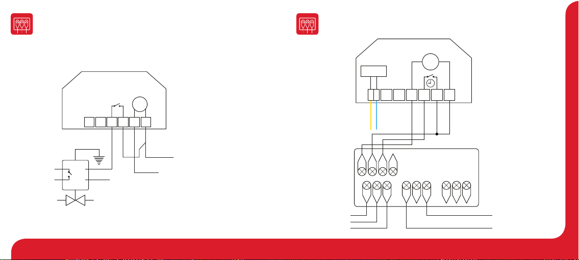
Wiring Diagram - 52UH873 to Valve
TO CONNECT BOILER CONSULT
BOILER MAKERS DIAGRAM
L
N
LS
LR
LS & LR ARE NORMALLY THE
ROOM THERMOSTAT CONNECTIONS
TO BOILER
HEATING VALVE
NEUTRAL
NEUTRAL
LIVE
230V SUPPLY IN
230V AC 50/60Hz
52UH873
A1A2 LN
230VAC
Wiring Diagram - 52UH873 to PRC Volt Free Switching
12V
COMMS
CABLE
A2 B2
NONCCNONCCNEL
230V SUPPLY IN Volt Free Output
POWERED RELAY CARD
+
_
Recommendations
Max Cable Size - 1.5MM
Back Box Depth - 35MM
Max Load - 3 Amps
For 230V switched live
output, link mains L to C
52UH873
RT2 RT1 -A2 A1 +
Y B
Network
12VDC
THIS UNIT MUST BE PROTECTED BY A FUSE OR RCD

3029 Slimline Series
Wiring Diagram - 52UH873 to 52UH108
COMMS
CABLE
52UH873
RT2 RT1 -A2 A1 +
Y B
Network
12VDC
52UH108
ZONE X
A2
A1
B
Y
_
+
ZONE X
A2
A1
B
Y
_
+
Connecting 52UH873 to the 52UH108
The 52UH108 allows connection of up to eight
12 volt network thermostats.
When connecting network thermostats
to the 52UH108 use CAT5-FTP or BELDEN 9538.
Connect the screen to Earth at the 52UH108.
Notes
.........................................................................................................................................................................
.........................................................................................................................................................................
.........................................................................................................................................................................
.........................................................................................................................................................................
.........................................................................................................................................................................
.........................................................................................................................................................................
.........................................................................................................................................................................
.........................................................................................................................................................................
.........................................................................................................................................................................
.........................................................................................................................................................................
.........................................................................................................................................................................
.........................................................................................................................................................................
.........................................................................................................................................................................
Table of contents
Popular Thermostat manuals by other brands


Supco
Supco CTC PROCOMM Series Installer manual

UTC Fire and Security
UTC Fire and Security Dialog quick start guide

Honeywell
Honeywell B/Q682 owner's manual

Danfoss
Danfoss RET B + RF User & installation instructions

Honeywell
Honeywell CTSOA installation instructions

Drayton
Drayton 13616 installation instructions