EG4 6500 EX-48 User manual

May 2022 | Rev A | Information subject to change without notice.
6.5KVA 120Vac
6500 EX-48
EG4 Electronics
www.eg4electronics.com

EG4 Inveer Set Up Guide:
To enter Menu - Press and ENTER for 3 seconds
•Program Setting 0
•Program Seing 2
r = BOA
•Program Seing 3
•Program Seing 4
•Program Seing 5
r =
EG4, for
all other batteries use User Defined Settings.
•Program Seing 6
•Program Seing 7
•Program Seing 9
•Program Seing 10
o
o
o
o
Program Seing 11
•Program Setting 1
Exit Setting Mode
EG4 Electronics
www.eg4electronics.com

•Program Seing 12
•Program Seing 13
•Program Seing 16
•Program Seing 18
•Program Seing 19
•Program Seing 20
•Program Se
tt
ing 22
Beep when primary source interrupted.
default is AON (enabled)
•Program Seing 23
•Program Seing 25
•Program Seing 26
r =
•Program Seing 27
r =
•Program Seing 28
•Program Seing 29
EG4 Electronics
www.eg4electronics.com

•Program Seing 30-3
6
o
Battery Equalization settings
When using EG4 you will not need these settings. If using flooded lead acid or AGM
batteries consult your batteries user manual for recommended Equalization settings.
•
Program Setting 37
o
Rest all stored data for PV generated power and output load energy
•
Program Setting 41
o
Maximum Discharging Current
Use this to set maximum battery discharging current
range is 30A to 150A
unit of change is in 10A increments
o
Note: For EG4 batteries maximum discharge is 100A
•
Program Setting 51
o
RGB LED ON/OFF Control
•
Program Setting 52
o
RGB Brightness Control
•
Program Setting 53
o
Effect Speed of RGB lighting
•
Program Setting 54
o
RGB Lighting Effects Menu
•
Program Setting 55
o
RGB Lighting Color Menu
•
Program Setting 93
o
Erase All Data Logged
•
Program Setting 94
o
Data Log Recorded Interval
Use this menu to determine the interval time (in minutes) that data is logged
•
Program Settings 95- 99
o
Data and Time Settings
EG4 Electronics
www.eg4electronics.com

Table of Contents
ABOUT THIS MANUAL ............................................................................................................................ 1
Purpose ......................................................................................................................................................... 1
Scope ............................................................................................................................................................ 1
SAFETY INSTRUCTIONS .........................................................................................................................1
INTRODUCTION .................................................................................................................................... 2
Features........................................................................................................................................................ 2
Basic System Architecture............................................................................................................................... 2
Product Overview ........................................................................................................................................... 3
INSTALLATION ....................................................................................................................................... 4
Unpacking and Inspection .............................................................................................................................. 4
Installation of Battery Wiring Extension Box and Cable Glands ..........................................................................4
Preparation ................................................................................................................................................... 5
Mounting the Unit .......................................................................................................................................... 5
Battery Connection ........................................................................................................................................ 6
AC Input/Output Connection ........................................................................................................................... 7
PV Connection ............................................................................................................................................... 8
Final Assembly ............................................................................................................................................... 10
Remote Display Panel Installation ................................................................................................................... 10
Communication Connection ............................................................................................................................ 12
Dry Contact Signal ......................................................................................................................................... 12
BMS Communication ...................................................................................................................................... 12
OPERATION ............................................................................................................................................ 13
Power ON/OFF............................................................................................................................................... 13
Inverter Turn-on............................................................................................................................................ 13
Operation and Display Panel ........................................................................................................................... 13
LCD Display Icons.......................................................................................................................................... 14
LCD Setting ................................................................................................................................................... 16
LCD Display ................................................................................................................................................... 30
Operating Mode Description ........................................................................................................................... 35
Faults Reference Code ................................................................................................................................... 38
Warning Indicator .......................................................................................................................................... 39
BATTERY EQUALIZATION ...................................................................................................................... 40
CLEARANCE AND MAINTENANCE FOR ANTI-DUST KIT......................................................................... 41
Overview....................................................................................................................................................... 41
Clearance and Maintenance ........................................................................................................................... 41
SPECIFICATIONS................................................................................................................................... 42
Table 1 Line Mode Specifications..................................................................................................................... 42
Table 2 Inverter Mode Specifications............................................................................................................... 43
Table 3 Charge Mode Specifications ................................................................................................................ 43
Table 4 General Specifications ........................................................................................................................ 45
TROUBLE SHOOTING ............................................................................................................................ 46
Appendix I: Parallel function ................................................................................................................ 47
Appendix II: BMS Communication Installation .................................................................................... 60
Appendix III: The Wi-Fi Operation Guide in Remote Panel ................................................................. 65
EG4 Electronics
www.eg4electronics.com
Appendix IIII: UL Listing ......................................................................................................................74

ABOUT THIS MANUAL
Purpose
This manual describes the assembly, installation, operation and troubleshooting of this unit. Please read
this manual carefully before installations and operations. Keep this manual for future reference.
Scope
This manual provides safety and installation guidelines as well as information on tools and wiring.
SAFETY INSTRUCTIONS
WARNING: This chapter contains important safety and operating instructions. Read and
keep this manual for future reference.
1. Before using the unit, read all instructions and cautionary markings on the unit, the batteries and all
appropriate sections of this manual.
2. CAUTION- Do not disassemble the unit. Take it to a qualified service center when service or repair
is required. Incorrect re-assembly may result in a risk of electric shock or fire.
3. To reduce risk of electric shock, disconnect all wirings before attempting any maintenance or cleaning.
Turning off the unit will not reduce this risk.
4. CAUTION – Only qualified personnel can install this device with a battery.
5. NEVER charge a frozen battery.
6. For optimum operation of this inverter/charger, please follow required spec to select appropriate cable
size. It’s very important to correctly operate this inverter/charger.
7. Be very cautious when working with metal tools on or around batteries. A potential risk exists to drop
a tool that can spark or short circuit batteries or other electrical parts and could cause an explosion.
8. Please strictly follow installation procedure when you want to disconnect AC or DC terminals. Please
refer to INSTALLATION section of this manual for details.
9. Fuses are provided as over-current protection for the battery supply.
10. GROUNDING INSTRUCTIONS -This inverter/charger should be connected to a permanent grounded
wiring system. Be sure to comply with local requirements and regulation to install this inverter.
11. NEVER short AC output and DC inputs. Do NOT connect to the grid with a shorted DC input.
12. Warning!! Only qualified service persons are able to service this device. If errors still persist after
following troubleshooting table, please contact your retailer for further assistance.
13. WARNING: Because this inverter is non-isolated, only three types of PV modules are acceptable:
Mono-crystalline, Polycrystalline with class A-rated, and CIGS modules. To avoid any malfunction, do
not connect any PV modules with possible current leakage to the inverter. For example, grounded PV
modules will cause current leakage to the inverter. When using CIGS modules, please be sure NOT to
ground.
14. CAUTION: It is recommended to use DC breakers for surge protection on PV lines. Otherwise, it will
cause damage to the inverter if lightning strike occurs on PV modules.
EG4 Electronics
www.eg4electronics.com
1

INTRODUCTION
This is a residential self consumption multi-function inverter, combining the functions of an inverter, solar
charger and battery charger to offer uninterrupted power support in a single package. The comprehensive
LCD display offers user-configurable and easy-accessible button operations such as battery charging
current, AC or solar charging priority, and acceptable input voltage based on different applications.
Features
Pure sine wave inverter >3% THD
Configurable color with the built-in RGB LED bar
Built-in Wi-Fi for mobile monitoring (APP is required)
Supports USB On-the-Go function to easily upgrade firmware
Built-in anti-dust kit
Detachable LCD control module with multiple communication ports for BMS (RS485, CAN-BUS,
RS232)
Configurable input voltage tolerances for home appliances and personal computers via LCD control panel
Configurable AC/PV output usage timer and prioritization
Configurable AC/Solar charger priority via LCD control panel
Configurable battery charging current based on applications via LCD control panel
Compatible with the grid or generator power
Auto restart on AC reconnect
Overload / Over temperature / short circuit protection
Smart battery charger design for optimized battery performance
Basic System Architecture
The following illustration shows basic application for this unit - including the below-listed devices needed for
a complete running system:
Generator or Utility
48V Battery
PV modules
Consult with your system integrator for other possible system architectures depending on your
requirements.
This inverter can power various 120v appliances in home or office environment, including motor-type
appliances such as tube light, fan, refrigerator and air conditioners.
Figure 1 Basic PV System Overview
EG4 Electronics
www.eg4electronics.com
2
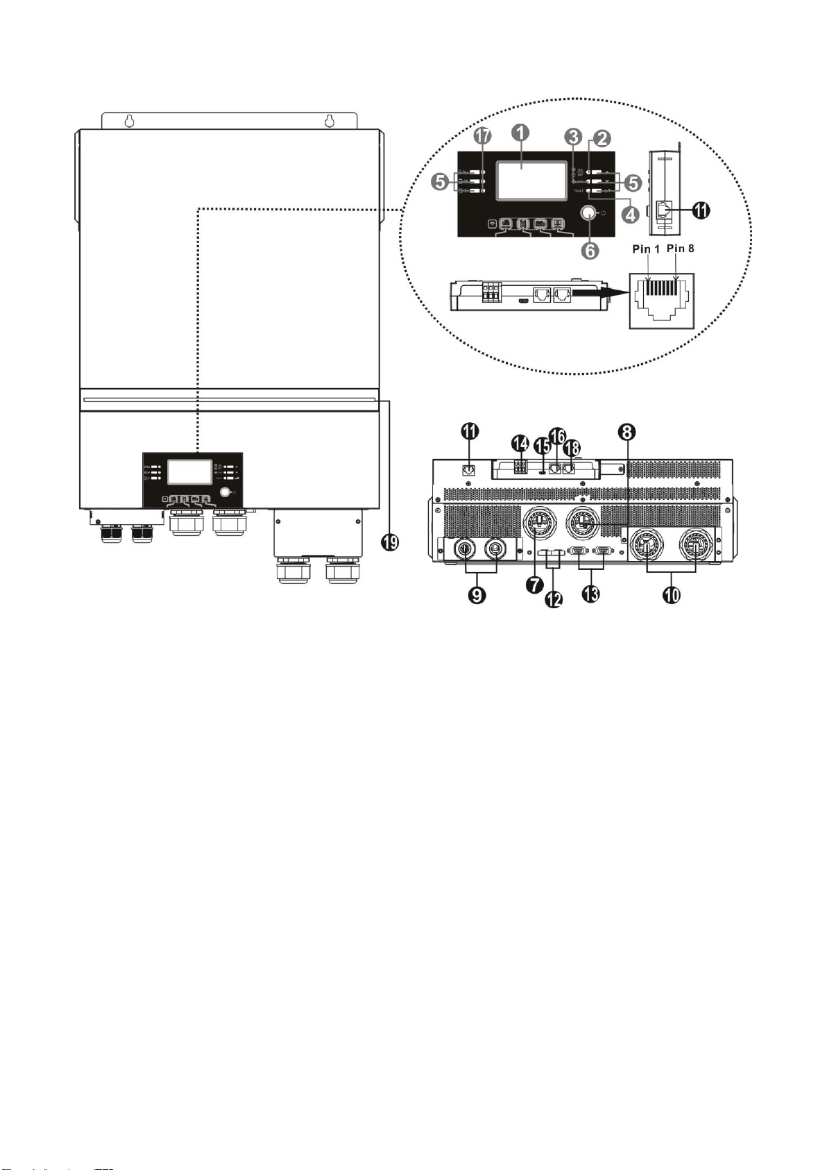
Product Overview
NOTE: 6.5KW is a parallel model. For parallel installation and operation, please check
Appendix I.
1. LCD display
2. Status indicator
3. Charging indicator
4. Fault indicator
5. Function buttons
6. Power on/off switch
7. AC input connectors
8. AC output connectors (Load connection)
9. PV terminal
10. Battery connectors
11. Remote LCD module communication
12. Current sharing port
13. Parallel communication port
14. Dry contact
15. OTG-USB port as USB communication port and USB
function port
16. BMS communication port: CAN, RS-485 or RS-232
17. Output source indicators (refer to OPERATION/Operation
and Display Panel section for details) and USB function
setting reminder (refer to OPERATION/Function Setting for
the details)
18. RS-232 communication port for firmware updates from a
PC
19. RGB LED bar (refer to LCD Setting section for the details)
Port
NOTE: For parallel model installation and operation, please check the parallel installation guide (pg. 47) for details.
EG4 Electronics
www.eg4electronics.com
3
INSTALLATION:
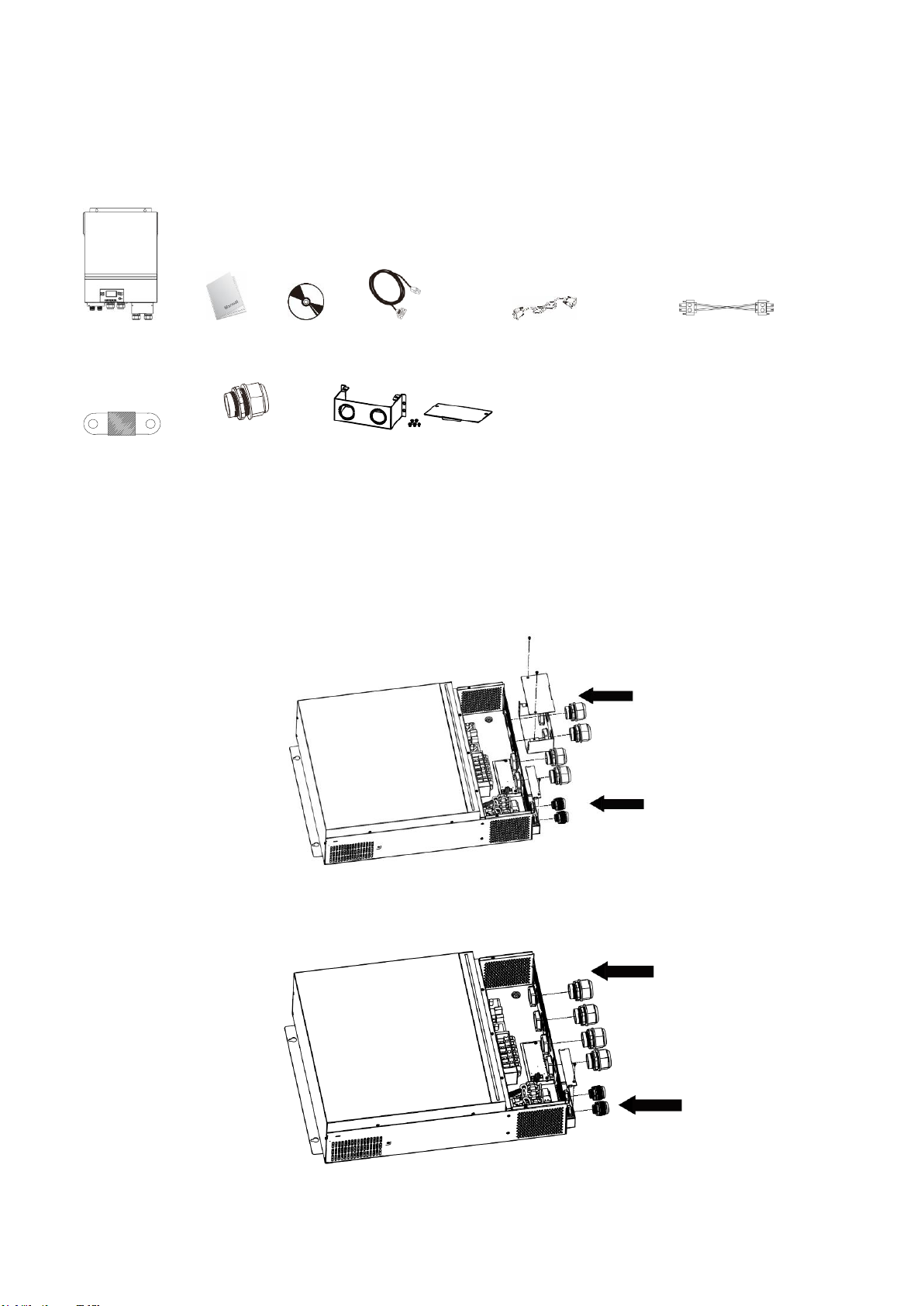
Unpacking and Inspection
Before installation, please inspect the unit. Be sure that nothing inside the package is damaged. You
should have received the following items:
Inverter unit Manual software CD RS-232 cable Parallel communication cable Current sharing cable
DC Fuse Cable gland x 4 pcs Extension Box Kit
Installation of Battery Wiring Extension Box,Cable Glands, and
Conduit Fittings 1/2" or 3/4"
Install two (2) cable glands or conduit fittings on the extension box, then fix the extension box on the
rear panel of the inverter.
Note: Installation of the battery wiring extension box is necessary for UL
conformity. If UL conformity is not required in your region, it is sufficient to only install the cable glands
(Graphic 2) shown below.
Fig.1 6500 with Extension Box
Fig.2 6500 without Extension Box
EG4 Electronics
www.eg4electronics.com
4
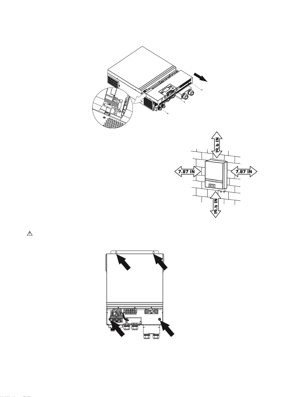
Preparation
Before connecting all wirings, please take off bottom cover by removing five screws. When removing the
bottom cover, be carefully to remove three cables as shown below.
Mounting the Unit
Consider the following points before selecting where to install:
⚫Do not mount the inverter on flammable construction materials.
⚫Mount on a solid surface
⚫Install this inverter at eye level in order to allow the LCD display to
be read at all times.
⚫The ambient temperature should be between 0°C and 55°C to
ensure optimal operation.
⚫The recommended installation position is to be adhered to the wall
vertically.
⚫Be sure to keep other objects and surfaces as shown in the right
diagram to guarantee sufficient heat dissipation and to have
enough space for removing wires.
⚫3ft of space or more on the bottom for servicing unit.
SUITABLE FOR MOUNTING ON CONCRETE OR OTHER NON-COMBUSTIBLE SURFACE ONLY.
Install the unit by screwing four screws. It’s recommended to use M4 or M5 screws.
EG4 Electronics
www.eg4electronics.com
5

Battery Connection
CAUTION: For safety operation and regulation compliance, it is recommended that a separate DC over-
current protector or disconnect device be installed between the battery and inverter. It may not be
required to have a disconnect device in some applications, however, it is still recommended to have
over-current protection installed. Please refer to the typical amperage in table below for required fuse or
breaker size.
WARNING! All wiring must be performed by qualified personnel.
WARNING! It is very important for system safety and efficient operation
to use the appropriate cable size for battery connection. To reduce risk of
injury, please use the recommended cable and terminal size in the table
below.
Recommended battery cable and terminal size:
Model
Typical
Amperage
Battery
capacity
Wire Size
Cable
mm2
Ring Terminal
Torque
value
Dimensions
D (mm)
L (mm)
6.5KW
153A
250AH
1*2/0AWG
67
8.4
47
5 Nm
Please follow the below steps to implement battery connection:
1. Assemble battery ring terminal based on recommended battery cable and terminal size.
2. Fix two cable glands into positive and negative terminals.
3. Insert the ring terminal of battery cable flatly into battery connector of inverter and make sure the nuts are
tightened with torque of 5 Nm (3.6ft lbs). Make sure polarity at both the battery and the inverter/charge
is correctly connected and ring terminals are tightly screwed to the battery terminals.
WARNING: Shock Hazard
Installation must be performed with care due to high battery voltage in series.
CAUTION!! Do not place anything between the flat part of the inverter terminal and the ring
terminal. Otherwise, overheating may occur.
CAUTION!! Do not apply anti-oxidant substance on the terminals before terminals are connected
tightly.
CAUTION!! Before making the final DC connection or closing DC breaker/disconnector, be
sure positive (+) is connected to positive (+) and negative (-) is connected to negative (-).
Ring terminal:
EG4 Electronics
www.eg4electronics.com
6
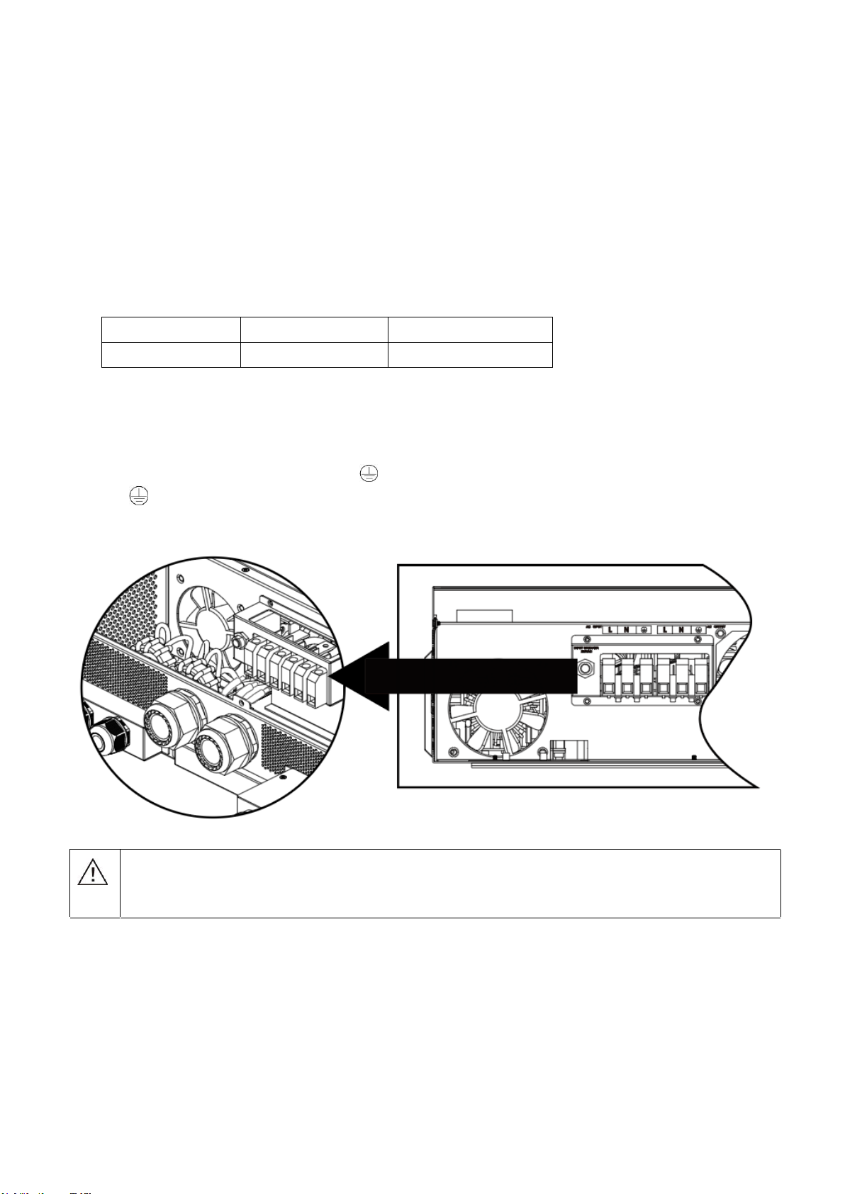
AC Input/Output Connection
CAUTION!! Before connecting to AC input power source, please install a separate AC breaker between
the inverter and AC input power source. This will ensure the inverter can be securely disconnected
during maintenance and fully protected from over current of AC input.
CAUTION!! There are two terminal blocks with “IN” and “OUT” markings. Please do NOT mis-connect input
and output connectors.
WARNING! All wiring must be performed by a qualified personnel.
WARNING! It is very important for system safety and efficient operation to use appropriate cable for AC
input connection. To reduce risk of injury, please use the proper recommended cable size below.
Suggested cable requirement for AC wires
Model Gauge Torque Value
6.5KW 4 AWG 1.4~ 1.6Nm
Please follow below steps to implement AC input/output connection:
1. Before making AC input/output connection, be sure to open DC protector or disconnector first.
2. Remove insulation sleeve 10mm for six conductors. And shorten phase L and neutral conductor N 3 mm.
3. Fix two cable glands into input and output sides.
4. Insert AC input wires according to polarities indicated on terminal block and tighten the terminal screws. Be
sure to connect PE protective conductor ( ) first.
→Ground (yellow-green)
L→LINE (brown or black)
N→Neutral (blue)
WARNING:
Be sure that the AC power source is disconnected before attempting to hardwire it to the
unit.
EG4 Electronics
www.eg4electronics.com
7

5. Then, insert AC output wires according to polarities indicated on terminal block and tighten terminal screws.
Be sure to connect PE protective conductor ( ) first.
→Ground (yellow-green)
L→LINE (brown or black)
N→Neutral (blue)
6. Make sure the wires are securely connected.
PV Connection
CAUTION: Before connecting to PV modules, please install separate DC circuit breakers between inverter
and PV modules.
NOTE: Please use 600VDC/30A circuit breaker. The over voltage category
of the PV input is
II.
Please follow
the steps
below to
implement PV module connection
Step 1: Check the input voltage of PV array modules. This system is applied with two strings of PV array. Please
make sure that the maximum current load of each PV input connector is 18A.
Step 2: Disconnect the circuit breaker and switch off the DC switch.
CAUTION: Appliances such as air conditioners require at least 2~3 minutes to restart because it’s
necessary to have enough time to balance refrigerant gasses inside of circuits. If a power outage
occurs and recovers in a short time, it may cause damage to your connected appliance. To prevent
damage, please check with the manufacturer of the air conditioner to see if it is equipped with a time -
delay function before installation. This inverter/charger may trigger an overload fault and shut off
the AC output to protect your appliance which may cause internal damage to the air conditioner.
CAUTION: Important
Be sure to connect AC wires with correct polarity. If L and N wires are reversed, it may cause a
short-circuit when these inverters are in parallel operation.
CAUTION: Exceeding the maximum input voltage can destroy the unit!! Check the system before wire connection.
WARNING: Because this inverter is non-isolated, only three types of PV modules are acceptable:
monocrystalline and polycrystalline with class A-rated and CIGS modules.
To avoid any malfunction, do not connect any PV modules with possible current leakage to the inverter. For
example, grounded PV modules will cause current leakage to the inverter. When using CIGS modules,
please be sure NOT to ground.
CAUTION: It is required to use PV junction box with surge protection. Otherwise, it will cause damage
to the inverter when lightning occurs on PV modules.
EG4 Electronics
www.eg4electronics.com
8
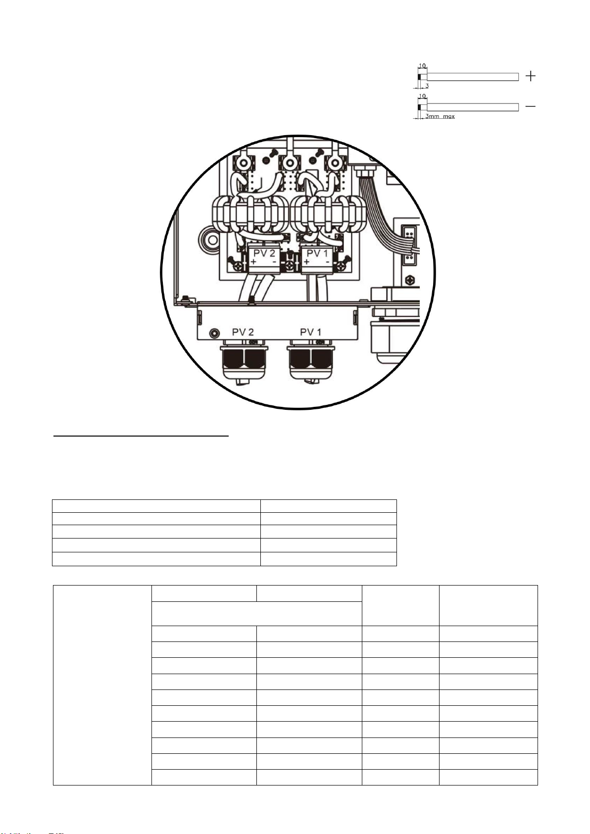
Step 3: Assemble PV terminals with PV modules by the following steps.
Please follow below steps to implement PV module connection:
1. Remove insulation sleeve 10 mm for positive and negative conductors.
2. Check correct polarity of connection cable from PV modules and PV input
connectors. Then, connect positive pole (+) of connection cable to positive
pole (+) of PV input connector. Connect negative pole (-) of connection cable
to negative pole (-) of PV input connector.
3. Make sure the wires are securely connected.
Recommended Panel Configuration
When selecting proper PV modules, please be sure to consider the following parameters:
1. Open circuit Voltage (Voc) of PV modules not to exceed maximum PV array open circuit voltage of the
inverter.
2. Open circuit Voltage (Voc) of PV modules should be higher than the start-up voltage.
INVERTER MODEL 6.5KW
Max. PV Array Power 8000W
Max. PV Array Open Circuit Voltage 500Vdc
PV Array MPPT Voltage Range 90Vdc~450Vdc
Start-up Voltage (Voc) 80Vdc
Example solar panel configuration for 6.5KW model:
Solar Panel Spec.
(reference)
-330Wp
- Vmp: 33.7Vdc
- Imp: 9.79A
- Voc: 39.61Vdc
- Isc: 10.4A
- Cells: 60
SOLAR INPUT 1
SOLAR INPUT 2
Q'ty of panels
Total Input Power
Min in series: 3pcs, per input
Max. in series:12pcs, per input
3pcs in series
x
3pcs
990W
x
3pcs in series
3pcs
990W
6pcs in series
x
6pcs
1980W
x
6pcs in series
6pcs
1980W
12pcs in series
x
12pcs
3960W
x
12pcs in series
12pcs
3960W
6pcs in series
6pcs in series
12pcs
3960W
6pcs in series, 2 strings
x
12pcs
3960W
x
6pcs in series, 2 strings
12pcs
3960W
6pcs in series, 2 strings
6pcs in series, 2 strings
24pcs
7920W
EG4 Electronics
www.eg4electronics.com
9
Final Assembly
After correctly connecting all wiring, re-connect three cables and then put bottom cover back by screwing
five screws as shown below.
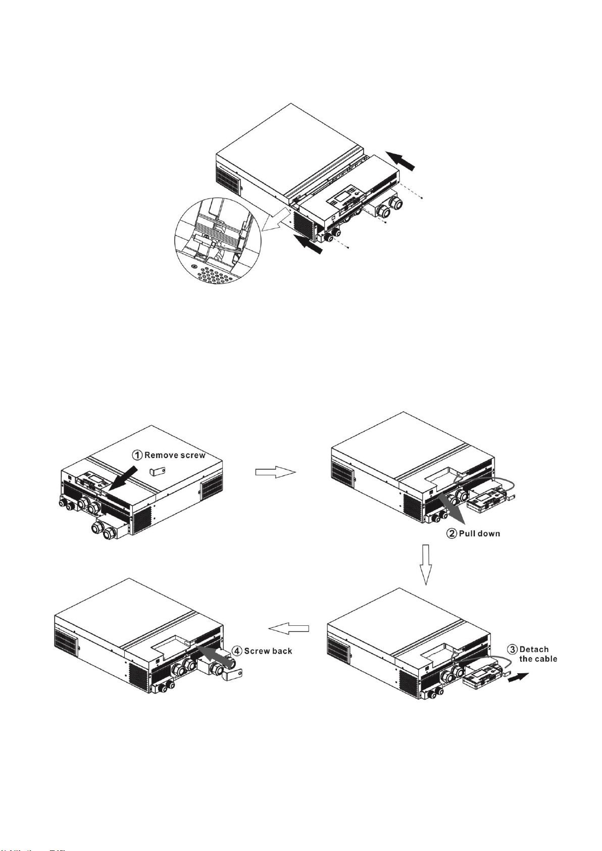
Remote Display Panel Installation
The LCD module can be removed and installed in a remote location with an optional communication cable.
Please take the follow steps to implement this remote panel installation.
Step 1. Remove the screw on the bottom of LCD module and pull down the module from the case.Detach the
cable from the original communication port. Be sure to replace the retention plate back to the inverter.
EG4 Electronics
www.eg4electronics.com
10

Step 2. Prepare your mounting holes in the marked locations as shown in the illustration below. The LCD
module then can be securely mounted to your desired location.
Note: Wall installation should be implemented with the proper screws to the right.
Step 3. After LCD module is installed, connect LCD module to the inverter with an optional RJ45
communication cable as shown below.
M3
Ø5-Ø9
RS-232 communication
to PC
USB communication to
PC
BMS communication
Remote communication
EG4 Electronics
www.eg4electronics.com
11

Communication Connection
Serial Connection
Please use the supplied serial cable for connection between the inverter and your PC. Install the
monitoring software from the bundled CD and follow the on-screen instructions to complete your installation.
For detailed software operation, refer to the software user manual on the bundled CD.
Wi-Fi Connection
This unit is equipped with a Wi-Fi transmitter. The Wi-Fi transmitter can enable wireless communication
between off-grid inverters and monitoring platform. Users can access and control the monitored
inverter with downloaded APP. You can find the “WatchPower” app on the Apple® Store or “WatchPower
Wi-Fi” in the Google® Play Store. All data loggers and parameters are saved in iCloud. For quick installation
and operation, please check Appendix III.
Dry Contact Signal
There is one dry contact (3A/250VAC) available on the rear panel. It could be used to deliver signal to external
device when battery voltage reaches warning level.
Unit Status
Condition
Dry contact port:
NC & C
NO & C
Power Off
Unit is off and no output is powered.
Close
Open
Power On
Output is
powered
from Battery
power or
Solar energy.
Program 01
set as USB
(utility first)
or SUB (solar
first)
Battery voltage < Low DC
warning voltage
Open
Close
Battery voltage > Setting
value in Program 13 or
battery charging reaches
floating stage
Close
Open
Program 01 is
set as SBU
(SBU priority)
Battery voltage < Setting
value in Program 12
Open
Close
Battery voltage > Setting
value in Program 13 or
battery charging reaches
floating stage
Close
Open
BMS Communication
A special communication cable is required if you are connecting to Lithium-Ion battery banks. Please refer
to
Appendix II- BMS Communication Installation
for details.
EG4 Electronics
www.eg4electronics.com
12
OPERATION
Power ON/OFF
Once the unit has been properly installed and the batteries are connected correctly, simply press the On/
Off switch (located on the display panel) to turn on the unit.
Inverter Start-Up
After this inverter is turned on, the WELCOME light show will be started with RGB LED BAR. It will slowly
cycle through entire spectrum of nine colors (Green, Sky blue, Royal blue, Violet, Pink, Red, Honey, Yellow,
Lime yellow) for about 10-15 seconds. After initialization, it will light up with default color.
The RGB LED bar can light up in different color and light effects based on the setting of energy priority to
display the operation mode, energy source, battery capacity and load level. Parameters such as color, effects,
brightness, speed and so on can be configured through the LCD panel. Please refer to LCD settings for the
details.
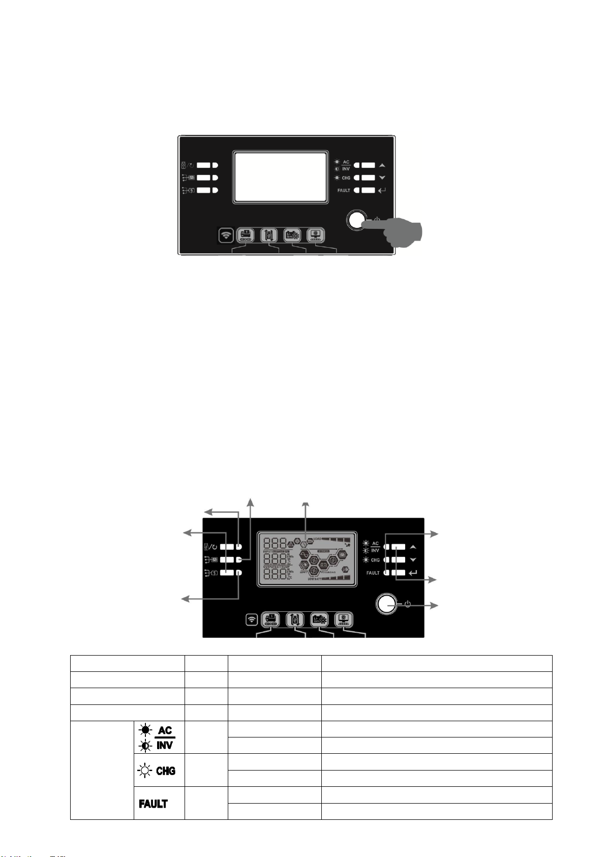
Operation and Display Panel
The operation and the LCD module, shown in the chart below, includes six indicators, six function keys, on/off
switch and a LCD display to indicate the operating status and input/output power information.
Indicators
LED Indicator
Color
Solid/Flashing
Messages
Setting LED 1
Green
Solid On
Output powered by utility
Setting LED 2
Green
Solid On
Output powered by PV
Setting LED 3
Green
Solid On
Output powered by battery
Status
indicators
Green
Solid On
Output is available in line mode
Flashing
Output is powered by battery in battery mode
Green
Solid On
Battery is fully charged
Flashing
Battery is charging.
Red
Solid On
Fault mode
Flashing
Warning mode
Status indicators
Function keys
On/off switch
Function keys
Setting LED 3
Setting LED 1
Setting LED 2
LCD display
EG4 Electronics
www.eg4electronics.com
13
Function Keys
Function Key
Description
ESC
Exit the setting
USB function setting
Select USB OTG functions
Timer setting for the Output source
priority
Setup the timer for prioritizing the output source
Timer setting for the Charger source
priority
Setup the timer for prioritizing the charger source
+
Press these two keys at the same time to switch RGB
LED bar between output source priority and battery
discharge/charge status.
Up To last selection
Down To next selection
Enter To confirm/enter the selection in setting mode
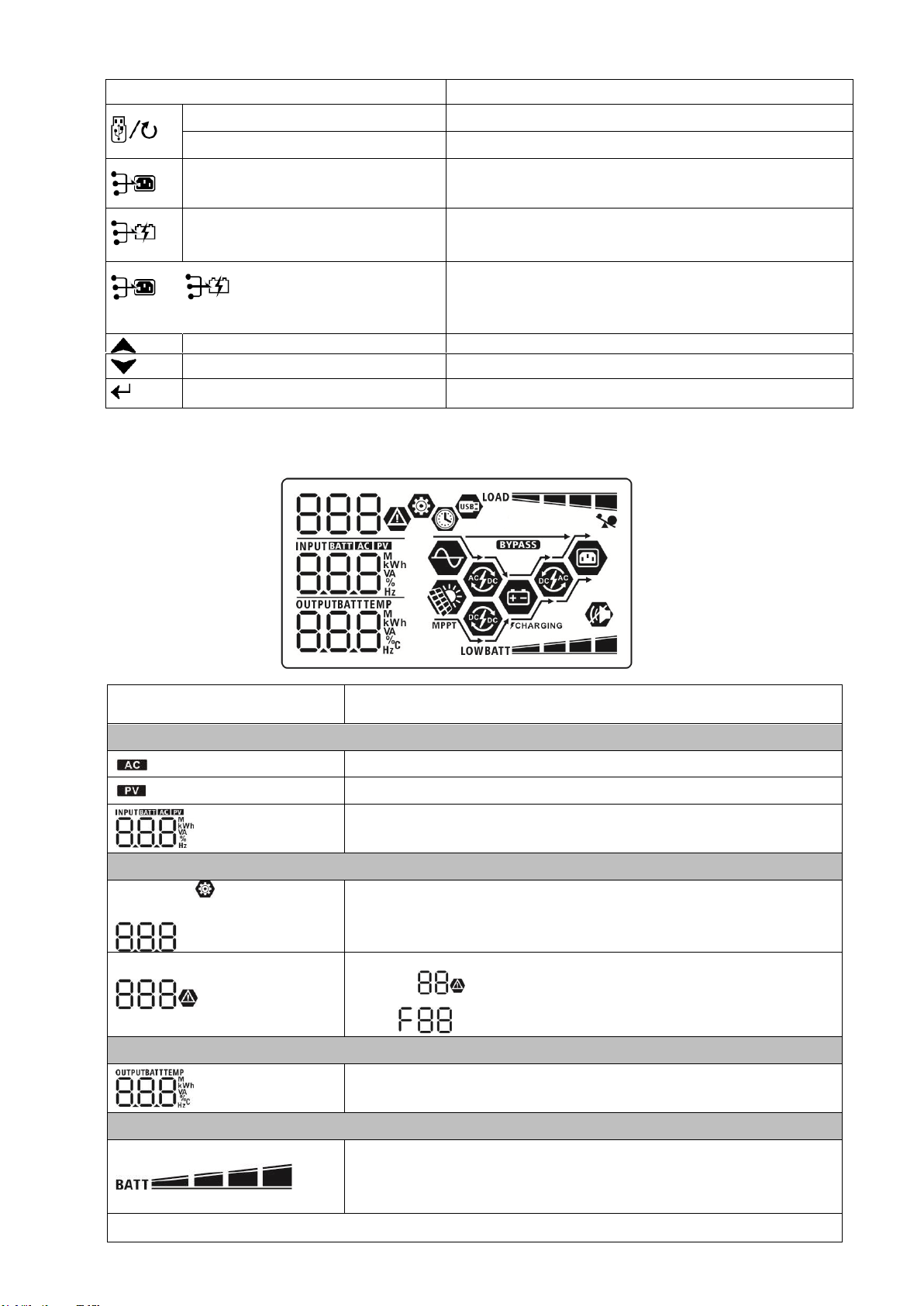
LCD Display Icons
Icon
Function description
Input Source Information
Indicates the AC input.
Indicates the PV input
Indicates input voltage, input frequency, PV voltage, charger
current, charger power, battery voltage.
Configuration Program and Fault Information
Indicates the setting programs.
Indicates the warning and fault codes.
flashing with warning code.
Fault: lighting with fault code
Output Information
Indicates output voltage, output frequency, load percent, load in
VA, load in Watt and discharging current.
Battery Information
Indicates battery level by 0-24%, 25-49%, 50-74% and 75-100% in
battery mode and charging status in line mode.
NOTE: When battery is
charging, it will
present battery charging
status.
Warning:
EG4 Electronics
www.eg4electronics.com
14

Status Battery voltage LCD Display
Constant
Current mode /
Constant
Voltage mode
<2V/cell 4 bars will flash in turns.
2 ~ 2.083V/cell Bottom bar will be on and the other three bars
will flash in turns.
2.083 ~ 2.167V/cell Bottom two bars will be on and the other two
bars will flash in turns.
> 2.167 V/cell Bottom three bars will be on and the top bar will
flash.
Floating mode. Batteries are fully charged. 4 bars will be on.
In battery mode, it will present battery capacity.
Load Percentage Battery Voltage LCD Display
Load >50%
< 1.85V/cell
1.85V/cell ~ 1.933V/cell
1.933V/cell ~ 2.017V/cell
> 2.017V/cell
Load < 50%
< 1.892V/cell
1.892V/cell ~ 1.975V/cell
1.975V/cell ~ 2.058V/cell
> 2.058V/cell
Load Information
Indicates overload.
Indicates the load level by 0-24%, 25-49%, 50-74% and 75-100%.
0%~24% 25%~49%
50%~74% 75%~100%
Mode Operation Information
Indicates unit connects to the mains.
Indicates unit connects to the PV panel.
Indicates load is supplied by utility power.
Indicates the utility charger circuit is working.
Indicates the solar charger circuit is working.
Indicates the DC/AC inverter circuit is working.
Indicates unit alarm is disabled.
Indicates USB disk is connected.
Indicates timer setting or time display
EG4 Electronics
www.eg4electronics.com
15
Other manuals for 6500 EX-48
1
Table of contents
Other EG4 Inverter manuals


Popular Inverter manuals by other brands

RNG
RNG KIT-STCS60D owner's manual

Mitsubishi Electric
Mitsubishi Electric FR-D720-0.4K instruction manual

FoxESS
FoxESS T Series user manual

UNIRAC
UNIRAC SolarMount installation manual

meibes
meibes Solarstation XXL Technical information for installation and operation

EnerSys
EnerSys OutBack Power Radian International Series Operator's manual


EASTMAN
EASTMAN ESM3K/48 manual

Wagan
Wagan Slim Line user manual

Vector
Vector MAXX SST VEC056D User's manual & warranty information

Toshiba
Toshiba TOSVERT VF-S9 instruction manual

ULTIMATE SPEED
ULTIMATE SPEED 300W USSW 300 B2 Operation and safety notes translation of the original instructions

Sealey
Sealey GG0720 instructions