HERBORNER pumpentechnik UNIBAD-X User manual
A - UX40 GB
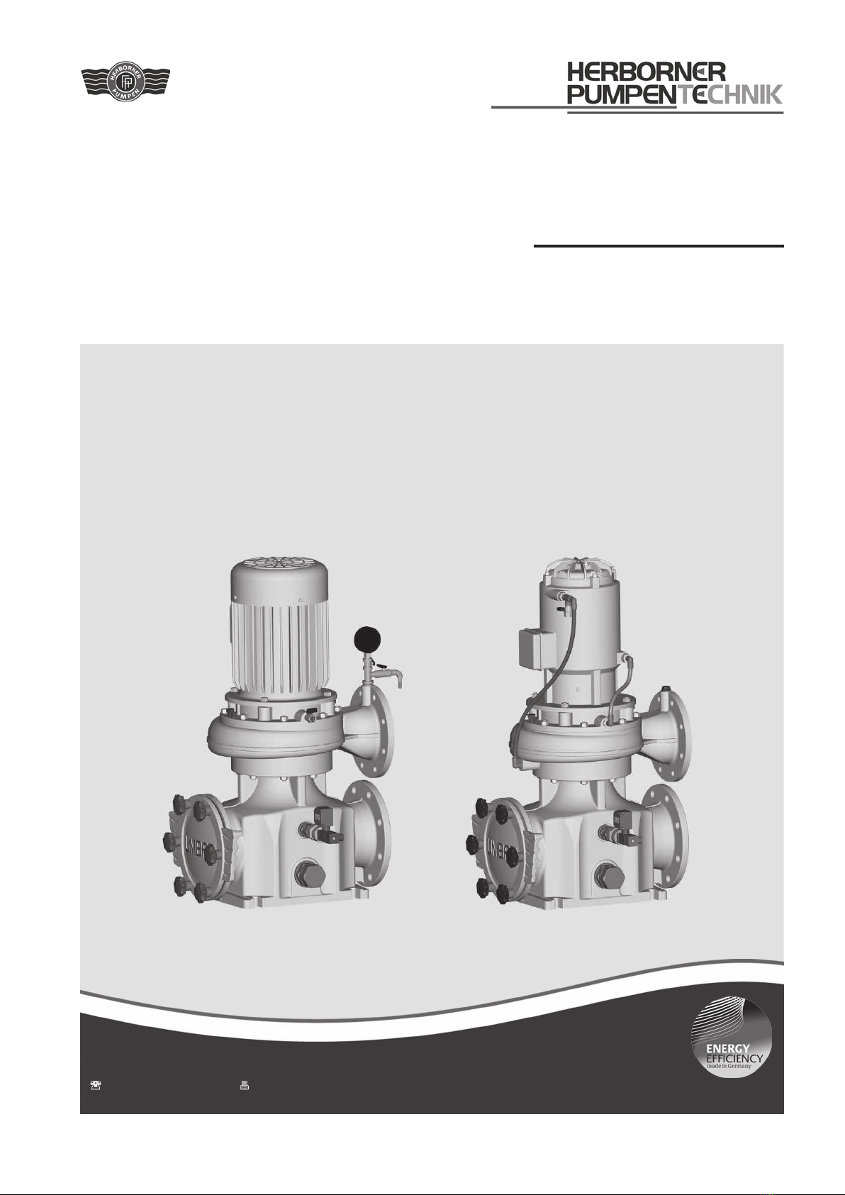
UNIBAD
Bath water circulating pump
Operating manual Model - X
- XC
- X-PM
J.H. Hoffmann GmbH & Co. KG | Littau 3-5 | DE-35745 Herborn
+49 (0) 27 72 / 933-0 | +49 (0) 27 72 / 933-100

Copyright
The transfer and duplication of this document and utilisation
and communication of its content is prohibited, unless ex-
plicitly stated otherwise. Non-compliance with this stipulation
will result in compensation for damages.
All rights reserved.
Translation
Deliveries to countries of the EEA require the operating
manual to be translated in accordance with the language
spoken in the respective country.
If any discrepancies should occur in the translated text,
reference should be made to the original operating manual
(German) for clarification or the manufacturer is to be con-
tacted.

Herborn, 29-12-2009 ....................................................................
Signature
(Management)
EC Declaration of Conformity
Herborner Pumpenfabrik
J.H. Hoffmann GmbH & Co. KG
Littau 3-5, 35745 Herborn, Germany
Ms J. Weygand is authorised to create the technical documentation.
Herborner Pumpenfabrik
J.H. Hoffmann GmbH & Co. KG
J. Weygand
Littau 3-5, 35745 Herborn, Germany
We hereby declare that the
Bath water circulating pump
UNIBAD/ -XC/ -PM
complies with all pertinent provisions of the EC Machinery Directive 2006/42/EC.
The machine also complies with all pertinent provisions of the following EC directives:
- Directive 2004/108/EC, Appendices I and II
J.H. Hoffmann GmbH & Co. KG | Littau 3-5 | DE-35745 Herborn
+49 (0) 27 72 / 933-0 | +49 (0) 27 72 / 933-100


Table of contents
5
Table of contents
1 General information.................................... 6
1.1 Intended use ................................................. 6
1.2 Exploded view............................................... 7
1.3 Wear parts..................................................... 8
1.4 Technical specifications................................. 8
1.4.1 Model designation......................................... 8
1.4.2 Impellers........................................................ 9
1.4.3 Installation..................................................... 9
1.4.4 Shaft sealing ................................................. 9
1.4.5 Drive.............................................................. 9
1.4.6 Dimensions, weight, performance data....... 10
1.4.7 General data ............................................... 10
2 Safety ......................................................... 12
2.1 Notes / explanations.................................... 12
2.1.1 Machine identification.................................. 12
2.2 Integrated safety systems (optional) ........... 13
2.3 Connections on the pump ........................... 13
2.4 Safety measures ......................................... 14
2.5 Obligations of the operator.......................... 14
3 General hazard warnings ......................... 15
3.1 Dangers....................................................... 15
3.2 Danger zones on the pump......................... 15
3.3 Assembly, operation and maintenance
personnel .................................................... 15
3.4 Installation of replacement parts and wear
parts ............................................................ 15
3.5 Shut off procedures..................................... 16
4 Transport.................................................... 17
4.1 Scope of delivery......................................... 17
4.2 Transport and packaging ............................ 17
4.2.1 Delivery (including spare parts and re-
placement parts) ........................................... 17
4.2.2 Intermediate storage ................................... 17
4.3 Transport to the site of installation (by the
customer) .................................................... 17
4.3.1 Transport with a forklift truck ....................... 17
4.3.2 Transport with a crane ................................ 18
5 Installation / fitting .................................... 19
5.1 Installation................................................... 19
5.2 Dimensions ................................................. 20
5.2.1 Dimensions of X/X-PM model ..................... 20
5.2.2 Dimensions of XC model............................. 23
5.3 Technical specifications............................... 25
5.4 Electrical connection ................................... 26
5.5 Motor protection .......................................... 26
5.6 Direction of rotation check........................... 26
5.6.1 Change of direction of rotation.................... 27
5.7 Motor connection diagrams......................... 27
5.7.1 PTC thermistor connection.......................... 28
5.8 Frequency converter operation ................... 28
5.9 ETS X4........................................................ 28
5.10 Laying the pipes.......................................... 28
5.11 Soiling monitor of the filter strainer.............. 29
5.12 Frost protection ........................................... 29
6 Commissioning ......................................... 30
6.1 Mounting the screw connection................... 31
6.2 Adjusting the soiling monitor ....................... 31
6.3 Operating modes and connecting frequen-
cy................................................................. 31
6.4 Starting up................................................... 32
7 Maintenance / cleaning............................. 33
7.1 Maintenance................................................ 33
7.2 Maintenance instructions for prolonged
periods of inactivity...................................... 34
7.3 Bearing lubrication ...................................... 34
7.3.1 Relubrication unit ........................................ 34
7.3.2 Greasing intervals ....................................... 35
7.4 Seals ........................................................... 35
7.5 Cleaning...................................................... 36
7.6 Cleaning the filter strainer ........................... 36
7.7 Tightening torques for nuts and bolts.......... 37
7.8 Disposal ...................................................... 37
8 Disturbance / cause / trouble shooting... 38
9 Disassembly / assembly........................... 40
9.1 Disassembly................................................ 40
9.2 Assembly..................................................... 42
Table of figures
Figure 1a Exploded view (X/X-PM model) .................... 7
Figure 1b Exploded view (XC model)............................ 7
Figure 2 Name plate.................................................. 13
Figure 3 Connections on the pump ........................... 13
Figure 4 Transport with a crane ................................ 18
Figure 5a Dimensions (X/X-PM model)....................... 20
Figure 5b Dimensions (XC model) .............................. 23
Figure 6 Venting label................................................ 30
Figure 7 Screw connection label ............................... 31
Figure 8 Assembly of screw connection.................... 31
Figure 9 Screw connection with sealing cover .......... 31
Figure 10 Screw connection for pipeline ..................... 31
Figure 11 Dry running label......................................... 34
Figure 12 Relubrication label....................................... 35
Figure 13 Cleaning of filter strainer with sealing lip..... 36
Figure 14 Star handle label ......................................... 37
General information
6
Danger!
Pumping flammable or explosive liq-
uids is perilous.
Do not pump flammable or explosive
liquids.
Caution!
Pumping any liquid which chemically
attacks the pump material or contains
abrasive ingredients can destroy the
pump.
Use bronze or stainless steel as the
pump material for these media.
The media used for the intended operation of the pump
and the associated dangers are the responsibility of the
operator.
Important!
Intended use also extends to observing the operating and
maintenance conditions prescribed by the manufacturer.
1 General information
1.1 Intended use
The swimming pool water circulation pump UNIBAD with inte-
grated hair and fibre filter for dirt separation is the centrepiece
of modern circulation systems for the delivery and filtering of
swimming pool water, fresh water, brine, sea water, service
water, and other liquids contaminated by coarse materials.
It is used in indoor, outdoor, and adventure swimming baths,
water parks, and ice sports, recreation, and hotel facilities for
water slides, attractions, water treatment systems, fountains,
heat recovery systems, and industrial facilities.
Model UNIBAD
Bath water circulating pump
Model UNIBAD-XC
Energy-saving bath water circulating pump with water-
cooled motor (the loss heat of the motor is used to heat the
medium)
Type UNIBAD-PM
Energy-saving bathwater circulation pump in version with
PM motor (permanent-magnet motor) with extremely high
efficiencies
Each pump is solely intended for the purpose previously
specified. Any other application or applications extending
beyond the stated purpose or alterations made to the pump
without prior written agreement with the manufacturer is
not permitted. The manufacturer is not liable for damages
resulting from unintended use. The responsibility is solely
that of the user.
Notice!
Lack of safety equipment can damage the pump.
The pumping station must conform to the respective direc-
tives and all safety equipment must be installed and fully
operational.
Only then should the pump be operated.
General information
7
006
940
704
433
171
1.)
502
2.)
920
400.1
101
702
001
005.2
320.2
423
819
113
230
554
412.2
903
400.2
002
003
004
802
320.1
005.1
412.1
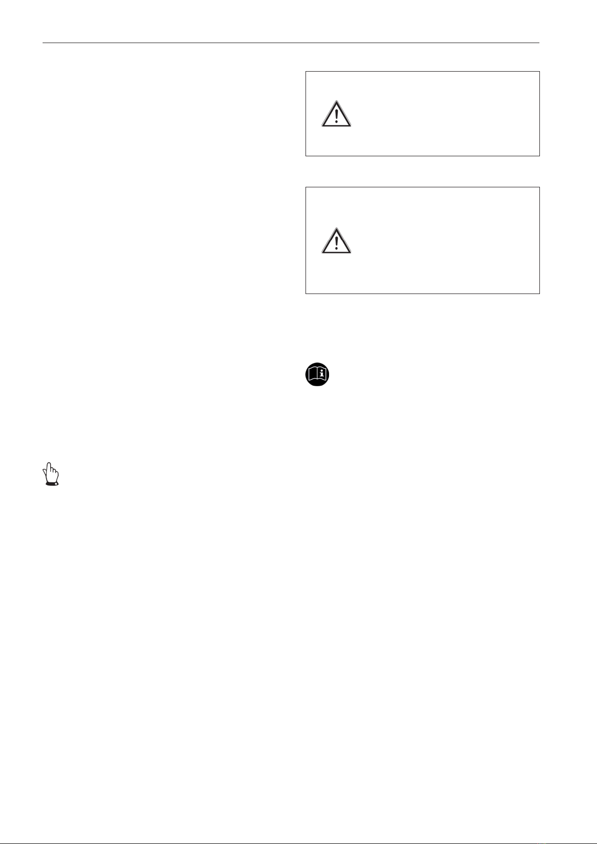
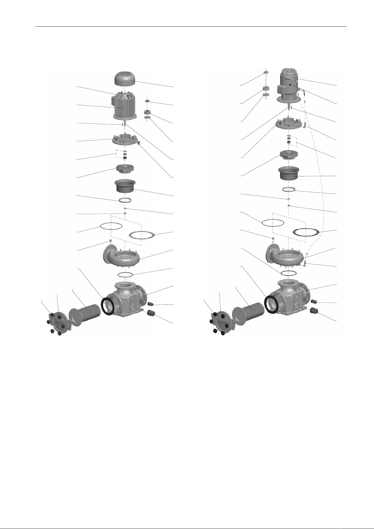
1.2 Exploded view
Model X/X-PM
Figure 1a Exploded view (X/X-PM model)
Model XC
Figure 1b Exploded view (XC model)
1.)
Only exists in case of design with screw propeller.
2.)
Only exists in case of design with closed multi vane impeller in material design W3, but not for 200-250/... and 200-270/....
320.
1
320.
2
423
819
006
171 1.
)
554
400.
1
101
412.
1
001
005.
2
802
940
113
433
230
502 2.)
920
412.2
903
002
003
004
832
831
005.
1
400.2
General information
8
Individual components
001 Filter casing
002 Filter strainer
003 Filter cover
004 Star handle
005.1 Screwed connection
005.2 Screwed connection
006 Ball valve
101 Pump casing
113 Intermediate casing
171
1)
Guiding ring
230 Impeller
320.1 Anti-friction bearing (non drive side)
320.2 Anti-friction bearing (drive side)
400.1 Gasket
400.2
3)
Gasket
412.1 O-ring
412.2 O-ring
423 Labyrinth ring
433 Mechanical seal
502
2)
Casing wear ring
554 Washer
702 Return pipe
704 Cooling water pipe
802 Block motor
819 Motor shaft
831 Fan
832 Fan hood
903 Screwed plug
920 Nut
940 Key
1.3 Wear parts
The specifications relating to the selection of wear parts are
based on the demand for a two-year operation in accordance
with DIN 24296.
Wear parts Number of pumps
(if available) 1 2 3 4 5 6-7 8-9 10-...
Impeller 1 1 1 1 2 2 2 20 %
Mechanical seal set 1 1 1 2 2 2 3 25 %
Anti-friction bearing set 1 1 1 2 2 2 3 25 %
Labyrinth ring 1 1 1 2 2 2 3 25 %
Casing wear ring 1 2 2 2 3 3 4 50 %
Seal set 2 4 6 8 8 9 12 150 %
1.4 Technical specifications
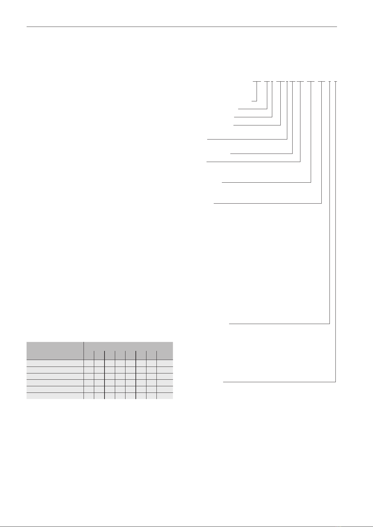
1.4.1 Model designation
Example:
150-270/0304SPXC-PM-W2-V-S
Nominal diameter of
pressure ange DN [mm]
Design dimensions
Hydraulic version
Motor rating [kW]
E.g.: 030 = 3.0 kW
Speed
4 = 1500 (60 Hz: 1800) min
-1
Impeller version
Model
X = standard
XC = Cooling jacket version
Motor model
= standard
PM = Permanent magnet motor
Materials
W0 = mixed materials
W1 = all castings manufactured from
EN-GJL-250
W2 = all castings apart from the impeller
manufactured from EN-GJL-250, impeller
manufactured from CuAl10Fe5Ni5-C
W3 = all castings apart from the impeller
manufactured from CuSn10-C, impeller
manufactured from CuAl10Fe5Ni5-C
W4 = all castings manufactured from 1.4408
W5 = all castings manufactured from
EN-GJS-400-15
W6 = all castings manufactured from 1.4439
W9 = Impeller manufactured from
CuAl10Fe5Ni5-C, intermediate casing
manufactured from CuSn10-C, pump
casing manufactured from EN-GJL-250
with epoxy resin hot powder coating
Flange position
V = front
VL = centred between the front and left
L = left
HL = centred between the rear and left
H = rear
HR = centred between the rear and right
R = right
VR = centred between the front and right
Construction
= standard
S = special construction
1)
Only exists in case of design with screw propeller.
2)
Only exists in case of design with closed multi vane impeller in material design W3, but not for 200-250/... and 200-270/...
3)
Only exists for filter strainer without sealing lip.
General information
9
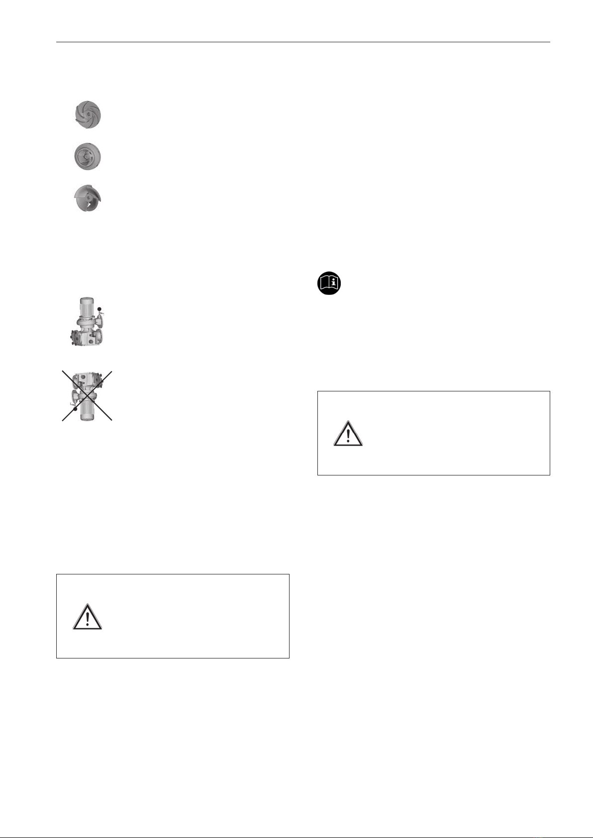
1.4.2 Impellers
Open and closed multi vane impellers and
screw propellers (SP) for clean to slightly
soiled pumped media are used.
Large contaminant particles are removed by
the integrated hair and fibre filter.
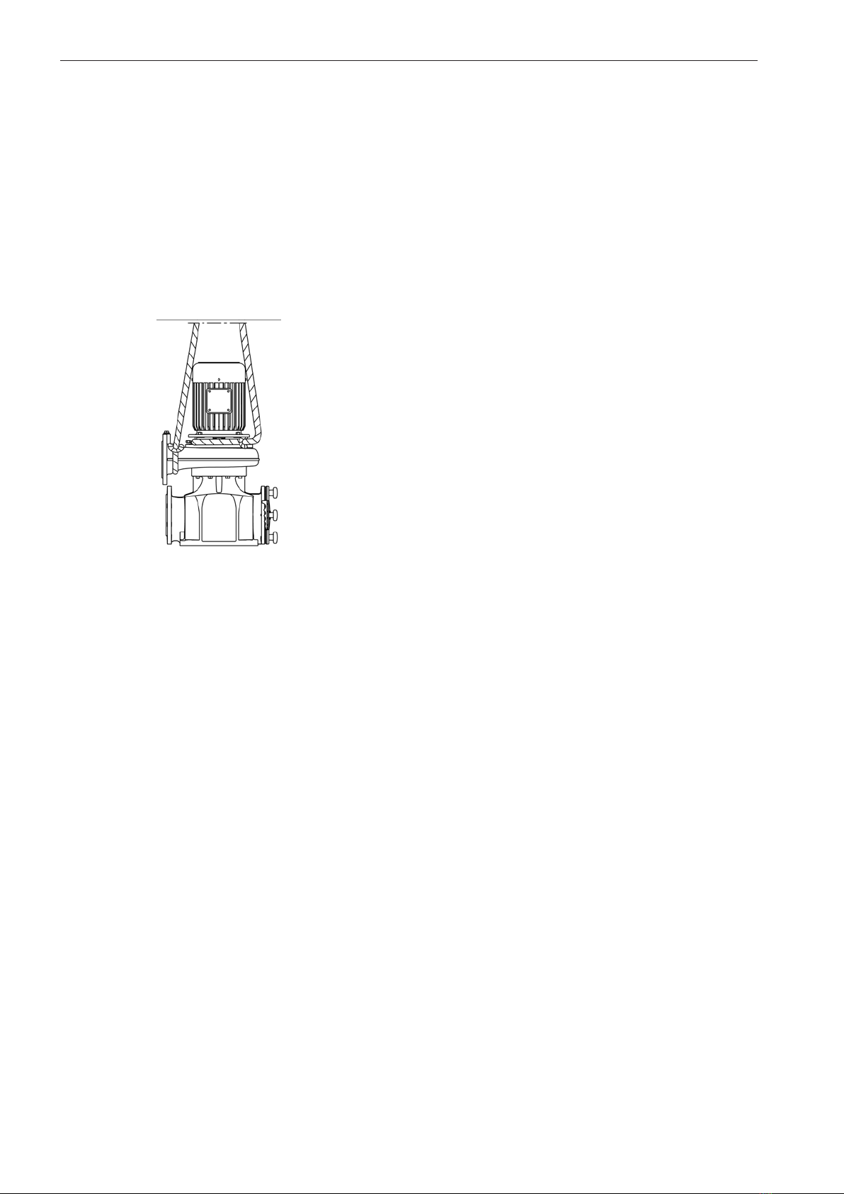
1.4.3 Installation
The pumps are delivered in vertical installation:
Vertical installation of the pump
It is not permitted to install the pump with the
"motor facing downwards" for operational
safety reasons.
1.4.4 Shaft sealing
The shaft sealing on the pump side is effected in all models
via a maintenance-free mechanical seal, which is independ-
ent of the direction of rotation and made from wear-resistant
silicon carbide (SiC).
All motors are equipped with a special seal for splash-proof-
ing on the pump side.
Caution!
Dry running the pump will destroy the
mechanical seal!
Ensure there is adequate cooling and
lubrication for the sliding surfaces.
An existing ETS X4 permits monitoring of the mechanical
seal to protect it from dry running.
1.4.5 Drive
A three-phase motor with squirrel-cage drives the pump. The
motor is cooled by the dissipation of heat from the cooling
fins to the ambient air.
The motor in UNIBAD-XC pumps is also equipped with a
jacket. The pumped medium cools this and absorbs the
motor heat.
In the case of pumps of the type UNIBAD-PM, a synchronous
motor with permanent excitation for operating the frequency
converter drives the pump. Observe the operating instruc-
tions included in delivery!
Important!
Observe the limit temperatures specified in section 1.4.7
'General data'.
The exact motor data can be found on the name plate.
Caution!
Incorrect warming will damage the
three-phase motor.
Maintain the voltage tolerance of ±
10 % according to DIN EN 60034-1.
Motor data for model X/XC
Design IM B5
Motor connection Manufacturer-specific
Protection type IP 55
Speed 1500 (1800) min
-1
Frequency 50 (60) Hz
Connection ≤ 2.2 kW 230 5/ 400 3(460 3) V
Connection ≥ 3.0 kW 400 5/ 690 3(460 5) V
Insulation class VDE 0530 F
General information
10
Ambient temperature range for:
lower limit temperature: - 5 °C
upper limit temperature: + 40 °C
Density and viscosity of the pumped medium:
Density: max. 1000 kg/m3
Kinematic viscosity: max. 1 mm2/s (1 cST)
Customised solutions may differ from this standard data.
Power correction:
Reduce the power according to the specifications of the mo-
tor manufacturer if motors are used at ambient temperatures
> 40 °C or at altitudes > 1000 m above sea level.
A differing density or viscosity alters the hydraulic perform-
ance of the pump. Observe the motor performance with
these media.
Sound pressure level:
The sound pressure level dB(A) of the pump during cavita-
tion-free operation lies within the range of Qoptimal below the
limit values specified in EC Machinery Directive 2006/42/
EC.
Model X
50/60 Hz
P2 [kW] 1500/1800 min
-1
1.1/1.3 55/59
1.5/1.8 55/59
2.2/2.6 59/63
3.0/3.6 59/63
4.0/4.8 59/63
5.5/6.6 63/67
7.5/9.0 63/67
11.0/13.2 65/69
15.0/18.0 65/69
18.5/22.2 65/69
22.0/26.4 67/71
30.0/36.0 68/72
37.0/44.4 70/74
45.0/54.0 70/74
55.0/66.0 71/75
Motor data for model X-PM
Design IM B5
Motor connection Manufacturer-specific
Protection type IP 55
Speed 1500 min
-1
Connection 3 300 - 400 V
Insulation class VDE 0530 F
Customised solutions may differ from this standard data.
1.4.6 Dimensions, weight, performance data
The measurements, installation dimensions and weight de-
tails can be found in section 5.2 'Dimensions'. The instruction
documents and the name plate data specify the performance
and connection data of the respective pump type.
The performance verification of the pumps is performed ac-
cording to DIN EN ISO 9906 (Rotodynamic pumps - Hydraulic
performance acceptance tests), Class 2.
1.4.7 General data
Media temperature range for:
lower limit temperature: - 5 °C
upper limit temperature: + 60 °C
Caution!
In type UNIBAD-XC pumps, pumped
media < 15°C and > 40°C damage
the motor.
Connect another cooling circuit to the
motor.

General information
11
Model XC
50/60 Hz
P2 [kW] 1500/1800 min
-1
1.5/1.8 49/53
2.2/2.6 49/53
3.0/3.6 49/53
4.0/4.8 49/53
5.5/6.6 49/53
7.5/9.0 49/53
11.0/13.2 50/54
15.0/18.0 50/54
18.5/22.2 52/56
22.0/26.4 52/56
30.0/36.0 52/56
Model X-PM
P2 [kW] 1500 min
-1
1.1 52
1.5 55
2.2 55
3.0 55
4.0 56
5.5 61
7.5 63
11.0 63
15.0 65
18.5 65
22.0 67
30.0 67
37.0 70
45.0 70
55.0 71
Safety
12
The following signal words represent
Danger!
This indicates an imminent danger. If it is
not avoided it will result in death or the most
severe of injuries.
Warning!
This indicates a potentially dangerous situa-
tion. If it is not avoided it can result in death
or the most severe of injuries.
Caution!
This indicates a potentially dangerous situa-
tion. If it is not avoided it can result in slight
or minor injuries or damage to property.
Notice!
This indicates a potentially hazardous situa-
tion. If it is not avoided the product or items
in its vicinity may be damaged.
Important!
This indicates application tips and other
particularly useful information. It is not a
signal word for a dangerous or hazardous
situation.
2.1.1 Machine identification
The information contained in this operating manual is only
applicable to the pump that is indicated on the title page.
Stick the supplied name plate of the pump into the operating
manual or on the control panel. This will ensure the relevant
data is available at any time.
2 Safety
2.1 Notes / explanations
The following symbols represent
Warning of a hazardous area
Warning of hand injuries
Warning of dangerous electrical voltage
Warning of explosive atmospheres
Warning of a biohazard
Warning of hot surfaces
Prohibited for people with pacemakers
Command to wear protective gloves
Command to refer to the operating instruc-
tions
General information
Safety
13
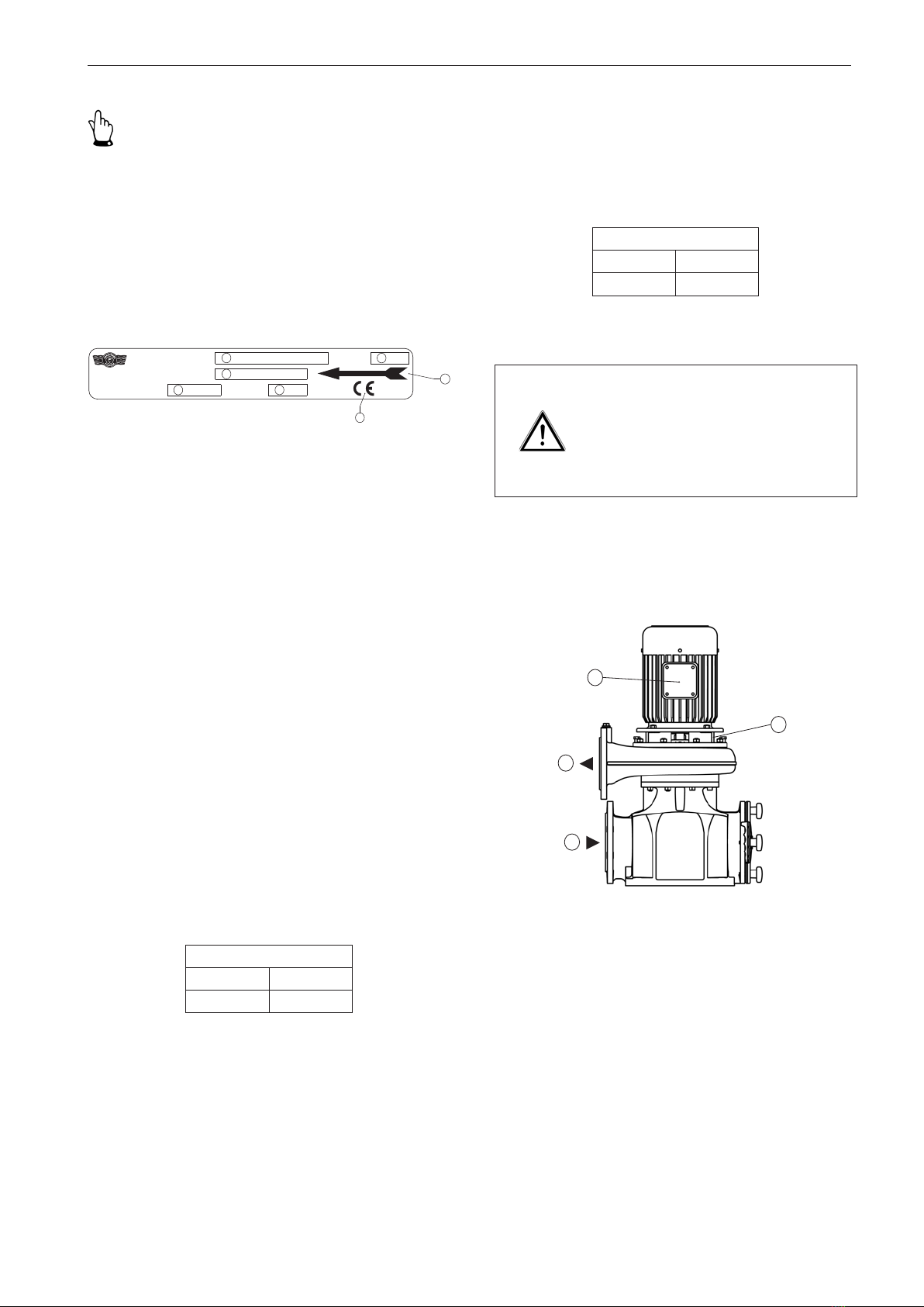
Figure 2 Name plate
Key to figure 2
1. Model designation
2. Year of manufacture/ month
3. Order No.
4. Nominal flow rate [m3/h]
5. Nominal head [m]
6. CE symbol
7. Observe the direction of rotation!
2.2 Integrated safety systems (optional)
Check the integrated safety devices in regular inspection
intervals j= annually.
The inspection methods applied here are:
S= Visual inspection, F= Functional check.
Winding protection
If the pump is also equipped with thermal winding protec-
tion with direct temperature monitoring, this switches off the
pump's motor if it starts to get too hot.
Inspection
Interval Method
j S, F
Important!
When making any inquiries and ordering spare parts
please make sure you specify the pump type and the order
number.
Also observe the name plate on the motor.
The name plate is attached to the fan hood or the motor
housing (UNIBAD-XC).
ETS X4
An existing ETS X4 (electronic dry running protection system)
that uses a vibrating fork sensor prevents the dry running
of the slide ring seal. This protects the functionability of the
pump.
Inspection
Interval Method
j S, F
Caution!
Incorrect warming will damage the
three-phase motor.
Do not decommission safety equipment
or change its mode of operation.
2.3 Connections on the pump
Figure 3 Connections on the pump
The following connections are available on the pump:
1. Inlet connecting flange
2. Outlet connecting flange
3. Electric connection (terminal box)
4. Venting
1.
2.
3.
4.
Auftrag-Nr.
Q
Bj./ Mon.
m
m/h
3
1
3
45
2
6
UNIBAD
Pumpe
Herborner Pumpenfabrik
J.H. Hoffmann GmbH&Co. KG
Littau3-5, DE-35745 Herborn
7

Safety
14
2.4 Safety measures
This operating manual is part of the machine and, as such,
must always be made available to operating personnel.
Please make sure that
- you observe the safety precautions it contains,
- you retain this operating manual for future use,
- you adhere to the frequency of inspections and control
measures.
The work described in this operating manual is specified in
such a way that enables
- a trained person to understand and im-
plement instructions associated with the
section 'Commissioning',
- a specialist to understand and implement
instructions associated with the sections
'Transport', 'Installation / fitting', 'Mainte-
nance / cleaning' and 'Disturbance / cause
/ trouble shooting'.
Important!
A trained person is understood to be a person who
- has been instructed by a specialist about the tasks they
are assigned and the possible dangers associated with
improper conduct,
- has received practical training, if necessary, and
- has been informed about the necessary protective equip-
ment and precautions.
Important!
According to EN 60204-1 a person is understood to be a
specialist if they
- are able to use their professional training, knowledge and
experience as well as knowledge of the relevant standards
to assess the work they have been assigned and
- are also able to identify any potential dangers.
2.5 Obligations of the operator
The operator is obligated to:
- instruct his/her operating and maintenance personnel with
regard to the pump's safety equipment and
- monitor compliance with the safety measures.
Important!
In the European Economic Area observe and comply with
- the national realisation of the framework directive (89/391/
EEC) with regard to the implementation of measures for
improving the protection of health and safety of workers
at work,
- as well as the associated specific directives and the direc-
tive (89/655/EEC), in particular, concerning the minimum
requirements for the protection of health and safety of
workers when using equipment at work and
- the occupational safety regulations.
The operator has to obtain the local operating licences and
observe the associated conditions.
In addition he/she also has to comply with the local statutory
provisions for
- the safety of personnel (accident preven-
tion regulations)
- the safety of operating equipment (protec-
tive equipment and maintenance)
- product disposal (waste management
law)
- material disposal (waste management
law)
- cleaning (cleaning agents and their dis-
posal)
- and the relevant environmental con-
straints.
Connections:
Observe the local regulations (e.g. for electrical connection)
for fitting, installation and commissioning.
General hazard warnings
15
3 General hazard warnings
3.1 Dangers
Warning!
Maintenance and repair work can
cause hand injuries.
Observe all of the safety precautions.
Observe the safety systems and safety precautions that are
described in this manual. The pump is operated by the control
elements or by the superordinate system. Keep the access
area free from any clutter while operating the pump in order
to ensure unrestricted access at all times.
3.2 Danger zones on the pump
A radius of approximately 1 m around the pump is designated
a danger zone for maintenance and cleaning work. The
control elements form the only operating area.
Caution!
Material escaping from the pump can
cause injuries.
Install or secure the pump in such
a way that the direction of pumping
is away from areas personnel may
frequent.
3.3 Assembly, operation and maintenance person-
nel
Assembly, operation and maintenance personnel are re-
sponsible for the transportation, fitting, installation, operation,
cleaning and reparation of the pump.
1. Only trained and authorised persons may
install and operate the pump.
2. Clearly define and observe the respon-
sibilities for operating the pump.
3. Observe the shut off procedures speci-
fied in the operating manual for all work
processes (operation, maintenance,
repair, etc.).
4. The operator should not impair the safety
of the pump.
5. The operator has to ensure that only au-
thorised persons work with the pump.
6. The user must notify the operator im-
mediately of any alterations to the pump
which affect the safety measures.
7. The operator may only actuate the pump
if it is in a perfect condition.
8. The operator has to provide the operat-
ing staff with the appropriate protective
equipment according to the statutory
requirements and the pumped medium.
3.4 Installation of replacement parts and wear parts
Replacement parts and accessories that are not supplied
by the manufacturer are unchecked and, as such, are not
approved. The installation and/or use of such products may
adversely affect the specified properties of your pump.
The manufacturer accepts no responsibility whatsoever for
any damage caused by the use of non-original parts and
accessories.

General hazard warnings
16
3.5 Shut off procedures
The following shut off procedure must be complied with
before conducting any maintenance, cleaning and/or repair
work (only by specialists).
Warning!
Electric current can result in death.
Disconnect the block motor (802) ac-
cording to the 5 safety rules.
When cleaning close any electrical
cabinets that are open to prevent dust
or water from entering.
The five safety rules are as follows:
1.Disconnect.
2.Secure against reactivation.
3.De-energise.
4.Earth and short-circuit.
5.Cover or shield any adjacent live parts.
Transport
17
Packaging for transportation by HGV
When the pump is transported by HGV it is packed and
secured on a transport pallet.
4.2.2 Intermediate storage
The freight packaging of the pump and the spare parts
are suitable for storage for a period of approximately 3
months.
Storage conditions
An enclosed and dry room with an ambient temperature of
5 - 40 °C.
4.3 Transport to the site of installation (by the cus-
tomer)
The pump should only be transported on a transport pallet by
specialist personnel in accordance with local conditions.
Warning!
An improperly secured pump can
cause severe injuries.
Make sure that lifting devices and stop
belts are adequate for the total weight
of the pump (see section 5.2 'Dimen-
sions').
If necessary, secure the pump during
transport using separate lifting acces-
sories.
Only set up the pump on a sufficiently
solid surface that is level in all direc-
tions.
4.3.1 Transport with a forklift truck
- The forklift must be designed to support
the weight of the pump.
- The driver must be authorised to operate
the forklift truck.
4 Transport
4.1 Scope of delivery
The detailed scope of delivery can be viewed in the order
confirmation.
4.2 Transport and packaging
The pumps are carefully checked and packed before being
shipped. However, damage developing during transport
cannot be excluded.
4.2.1 Delivery (including spare parts and replacement
parts)
Receiving inspection
Check the completeness of the order based on the delivery
note!
Damage
Check the delivery for signs of damage (visual inspection)!
Complaints
If the delivery has been damaged during transport:
- Contact the last shipping agent immedi-
ately!
- Keep the packaging (for possible review
by the shipping agent or for return ship-
ment)
Packaging for return shipment
If possible, use the original packaging and the original
packaging material.
If neither is available:
- Contact a packaging company with spe-
cialist staff if necessary.
Place the pump on a pallet (which must
be capable of supporting the weight).
- Please contact the manufacturer if you
have any queries with regard to packaging
and transport security.
Transport
18
Figure 4 Transport with a crane
The measurements, installation dimensions and weight
details can be found in section 5.2 'Dimensions'.
4.3.2 Transport with a crane
- The crane must be able to support the full
weight of the pump.
- The operator must be authorised to oper-
ate the crane.
- Attach the pump to the crane using the
corresponding separate lifting accessories
(e.g. cross bar, stop belt, ropes, etc.) and
the respective attachment points.
Installation / fitting
19
5 Installation / fitting
5.1 Installation
Prepare the construction in accordance with the pump
dimensions.
Important!
Provide sufficient room for maintenance and repair proce-
dures!
Plan for sufficient room for opening the terminal box, for
the electrical connection, and for any existing frequency
converters.
The concrete foundation must
- have hardened,
- exhibit satisfactory rigidity (at least class
X0 according to DIN EN 206),
- have a horizontal and flat surface,
- be able to absorb vibrations, effects of
force and impacts and
- be dimensioned in such a way that the star
handles (004) on the filter cover (003) can
be turned by hand.
Only then should the pump be installed.
The connection flanges must be perfectly aligned and
screwed in such a way that prevents leakage. The seals
must be resistant to the pumped medium.
Caution!
Incorrect warming will damage the
three-phase motor.
Ensure there is an adequate supply of
cooling air during operation (except for
UNIBAD-XC models).
In order to prevent transferring vibrations to the building
and the pipeline system it is recommended to install pipe
compensators and vibration dampers.
Caution!
Injuries may be caused when installing
the pump.
Observe the safety regulations and
the generally recognised "codes of
practice".
Installation / fitting
20
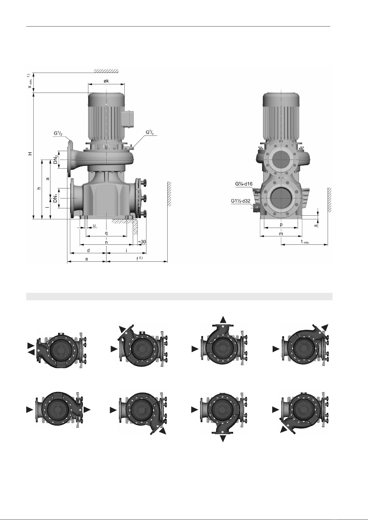
Flange position
3)
5.2 Dimensions
5.2.1 Dimensions of X/X-PM model
1.) When dismounting the motor ensure there is sufficient room for
the lifting device.
2.) Main controlling dimensions of filter strainer
Figure 5a Dimensions (X/X-PM model)
Figure V Figure L
Figure VR
Figure VL Figure HL
Figure H Figure HR Figure R
3.) The terminal box alignment may vary in the case of the design
with frequency converter.
Flange connection dimensions according to DIN 2501 PN 10
Dimensions with integrated frequency converter on request.
This manual suits for next models
2
Table of contents
Other HERBORNER pumpentechnik Water Pump manuals


Popular Water Pump manuals by other brands

GORMAN-RUPP PUMPS
GORMAN-RUPP PUMPS SE2D3 Installation, operation and maintenance manual

GORMAN-RUPP
GORMAN-RUPP SM SERIES manual

Graco
Graco ChemSafe 307 Instructions - parts

Macnaught
Macnaught OKT583-1-001 instruction manual

Graco
Graco SaniForce Operation

Ribimex
Ribimex PRPVC1100CI/1 User and maintenance manual

WITA
WITA Delta Plus UE 70A-XX PWM TRANSLATION OF THE ORIGINAL INSTALLATION AND OPERATING INSTRUCTIONS

Makita
Makita DVP181ZK instruction manual

Sicce
Sicce Voyager 2 instruction manual

Grundfos
Grundfos ALPHA 26-99 Installation and operating instructions

SKF
SKF Lincoln OCL-M-G Series Assembly instructions

Jilong
Jilong JL29P423NG manual


