herdstar MicroZone MPS100 Guide

Installation Manual
10/31/2014
0-10V Automatic Lamp & Mat Heating Control
Installation & Operation

Installation Manual
2
1400 Madison Ave, Suite 504 Mankato, MN 56001
PH: 507-344-8005 FAX: 507-344-8009
www.herdstar.com
Table of Contents
Installation Overview....................................................................................................................3
Mounting and Wiring....................................................................................................................3
Conduit and Connections.............................................................................................................3
Module Installation.......................................................................................................................4
Wiring/Setup ................................................................................................................................4
Wiring Multiple MPM100 Power Modulators into a System..........................................................4
Wiring MPM100 Power Modulator ...............................................................................................6
Wiring Instructions .......................................................................................................................7
Specifications...............................................................................................................................8
Service.........................................................................................................................................9
MicroZone is a trademark of HerdStar LLC.
Copyright © 2014 HerdStar LLC. All rights reserved.
Printed in the USA

Installation Manual
3
Installation Overview
This section covers the mounting and wiring of the MicroZone system. Anyone responsible for
programming and operating the MicroZone should also read the MicroZone Operations Manual.
There are two symbols commonly used throughout this section:
This symbol means the text describes steps that involve going near terminals with
potentially deadly voltage. Always shut off power to all MicroZone modules and all
attached devices before opening the cover.
This symbol means the text has extra importance since it is describing the importance
of a feature or explaining a step to which you should pay close attention to avoid
problems.
Mounting and Wiring
Mount the MicroZone MC110A control module indoors where the temperature remains between 0
degrees Fahrenheit (- 17 degree Celsius) and 105 degrees Fahrenheit (40 degrees Celsius).
Place the controller away from motors and relays/contactors that switch high current.
Do not install it in the same room where the animals live since the air tends to be corrosive to
electronic circuits. A separate room or control office is a preferred location.
Use the mounting holes on the enclosures for mounting the modules. Before you drill holes into
the enclosure, mark their locations and make sure that you do not drill into circuit boards and
cables.
Unless absolutely necessary, do not remove the circuit boards. They are static-sensitive
and should always be handled with appropriate grounding and electrostatic precautions.
Always remove power from the MicroZone modules and controlled devices before
removing any MicroZone module covers or servicing any heating device.
Conduit and Connections
To avoid electrical shorts or damage due to moisture, you should
never run conduit openings through the top of the box. Conduit
and hubs should be corrosion-resistant plastic or fiberglass. Use
only liquid-tight strain-relief connectors to bring wires into the
box.

Installation Manual
4
Module Installation
For trouble-free operation, follow these simple installation guidelines:
Electrical wiring used to connect the MicroZone modules must meet all state and local
regulatory requirements. Wire rated for 600 volts (minimum) is recommended.
Standard electrical conduit or raceways can be used to route wiring for the MicroZone
modules.
Do not install the modules in the same room where the animals live. A separate room or
hallway is a preferred location.
Do not install the modules where they will be subjected to harsh chemicals.
When fastening the covers to the units, be sure to only compress gaskets to ½ their original
size. This will result in a better seal to repel any moisture or dirt that may get into the units
and prevent normal operation.
Wiring/Setup
Below is a simplified diagram to show how the MicroZone units interconnect for a 120V
installation. A wiring diagram for 240V installation is on the next page. A qualified electrician can
easily wire the system with standard (600V-rated) wire.

Installation Manual
5
NOTE: To ensure proper operation of your MicroZone system, a dedicated Phase 2 wire must be run to the
Modulators (MPM100’s). This will prevent load current on the Phase 2 wire from interfering with proper
operation of the MPM100 modulator.
(For 120V operation, Phase 1 is the 120V hot line and Phase 2 is the neutral line.)

Installation Manual
6
Wiring Multiple MPM100 Power Modulators into a System
When wiring multiple MPM100 modules to a MC110A control unit, connect the orange and blue
control wires together in parallel, as shown in the diagram below. You can connect up to twelve
power modulators to a single MC110A control unit. Each power modulator will have its own
heating device circuit wiring.
Wiring MPM100 Power Modulator
Ensure power is removed from the power distribution panel before wiring in the heating
device feed circuit.
Ensure the power modulator (MPM100) and heating device supply circuits are properly grounded.
Always remove power from the MicroZone modules and controlled devices before
removing any MicroZone module covers.
Note that line voltages are still present when STANDBY is selected on units wired
for 240V operation.

Installation Manual
7
Wiring Instructions
MPS100 Power Supply
The power supply (MPS100) requires an input of 115 volts AC, 50/60 Hz. Using 14-16
gauge wires connect AC power to the BLACK (LINE), WHITE (NEUTRAL), and GREEN
(GROUND) power supply wires.
MC110A Control Unit
Matching wire color, connect the power supply RED +9VDC and BLACK -9VDC wires to
the MC110A control module’s RED and BLACK 9-12 VDC input wires.
Matching wire color, connect the MC110A control module’s ORANGE and BLUE control
wires to the MPM100 power module’s ORANGE and BLUE control wires. See the Wiring
Multiple MPM100 Power Modulators into a system section above for more information
MPM100 Power Modulator
Connect the MPM100’s (BLACK) wire to the power panel Phase 1.
Connect the MPM100’s (WHITE) wire to Phase 2 of the power panel with a dedicated wire.
Connect a wire from Phase 2 of the power panel to Line 2 of the heating devices.
Connect the MPM100’s LOAD (RED) wire to the L1 line of the heating devices.
NOTE: To ensure proper operation of your MicroZone system, a dedicated wire must be run
from the load center Phase 2 to the WHITE wire of the MPM100 modulators. This will prevent
lamp load current on Phase 2 from interfering with proper operation of the MPM100 modulator.
(For 120V operation, Phase 1 is the 120V hot line and Phase 2 is the neutral line.)

Installation Manual
8
System Setup / Operation
Initial System Configuration
New MicroZone installations require a one-time system configuration procedure before use. In this mode
you can change whether the unit is connected a heat lamp or a heat mat.
Changing System Configuration / Displaying Software Revision
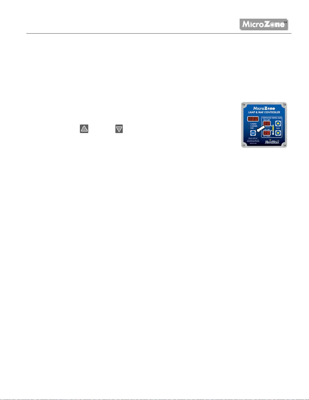
1. On the MC110A Controller, press and hold the SELECT key for
approximately 8 seconds (“H L” will be displayed above the SELECT key).
2. Press the UP or DOWN buttons to select between “HL” for heat lamps
and “HP” for heating pad (mats).
Troubleshooting
Common problems include incorrect wiring, tripped circuit breakers, burned out heat lamps or mats,
damaged power cords, etc. Internal diagnostics of the unit can detect other problems as follows:
Flashing “888” displayed –The MC110A needs to be returned to the factory for repair.
Flashing AUTO indicator –Communications between the Controller MC110A and the Modulator
have failed. The communications wiring may have been damaged or become disconnected.
Intermittent AUTO Indicator –The power modulator has detected a short circuit. When this
happens the power modulator will immediately turn off the output power, and after a 5 second
delay, slowly re-apply power. If the short circuit condition remains, the output power is turned off
and the cycle repeats until the condition is corrected. This feature protects the MicroZone modules
from a catastrophic failure. When infrared lamps are initially plugged in, or supply circuit
breaker turned on, the high surge current may cause this error code to be momentarily
displayed.
Resetting to Factory Default Settings
To restore your MicroZone to its factory default settings, turn off power to the MC110A controller. While
holding the SELECT key on the controller, reapply power to the system. The default settings will be
restored.

Installation Manual
9
Specifications
Operating Environment: 0° F to 105°, 10 to 95% RH (indoor use only)
MPS100 MicroZone Power Supply
Input Voltage: 120VAC, 0.1A, 50/60Hz
Output Supply: 200mA max output at 9 VDC
Output Capacity: Maximum of 5 MicroZone Controllers within 200 feet using 18AWG, two-
conductor wire.
MC110A MicroZone Controllers
Input Power: 9VDC
Temperature Specifications: +/- 2 degrees Fahrenheit at 30’
+/- 2.5 degrees Fahrenheit at 2000’ using 22AWG two-conductor cable
+/- 2.5 degrees Fahrenheit at 5000’ using 18AWG two-conductor cable
Communications Output Capacity: Maximum of 12 MPM MicroZone Power Modulators within 500
feet using 18AWG two-conductor wire.
MPM100 MicroZone Power Modulator
Input Power: 120/240VAC, 16A Maximum
Load Rating: 0-120VAC or 0-240VAC (2kW@120V or 4kw@240V Maximum)
Load Type: Resistive or Incandescent
Electrical protection: Short circuit, overload and voltage surge
Noise filter: FM radio filter
Enclosures: Weather tight (approximately 4” x 4” x 2”)
IMPORTANT:
Do not exceed the listed Load Rating and Operating Environment limits, or attempt to use the
MicroZone as an electronic speed control for electric motors.
Service
For assistance, make sure you have checked the parameters on the MicroZone. If you still need
assistance, contact:
1400 Madison Ave, Suite 504 Mankato, MN 56001
PH: 507-344-8005 FAX: 507-344-8009
www.herdstar.com
This manual suits for next models
2
Table of contents
Popular Lighting Equipment manuals by other brands

STERNO HOME
STERNO HOME GL33600 instructions

Welch Allyn
Welch Allyn LS200 Procedure Light owner's manual

Quasar Science
Quasar Science Rainbow 2 quick start guide

Photoflex
Photoflex LS2205 Assembling

Gama Sonic
Gama Sonic 20B50033 instruction manual

LUMENWERX
LUMENWERX RIM VERSO ACOUSTIX installation instructions