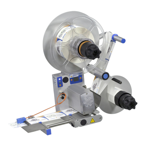
Herma 400 User manual

Translation of the original operating
instructions
HERMA 400
HERMA GmbH · Geschäftsbereich Maschinen · Plochinger Str. 48 · D-73779 Deizisau · Germany
EN
Hier und in
Kapitel 10
Geräteschild
aufkleben!

PREFACE Translation of the original operating instructions HERMA 400
2/130 3.26 EN (200416)
Preface
These operating instructions are to help you to safely set up your applicator and operate it troublefree.
You should read all of these instructions before starting the applicator in order to get well acquainted
with it.
If you have any queries or suggestions regarding your applicator or this manual please contact us.
Your questions, suggestions and comments are always welcome.
HERMA GmbH, Labelling Machines Division
www.herma.com
www.herma-components.com
Explanation of signs
DANGER
Indicates a hazardous situation which,if not avoided, will result in
death or serious injury.
WARNING
Indicates a hazardous situation which, if not avoided, may result
in death or serious injury.
CAUTION
Indicates a hazardous situation which,if not avoided, will result in
minor or moderate injury.
NOTICE
Indicates a situation which, if not avoided, will result in physical
damage at your applicator.
Indicates information you should take notice of.
Note
Except for internal use, including integration in the customer‘s documentation, no part of this
documentation may be reproduced or processed, copied, or distributed with the help of electronic
systems in any form without prior written permission of HERMA GmbH.
Version 3.26 EN (200416)
2016 © Copyright HERMA GmbH

Translation of the original operating instructions HERMA 400 CONVENTIONS
b
3.26 EN (200416) 3/130
Conventions
Switch-on key
Manual feed key
Function key
LED (on)
LED (blinks)
LED (off)
Minus key
Plus key
Enter key
Elements of the HERMA 400 control are designated and depicted in these instructions as follows:
Find further explanation on these elements in section 5.1.1.
Notes: A few of the illustrations used in this manual are examples and may differ sightly from the
configuration of your applicator.
Furthermore, note that the HERMA400 applicator is available in both left and right-hand
versions and that some illustrations may only show one of these versions.

CONVENTIONS Translation of the original operating instructions HERMA 400
4/130 3.26 EN (200416)
www.herma.com
www.herma-components.com

Translation of the original operating instructions HERMA 400 TABLE OF CONTENTS
3.26 EN (200416) 5/130
Table of Contents
1Safety11
1.1 Important Safety Precautions 11
1.2 General safety information 12
2 Transport, installation and connection 13
2.1 Transporting the applicator 13
2.2 Installing the machine 13
2.3 Electrical connection 14
2.3.1 Connections 15
3 Area of application 17
3.1 Intended use of the machine 17
3.2 Adhesive labels 17
4 Inserting the label web 19
4.1 Label web insertion schemes 19
4.1.1 Right-hand applicator with standard dispensing plate 19
4.1.2 Left-hand applicator with standard dispensing plate 19
4.1.3 Right-hand applicator with pivot beak 20
4.1.4 Left-hand applicator with pivot beak 20
4.1.4.1 Detailed illustrations 20
4.1.5 Right-hand applicator with dispensing plate with spring-loaded roller, 75° angular 21
4.1.6 Left-hand applicator with dispensing plate with spring-loaded roller, 75° angular 21
4.1.7 Winder system, left-hand applicator 22
4.1.8 Winder system, right-hand applicator 23
4.1.9 Winder system, loop-type unwinder 24
5 Commissioning and operation 25
5.1 Operation / Settings via the HERMA 400 control 26
5.1.1 Design 27
5.1.1.1 Key pad 27
5.1.1.2 Display 29
5.1.2 Function diagram 29
5.1.3 End of reel and diminishing reel (internal) 30
5.2 Overview display structure HERMA 400 31
5.3 The display’s Quick Menu 32
5.3.1 Format selection (Quick Menu parameter, optional) 32
5.3.2 Start delay applicator (Quick Menu parameter) 33
5.3.3 Stop delay label (Quick Menu parameter) 33
5.3.4 Speed of the applicator (Quick Menu parameter) 34
5.3.5 Speed of the product (Quick Menu parameter, optional) 34
5.4 Potentiometers 34
5.5 The display’s configuration menu 35
5.5.1 Calling up 35
5.5.2 Design 35

TABLE OF CONTENTS Translation of the original operating instructions HERMA 400
6/130 3.26 EN (200416)
5.5.3 Menu 100 Basic data 35
5.5.3.1 120 Master encoder Pulses / revolution 35
5.5.3.2 121 Master encoder Distance / revolution 36
5.5.3.3 122 Master encoder Start compensation 36
5.5.3.4 123 Master encoder Stop compensation 36
5.5.3.5 124 Master encoder Mini loop on/off 36
5.5.3.6 125 Master encoder Mini loop start delay 36
5.5.3.7 126 Master encoder Mini loop size 36
5.5.3.8 115 Master enc. transfer 36
5.5.3.9 116 Master enc. transfer Label pos. difference 37
5.5.3.10 140 Start signal 37
5.5.3.11 141 Start signal Mark field 1 37
5.5.3.12 142 Start signal Mark field 2 37
5.5.3.13 143 Start signal Mark field 3 37
5.5.3.14 144 Start inhibit Start inhibit distance 37
5.5.3.15 160 Multi labelling 37
5.5.3.16 161 Multi labelling Number of labels 38
5.5.3.17 180 Stop signal 38
5.5.3.18 181 Stop signal Mark field 1 38
5.5.3.19 182 Stop signal Mark field 2 38
5.5.3.20 183 Stop signal Mark field 3 38
5.5.3.21 184 Stop inhibit Stop inhibit distance 38
5.5.3.22 185 Hole inhibit Hole inhibit distance 38
5.5.3.23 187 Stop sensor Label position 39
5.5.3.24 188 Stop at missing label 39
5.5.3.25 189 Stop sensor: NoLabel 39
5.5.3.26 190 Printer on/off 39
5.5.3.27 192 Printer Every nth label 39
5.5.3.28 194 Printer Start delay 39
5.5.3.29 195 Printer Print time 39
5.5.3.30 195 Printer Printing length 40
5.5.4 Menu 200 Transfer data 41
5.5.4.1 201 Application type 41
5.5.4.2 210 Pivot beak on/off 42
5.5.4.3 211 Pivot beak Type 42
5.5.4.4 212 Pivot beak Start delay 42
5.5.4.5 213 Pivot beak Activation time 42
5.5.4.6 214 Pivot beak Stop delay 42
5.5.4.7 215 Roller unit start delay 43
5.5.4.8 216 Roller unit stop delay 43
5.5.4.9 225 Dispensing unit Label start delay 44
5.5.4.10 226 Dispensing unit Work pos. reached 44
5.5.4.11 227 Dispensing unit Work pos. return del. 44
5.5.4.12 229 Dispensing unit Home pos. reached 44
5.5.4.13 236 Transfer unit Work pos. reached 44
5.5.4.14 237 Transfer unit Work pos. return del. 44
5.5.4.15 238 Transfer unit Blow 44
5.5.4.16 239 Transfer unit Home pos. reached 44
5.5.4.17 239 Transfer unit After blow 44
5.5.4.18 260 Prism control system 45
5.5.4.19 261 Outfeed jam Running time 45
5.5.4.20 262 AUTOMATIC Slow-down time 45
5.5.4.21 263 Prism Start delay 45
5.5.4.22 264 Prism Stop delay 45
5.5.4.23 265 Start detection Start delay 45
5.5.4.24 266 Start detection Start monitoring 45
5.5.4.25 267 Auxiliary control system 46
5.5.4.26 268: Auxiliary Start delay 46
5.5.4.27 269: Auxiliary Stop delay 46

Translation of the original operating instructions HERMA 400 TABLE OF CONTENTS
3.26 EN (200416) 7/130
5.5.4.28 280 Label check on / off 47
5.5.4.29 284 Label check aft. feed 47
5.5.4.30 285 Lab. check aft. transf. 47
5.5.4.31 286 Label check start delay 47
5.5.5 Menu 400 Format 48
5.5.5.1 410 Format load 48
5.5.5.2 420 Format save 48
5.5.5.3 422 Format save Enter name 48
5.5.5.4 430 Format delete 48
5.5.6 Menu 500 Batch 49
5.5.6.1 510 Batch size 49
5.5.7 Menu 900 System 50
5.5.7.1 910 Rotate display drehen 50
5.5.7.2 912 Sprache / Language 50
5.5.7.3 915 Ready screen 50
5.5.7.4 940 Alarm message after missing labels 51
5.5.7.5 941 Alarm message after end of reel 51
5.5.7.6 942 Alarm message after undefined web move 51
5.5.7.7 943 Alarm message after start sequ. too close 51
5.5.7.8 947 Unwinder disc 51
5.5.7.9 948 Diminishing reel diameter 51
5.5.7.10 980 Bluetooth 51
5.5.7.11 990 Bus adress (RS485) 52
5.5.7.12 992 Display add. output 52
5.5.7.13 997 Serial no. applic. 52
5.5.7.14 950 Unwinder oper. modes 52
5.5.7.15 951 Unwinder output 53
5.5.7.16 952 Loop unwinder 54
5.5.7.17 953 Loop unwinder output 54
6 Overview and sub-assemblies 57
6.1 Overview 57
6.1.1 Function 57
6.2 Sub-assemblies 58
6.2.1 Standard unwinder 59
6.2.2 Motorized unwinder – Slim line version 63
6.2.3 Motorized loop-type unwinder – Slim line version 68
6.2.4 Label web brake 72
6.2.5 Label sensor FS03 74
6.2.5.1 Work mode (normal mode) 74
6.2.5.2 Setting mode 75
6.2.6 Label sensor optoelectronic 79
6.2.7 Dispensing sytems 81
6.2.7.1 Rigid/Straight dispensing plates 81
6.2.7.2 Dispensing plate, 15° angular 82
6.2.7.3 Pivot beak / Application unit 83
6.2.7.4 Moving beak 84
6.2.8 Transfer systems 85
6.2.8.1 Telescope 85
6.2.8.2 Transverse transfer system 86
6.2.9 Drive/Transport roller 89
6.2.10 Backing paper take-up unit standard 90
6.2.11 Motorized rewinder – Slim line version 95
7 Troubleshooting 103
7.1 Indication of malfunctions 103

TABLE OF CONTENTS Translation of the original operating instructions HERMA 400
8/130 3.26 EN (200416)
7.1.1 List of malfunctions (indicated via display) 104
7.1.1.1 SM106 Missing label at dispensing beak 104
7.1.1.2 SM107 End of label web 104
7.1.1.3 SM108 Dispensing unit does not reach home position 104
7.1.1.4 SM109 Dispensing unit does not leave home position 104
7.1.1.5 SM110 Dispensing unit does not reach work position 104
7.1.1.6 SM111 Dispensing unit does not leave work position 104
7.1.1.7 SM113 Transfer unit does not reach home position 104
7.1.1.8 SM114 Transfer unit does not leave home position 105
7.1.1.9 SM115 Transfer unit does not reach work position 105
7.1.1.10 SM116 Transfer unit does not leave work position 105
7.1.1.11 SM119 Label check Error after label feed 105
7.1.1.12 SM120 Label check Error after label transfer 105
7.1.1.13 SM134 Printer fault 105
7.1.1.14 SM141 Undefined movement of label web 105
7.1.1.15 SM148 Missing label series fault (web break?) 106
7.1.1.16 SM153 Multi labelling Start sequence too close 106
7.1.1.17 SM154 Batch finished! 106
7.1.1.18 SM162 Start delay too low or vMax was exceeded 106
7.1.1.19 SM163 Start sequence too close 106
7.1.1.20 SM164 Start signal Sensor mark not detected 106
7.1.1.21 SM165 Roller unit Communication error 106
7.1.1.22 SM166 Applicator Communication error 106
7.1.1.23 SM167 Roller unit Error 106
7.1.1.24 SM168 CAN connection Disconnect! 106
7.1.1.25 SM169 Firmware update required! 107
7.1.1.26 SM170 Bluetooth Initialization error! 107
7.1.1.27 SM171 Bluetooth H400 S/N required! 107
7.1.1.28 SM180 Printer not finished 107
7.1.1.29 SM181 Chip changed! 107
7.1.1.30 SM185 Firmware update Winder required 107
7.1.1.31 SM198 CAN communikation Response time 107
7.1.1.32 SM199 CAN communication no CAN module detected 107
7.1.1.33 SM805 Unwinder failure TEACH process 107
7.1.1.34 SM808 Unwinder failure Too slow 107
7.1.1.35 SM809 Unwinder failure Circuit voltage too low 107
7.1.1.36 SM810 Unwinder failure Overload 108
7.1.1.37 SM811 Unwinder failure Temperature too high 108
7.1.1.38 SM812 Unwinder failure End of reel 108
7.1.1.39 SM813 Unwinder failure Diameter determination 108
7.1.1.40 SM825 Loop unwinder failure TEACH process 108
7.1.1.41 SM828 Loop unwinder failure Too slow 108
7.1.1.42 SM829 Loop unwinder failure Circuit voltage too low 108
7.1.1.43 SM830 Loop unwinder failure Overload 108
7.1.1.44 SM831 Loop unwinder failure Temperature too high 108
7.1.1.45 SM832 Loop unwinder failure End of reel 108
7.1.1.46 SM845 Winder failure TEACH process 108
7.1.1.47 SM848 Winder failure Torn tape / too slow 108
7.1.1.48 SM849 Winder failure Circuit voltage too low 108
7.1.1.49 SM850 Winder failure Overload 109
7.1.1.50 SM851 Winder failure Temperature too high 109
7.1.1.51 SM865 Loop filler failure 109
7.1.1.52 SM910 Drive failure Low voltage 109
7.1.1.53 SM911 Drive failure High voltage 109
7.1.1.54 SM912 Drive failure High temperature 109
7.1.1.55 SM913 Drive failure Overload (period) 109
7.1.1.56 SM914 Drive failure 109
7.1.1.57 SM917 Drive failure Powerfail 109
7.1.1.58 SM918 Drive failure 109

Translation of the original operating instructions HERMA 400 TABLE OF CONTENTS
3.26 EN (200416) 9/130
7.1.1.59 SM919 Drive failure Low voltage (peak) 109
7.1.1.60 SM920 Drive failure Overload (peak) 109
7.1.1.61 SM921 Drive failure 110
7.1.1.62 SM922 Drive failure 110
7.1.1.63 SM923 Drive failure 110
7.1.1.64 SM924 Drive failure Overload 110
7.1.1.65 SM925 CAN communication disturbed 110
7.1.1.66 SM926 Drive failure: Overload (vMax exceeded!) 110
7.1.1.67 SM999 Drive mode was changed! f-button = restart 110
7.1.2 Malfunction table (LED indication) 111
7.1.2.1 Remedy of malfunctions 112
7.1.3 Error blink codes with PLC connection 112
7.2 Other malfunctions 113
7.3 Replace the drive unit 115
7.3.1 Remove the drive unit 115
7.3.2 Ship the drive unit 117
7.3.3 Mount the drive unit 117
7.4 Technical Service 117
8 Cleaning, maintenance, service 119
9 Technical Data 121
9.1 Inputs / outputs (X10) (option, standard signals) 123
9.2 Inputs / outputs (X19) (option, extended signals) 124
10 Declaration of Incorporation 125
11 Spare parts 127
A1 Index 129

TABLE OF CONTENTS Translation of the original operating instructions HERMA 400
10/130 3.26 EN (200416)
www.herma.com
www.herma-components.com

3.26 EN (200416) 11/130
1Safety
1.1 Important Safety Precautions
WARNING
❏The applicator may not be used in explosive atmospheres.
❏Mount the applicator appropriately upstream of the energy
input.
❏The applicator/machine must have a mains disconnection
device to cut off the mains supply in case of malfunction.
❏Switch off the mains supply before maintaining or cleaning
the machine. Reattach protective covers after this work is
complete.
❏The machine may only be operated, maintained and serviced
by trained personnel. Additional training must be provided.
❏Installation/removal may only be performed by trained
specialists when the applicator is disconnected from the
mains supply. Mount the applicator appropriately upstream
of the energy input and put the protective covers back on.
❏Switch off the mains supply before maintenance and cleaning
of the applicator. Mount the applicator appropriately
upstream of the energy input and put the protective covers
back on.
❏Do not put your hands into rotating parts during operation.
CAUTION
❏Remove the roll of labels when transporting the applicator.
❏During operation, there is a risk of being cut when the label
web is moving.
Warning symbols
Symbols used on the applicator:
Risk of being drawn in
Dangerous electrical voltage

1
SAFETY Translation of the original operating instructions HERMA 400
12/130 3.26 EN (200416)
1.2 General safety information
WARNING
❏Before commissioning, ensure that the protective equipment
is functioning properly.
❏Check that the protective equipment is functioning properly
every time before starting work on the applicator.
❏If any protective equipment is not functioning properly,
replace it or repair it immediately.
❏The technical condition of the protective equipment must be
inspected at regular intervals by a qualified person, at least
once annually.
❏If you cannot ensure safe operation of the machine, you must
immediately shut down the machine and secure it against
future use.
❏The machine may be operated by trained staff only.
Additional training must be provided.
❏Distribute the operating instructions for safe operation.
❏Only use the machine to process suitable products.
❏Do not bypass any safety switches.
❏Note the cleaning methods described in these instructions.
❏Only use original replacement parts and accessories.
❏The machine may not be modified.
❏Keep the operating instructions in a safe place.
❏The operating instructions must be included when reselling
the machine.
The user is solely responsible for injuries or damage caused by improper use that is not in accordance
with the instructions in this manual.
Personal protective equipment
WARNING
❏Make sure to tie up long hair (if required, wear a hair net) and
avoid wide clothing.

3.26 EN (200416) 13/130
2Transport, installation and connection
2.1 Transporting the applicator
When you transport the applicator/the machine using a forklift/pallet truck, note the following
requirements:
WARNING
❏The means of transport must be approved for the weight of
the machine.
❏Note the safety regulations for transporting and lifting heavy
loads.
❏Guide the forks between the machine feet or the palette.
Be aware of the machine’s centre of gravity.
❏The forks must extend so they are sticking out on the other
side of the machine or the palette.
CAUTION
❏Remove the roll of labels when transporting the applicator.
2.2 Installing the machine
WARNING
❏The applicator may not be used in explosive atmospheres.
❏Only use the machine in dry areas.
❏Mount the applicator appropriately upstream of the energy
input.
❏Installation/removal may only be performed by trained
specialists when the applicator is disconnected from the
mains supply. Mount the applicator appropriately upstream of
the energy input and put the protective covers back on.
If you should notice damage due to transport when you unpack the machine inform your HERMA sales
office immediately.

2
TRANSPORT, INSTALLATION AND CONNECTION Translation of the original operating instructions HERMA 400
14/130 3.26 EN (200416)
Mount the applicator using the two mounting holes for round rods (2), Ø 30 mm, hole spacing: 182 mm.
Secure the mounting system appropriately on the rods, e.g. using a locking screw (3), a washer (4) or
the optional fine-adjustment device (5).
2.3 Electrical connection
WARNING
❏HERMA 400 applicators may only be operated on TN mains
networks.
❏Only connect the applicator to AC voltage, and check whether
your mains voltage complies with the voltage specification on
the nameplate.
❏Only connect the applicator to a properly installed, earthed
power socket or connect it appropriately in the control cabinet
of the relevant machine.
❏The applicator/machine must have a mains disconnection
device to cut off the mains supply in case of malfunction.
❏Work on electrical components may only be performed by
authorised specialists and in observance of the relevant
safety regulations.
❏Disconnect the applicator from the mains before working on
the parts of the electrical equipment.
❏When you disconnect the HERMA 400 applicator from the
mains, wait at least five minutes before opening the housing
or touching the connector pins. RESIDUAL VOLTAGES!
❏Mount the applicator appropriately upstream of the energy
input.
2
3
4
5

2
Translation of the original operating instructions HERMA 400 TRANSPORT, INSTALLATION AND CONNECTION
3.26 EN (200416) 15/130
2.3.1 Connections
The following connections are available at theHERMA 400 applicator (depending on the configuration):
X14 – Serial OUT
X16 – Labelling start
X19 – Inputs/Outputs (ext. signals)
X10 – Inputs/Outputs (stand. signals) /
signal column (optional)
X12 – Power supply
* X16 as special case, if X10/X19 occupied and separate start signal required .
Impossible with .
** X16 as start signal, if X10/X19 are free.
†Must be interrupted before effecting a program update or if initialized for the very first
time.
†† In the standard configuration as of applicator no. 206... pin 5 of the cable from X17 to X3
of the CAN-I/O board is plugged in (a). Furthermore a jumper from pin 7 to pin 8 is set on
X27 (b). Thus the signal „printer running“ / „printer error“ can be interrogated.
With motorized unwinders the signals for end of reel and diminishing reel can be detected at the same
time only if the unwinder is connected via CAN bus (X18). Detection of these web signals is effected
automatically.
If, however, external sensors for detecting end of reel (at X3) and diminishing reel (at X2) are to be
used at the same time for a motorized unwinder of the winder system at the CAN bus this plug of X17
must be removed from X3. The printer signal can then not be interrogated any longer.
Additionally the jumper from pin 7 to pin 8 on X27 must be removed since otherwise end of reel would
be indicated as a printer error.
X14 ()
/(X16 (special)*)
X16 (,,)/
X19 (,,,)**
X10 (,,,)
X12
X13 (all types)†
X11 (,,)
X18 (all types)†
Shownhere:left-handversion;
right-hand version is mirror-
inverted.
X13 – Serial IN
X11 – Master encoder
X18 – CAN extension
X17 – Transfer /
Printer ††
X15 – Label sensor
X17
X15
a
b

NOTICE
❏For the appropriate pin assignment of the connections, please
refer to the section 9or the separate wiring diagram 823299.
❏All plugs are secured with coupling rings. Do not tilt the
coupling rings when screwing it onto the socket because this
could damage the thread or render it unusable. Screw the
plugs in completely in order to ensure safe long-term contact.
2
TRANSPORT, INSTALLATION AND CONNECTION Translation of the original operating instructions HERMA 400
16/130 3.26 EN (200416)
See chapter 9 for the assignment of connectors X10 and X19 (if available).

3.26 EN (200416) 17/130
3Area of application
3.1 Intended use of the machine
WARNING
❏Any use other than the purpose described above, in
particularly using the system to wind any materials other
than rolls of labels, is considered unintended use and is
prohibited.
The HERMA 400 applicator is an electronically-controlled device that is to be used to apply different
adhesive labels to a wide variety of products.
You can use the applicator to unwind label rolls, dispense labels from the backing paper and then roll
up the backing material.
The applicator can be equipped with a printing unit if required. This allows the user to print labels with,
for example, lines of text, changing dates, bar codes and batch numbers.
3.2 Adhesive labels
Winding outside
1Label roll
2Label roll core
3Label
4Backing paper
3+4 Label web
Winding inside
1
2
3
4
1
2
3
4

3
AREA OF APPLICATION Translation of the original operating instructions HERMA 400
18/130 3.26 EN (200416)
www.herma.com
www.herma-components.com

3.26 EN (200416) 19/130
4Inserting the label web
4.1 Label web insertion schemes
The following schemes show how to insert the label web with the most common standard applicators.
A separate insertion scheme is provided for applicator configurations other than shown here . As the
case may be, this scheme may also be attached to the machine.
CAUTION
❏Before inserting the label web, ensure that the applicator/
machine is switched off.
4.1.1 Right-hand applicator with standard dispensing plate
4.1.2 Left-hand applicator with standard dispensing plate
OI
O = Außenwicklung / outside winding
I = Innenwicklung / inside winding
681297
681297
0 = Außenwicklung / outside winding
I = Innenwicklung / inside winding
O
I
O = Außenwicklung / outside winding
I = Innenwicklung / inside winding
681296
681296
0 = Außenwicklung / outside winding
I = Innenwicklung / inside winding

4
INSERTING THE LABEL WEB Translation of the original operating instructions HERMA 400
20/130 3.26 EN (200416)
4.1.3 Right-hand applicator with pivot beak
4.1.4 Left-hand applicator with pivot beak
4.1.4.1 Detailed illustrations
OI
O = Außenwicklung / outside winding
I = Innenwicklung / inside winding
681299
681299
0 = Außenwicklung / outside winding
I = Innenwicklung / inside winding
O
O = Außenwicklung / outside winding
I = Innenwicklung / inside winding
681298
I
681298
0 = Außenwicklung / outside winding
I = Innenwicklung / inside winding
Detail dispensing plate Detail pivot beak
Detail dispensing plate, 75° angular
Other manuals for 400
1
Table of contents
Other Herma Label Maker manuals
